EP0154227A1 - Système d'échange et procédé pour connecter et/ou échanger des éléments de manipulation à distance - Google Patents
Système d'échange et procédé pour connecter et/ou échanger des éléments de manipulation à distance Download PDFInfo
- Publication number
- EP0154227A1 EP0154227A1 EP19850101640 EP85101640A EP0154227A1 EP 0154227 A1 EP0154227 A1 EP 0154227A1 EP 19850101640 EP19850101640 EP 19850101640 EP 85101640 A EP85101640 A EP 85101640A EP 0154227 A1 EP0154227 A1 EP 0154227A1
- Authority
- EP
- European Patent Office
- Prior art keywords
- exchange unit
- exchange
- central control
- control source
- units
- Prior art date
- Legal status (The legal status is an assumption and is not a legal conclusion. Google has not performed a legal analysis and makes no representation as to the accuracy of the status listed.)
- Granted
Links
Images

Classifications
-
- B—PERFORMING OPERATIONS; TRANSPORTING
- B25—HAND TOOLS; PORTABLE POWER-DRIVEN TOOLS; MANIPULATORS
- B25J—MANIPULATORS; CHAMBERS PROVIDED WITH MANIPULATION DEVICES
- B25J15/00—Gripping heads and other end effectors
- B25J15/04—Gripping heads and other end effectors with provision for the remote detachment or exchange of the head or parts thereof
-
- B—PERFORMING OPERATIONS; TRANSPORTING
- B23—MACHINE TOOLS; METAL-WORKING NOT OTHERWISE PROVIDED FOR
- B23Q—DETAILS, COMPONENTS, OR ACCESSORIES FOR MACHINE TOOLS, e.g. ARRANGEMENTS FOR COPYING OR CONTROLLING; MACHINE TOOLS IN GENERAL CHARACTERISED BY THE CONSTRUCTION OF PARTICULAR DETAILS OR COMPONENTS; COMBINATIONS OR ASSOCIATIONS OF METAL-WORKING MACHINES, NOT DIRECTED TO A PARTICULAR RESULT
- B23Q1/00—Members which are comprised in the general build-up of a form of machine, particularly relatively large fixed members
- B23Q1/0063—Connecting non-slidable parts of machine tools to each other
-
- B—PERFORMING OPERATIONS; TRANSPORTING
- B23—MACHINE TOOLS; METAL-WORKING NOT OTHERWISE PROVIDED FOR
- B23Q—DETAILS, COMPONENTS, OR ACCESSORIES FOR MACHINE TOOLS, e.g. ARRANGEMENTS FOR COPYING OR CONTROLLING; MACHINE TOOLS IN GENERAL CHARACTERISED BY THE CONSTRUCTION OF PARTICULAR DETAILS OR COMPONENTS; COMBINATIONS OR ASSOCIATIONS OF METAL-WORKING MACHINES, NOT DIRECTED TO A PARTICULAR RESULT
- B23Q9/00—Arrangements for supporting or guiding portable metal-working machines or apparatus
- B23Q9/0064—Portable machines cooperating with guide means not supported by the workpiece during working
Definitions
- This invention relates to an exchange system and method for connecting a remote manipulable element to a central control source. More particularly, this invention is directed to an exchange unit and method capable of effecting automatic connection between a robot arm and a desired tool gripper selected from an array of tool grippers.
- Robot arms and tool grippers are well known in the art.
- prior art systems and methods suffer from the shortcoming that either the tool gripper is fixedly attached to the robot arm, as by screws, or that each tool gripper in a set, although connectable to and separable from the robot arm, requires its own separate umbilical connections for control distinct from that of the robot arm, with the result that there is a cumbersome and messy duplication of control input conduits.
- an exchange system for connecting a remote manipulable element to a central control source, characterized by a first exchange unit attachable to and in control signal communication with the central control source, the first exchange unit being provided with control signal conducting means; at least one second exchange unit matable with and releasably connectable to the first exchange unit and attachable to and in control signal communication with the remote manipulable element, the second exchange unit having control signal conducting means adapted for connection with the control signal conducting means in the first exchange unit on mating of said first and second exchange units; and locking means in signal communication with and responsive to the central control source for connecting and disconnecting the matable exchange units.
- the exchange system of this invention acts to connect a robot arm with any one of a plurality of tool grippers without the need for separate control input umbilicals to the gripper.
- the invention further provides the capability of automatically exchanging a selected tool gripper for any other gripper in a given array.
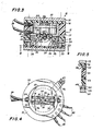
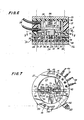
- the exploded view of the tool exchange system 10 shows its major components.
- An upper exchange unit 11 is attached to a robot arm 12 by means of an adapter plate 13.
- the adapter plate 13 is of the same diameter as the upper exchange unit 11 and has threaded holes 14 for attachment to upper exchange unit 11 by means of screws.
- Countersunk holes 15 are located on the adapter plate 13 as required for attachment of the adapter plate to a particular robot arm. As robot arms of various manufacturers have varying screw hole locations for tool attachment, holes 15 are varied for each different manufacture.
- Adapter plate 13 is preferably made of lightweight metal to provide for secure threading of the screw holes while minimizing weight.
- the body of upper exchange unit 11 includes a top plate 16, a cylindrical housing 17 and bottom plate 18. Mounts 19 for lifting fingers 20 are attached to and project downwardly from bottom plate 18.
- Upper exchange unit housing 17 is preferably formed of lightweight plastic and has receptacles for receiving input control signals, here depicted as a plurality of electrical wires 21 and pneumatic hoses 22 from a remote control source (not shown).
- the plastic body of housing 17 provides electrical insulation between the electrical connector elements 25. If desired, housing 17 could be formed of lightweight metal or other such noninsulative material. Such construction would require insulating sheaths around connector elements 25.
- upper exchange unit housing 17 has an annular recess 23 for passage of electrical control conduits 24 to desired locations about its circumference where they join vertical female connector elements 25 for passage to the face 26 of the housing.
- Pneumatic input control ports 27 intersect vertical bored conduits 28 in the wall of upper exchange unit housing 17 for communication with housing face 26. Additional inputs 29 communicate with the coupling drive unit 30.
- coupling drive unit 30 is a double acting pneumatic cylinder having a pneumatic input directed to each respective face of piston 31.
- a compression spring 56 may be mounted between the top of piston rod 57 and the lower face of plate 16 to provide fail-safe mating of the exchange units in the event of a loss of air pressure to pr.eumatic inputs 29.
- the initial force of the spring 56 should be selected to be great enough to hold piston 31 in its fully downward position without the maintenance of air pressure on pneumatic cylinder 30, while the compressed force should be not so great as to substantially inhibit retraction of piston 31 by air pressure delivered to cylinder 30 in normal operation.
- pneumatic inputs 20 may be provided with spring return blocking ports to maintain air pressure on cylinder 30 if the source of air.pressure fails.
- Output shaft 32 of pneumatic cylinder 30 passes through a hole in bottom plate 18 and has attached to it a yoke 33 by means of pivot pin 34. At each end of yoke 33 is mounted a lifting finger 20 by means of pivot pin 35. Lifting finger 20 is further connected to mount 19 by slide pin 36 which passes through elongated slot 37 in finger 20, so that a portion of the downward stroke of piston 31 and out- put shaft 32 is translated into lateral movement of hook 38 at the lower end of finger 20 during mating of upper exchange unit 11 with lower exchange unit 39.
- Upper exchange unit 11 also has bullet-nosed guide pins 40 projecting downwardly from its face 26 for general registry with alignment holes 41 in the face 42 of lower exchange unit 39 during mating.
- Guide pins 40 preferably extend farther from face 26 of upper exchange unit 11 than any other element to avoid damage to other elements of the upper or lower unit in the event of misalignment.
- Lower exchange unit 39 is preferably formed of the same materials as upper exchange unit 11 and has about the circumference of its upper face 42 spring-loaded male control connections 43 for mating with the corresponding female connections 25 on the face of upper exchange unit 11.
- Lower exchange unit 39 includes housing 51, adapter plate 52 for attaching the unit to a tool gripper 50, and bottom plate 53.
- lower exchange unit housing 51 is preferably formed of plastic and so provides electrical insulation between electrical connector elements 43. If housing 51 is formed of noninsulative material, connector elements 43 would require insulating sheaths.
- lower exchange unit 39 has an annular recess 44 corresponding to upper exchange unit recess 23 for passage of electrical control conduits 45 from male connectors 43 to output plug 46 for further connection through electrical wires 47 to the tool gripper 50.
- lower exchange unit 39 has bored conduits passing vertically through its wall to connect male pneumatic connectors 48 with pneumatic control output conduits 49 for passing pneumatic signals to tool gripper 50.
- Male connectors 48 preferably have an "0" ring seal, while female connectors 28 on upper exchange unit 11 are slightly chamfered, thus providing a secure, leak free pneumatic connection upon mating of the units..
- Male connectors rather than female are preferably located on the face 42 of lower exchange unit 39 to avoid collection of dust, dirt or other foreign matter which could readily occur on upwardly facing female connectors during storage.
- Alignment hole 41 is preferably on lower exchange unit 39 to facilitate visual alignment of that hole with guide pin 40 by an operator during initial set-up of the system, and may be bored completely through the lower exchange unit housing 51 and adapter plate 52 to avoid collection of foreign matter.
- Lower exchange unit 39 also has locking pins 54 mounted in its wall and extending radially inwardly. Locking pins 54 are located so as to align with hooks 38 at the outer ends of lifting fingers 20 during mating. These pins are preferably made of hardened steel or similar material.
- Bottom plate 53 of lower exchange unit 39 is preferably formed of lightweight metal and attaches to lower adapter plate 52.
- Lower adapter plate 52 is bored similarly to upper adapter plate 13 for attachment of lower exchange unit 39 to a tool gripper 50.
- the spring-loaded male electrical connectors 43 preferably extend upwardly about .06 to .08 inch beyond the upper face 42 of the lower exchange unit 39. Two of these connectors are preferably connected through their respective female connectors 25 to an input current and a ground and are wired in parallel to the terminals of coupling position indicator 55, which is preferably a low power LED display.
- each tool gripper 50 of an array of grippers has an associated lower exchange unit 39 connected to it by lower adapter plate 52 and control signal umbilicals 47 and 49.
- the tool grippers are preferably stored in an appropriate rack in a convenient orientation, usually vertically, for pick up by the robot arm 12 and associated upper exchange unit 11.
- an array of four tool grippers for performing four different operations would normally utilize four lower exchange units matable seriatim with one upper exchange unit.
- One upper exchange unit 11 is attached to the robot arm by adapter plate 13, and its associated control signal umbilicals 21 and 22 are connected to a remote signal source (not shown), which may or may not be an integral part of the robot arm 12.
- a remote signal source not shown
- an operator manipulates the robot arm 12 to locate the upper exchange unit 11 above the desired tool gripper and its associated lower exchange unit 39 stored in an appropriate rack, aligning bullet-nosed pins 40 with alignment holes 41. He then moves the upper exchange unit toward the lower exchange unit. As the units almost touch, the male electrical connectors 43 protruding beyond the upper face 42 of the lower exchange unit 39 contact their respective female connectors 25, thus energizing the coupling position indicator 55.
- a particulate tool gripper When a particulate tool gripper is to be released, it is positioned in an appropriate rack and a pneumatic signal is delivered against the lower face of drive piston 31 of cylinder 30, retracting output shaft 32 and so also retracting lifting fingers 20, Additionally, the lower surfaces of fingers 20 interfere slightly with bottom plate 53 of lower exchange unit 39 (Fig. 3) and this interference assists in urging the exchange units apart.
Landscapes
- Engineering & Computer Science (AREA)
- Mechanical Engineering (AREA)
- Robotics (AREA)
- Manipulator (AREA)
Applications Claiming Priority (2)
| Application Number | Priority Date | Filing Date | Title |
|---|---|---|---|
| US58808084A | 1984-03-09 | 1984-03-09 | |
| US588080 | 1984-03-09 |
Publications (2)
| Publication Number | Publication Date |
|---|---|
| EP0154227A1 true EP0154227A1 (fr) | 1985-09-11 |
| EP0154227B1 EP0154227B1 (fr) | 1989-11-02 |
Family
ID=24352402
Family Applications (1)
| Application Number | Title | Priority Date | Filing Date |
|---|---|---|---|
| EP19850101640 Expired EP0154227B1 (fr) | 1984-03-09 | 1985-02-14 | Système d'échange et procédé pour connecter et/ou échanger des éléments de manipulation à distance |
Country Status (4)
| Country | Link |
|---|---|
| EP (1) | EP0154227B1 (fr) |
| JP (1) | JPS60213494A (fr) |
| CA (1) | CA1251809A (fr) |
| DE (1) | DE3573995D1 (fr) |
Cited By (19)
| Publication number | Priority date | Publication date | Assignee | Title |
|---|---|---|---|---|
| WO1986002307A1 (fr) * | 1984-10-17 | 1986-04-24 | Plessey Overseas Limited | Dispositif de couplage debrayable pour robots |
| FR2591926A2 (fr) * | 1985-03-13 | 1987-06-26 | Dassault Avions | Dispositif pour l'accouplement d'une tete-outil au bras manipulateur d'un robot, et support pour le stockage de telles tetes-outils |
| EP0231411A1 (fr) * | 1982-09-29 | 1987-08-12 | The Boeing Company | Déconnecteur rapide pour outils reliés à un robot |
| WO1987004653A1 (fr) * | 1986-01-31 | 1987-08-13 | Robert Bosch Gmbh | Bras de robot avec bride de montage d'outils |
| FR2601614A1 (fr) * | 1986-07-16 | 1988-01-22 | Comau Spa | Dispositif de changement automatique d'outillage equipant des robots industriels. |
| GB2192855A (en) * | 1986-07-21 | 1988-01-27 | British Nuclear Fuels Plc | Tool-change coupling for robots |
| EP0466027A1 (fr) * | 1990-07-11 | 1992-01-15 | Kabushiki Kaisha Yaskawa Denki | Dispositif de changement d'outil pour robot |
| EP0361373A3 (fr) * | 1988-09-30 | 1992-09-09 | The Boeing Company | Système de changement d'outil de robot |
| US5664931A (en) * | 1995-08-02 | 1997-09-09 | R. A. Jones & Co., Inc. | Edge lifting end effector |
| WO1998034764A1 (fr) * | 1997-02-10 | 1998-08-13 | Asea Brown Boveri Ab | Dispositif comprenant un corps optique |
| EP0873826A3 (fr) * | 1997-04-23 | 1999-04-14 | COMAU S.p.A. | Poignet de robot |
| WO2009046761A1 (fr) * | 2007-10-09 | 2009-04-16 | Abb Technology Ab | Dispositif de robot industriel, robot industriel et procédé pour manipuler des objets |
| DE102014107642A1 (de) * | 2014-05-30 | 2015-12-03 | Deutsches Zentrum für Luft- und Raumfahrt e.V. | Adaptereinrichtung |
| CN109760080A (zh) * | 2018-12-27 | 2019-05-17 | 大族激光科技产业集团股份有限公司 | 一种机械夹具组及相关方法 |
| DE102018222735B3 (de) | 2018-12-21 | 2020-06-04 | Deutsches Zentrum für Luft- und Raumfahrt e.V. | Vorrichtung zur Kopplung eines Endeffektors mit einem Aktuator einer Maschine an einer Mensch-Maschine-Schnittstelle |
| CN111246981A (zh) * | 2017-10-30 | 2020-06-05 | 霓达株式会社 | 自动工具更换用联接器及自动工具更换装置 |
| DE102021133345A1 (de) | 2021-12-15 | 2023-06-15 | MATHEUS Industrie-Automation GmbH | Kompaktes Greiferwechselsystem für Industrieroboter |
| CN116323118A (zh) * | 2020-09-02 | 2023-06-23 | 马丁·齐默尔 | 层模块、适配器系统以及层模块系统 |
| EP4494819A1 (fr) * | 2023-07-20 | 2025-01-22 | J. Schmalz GmbH | Préhenseur magnétique, rangée de préhension, système de préhension et système de rangée de préhension |
Families Citing this family (12)
| Publication number | Priority date | Publication date | Assignee | Title |
|---|---|---|---|---|
| JPH078476B2 (ja) * | 1986-05-13 | 1995-02-01 | 本田技研工業株式会社 | ロボツト用ハンド交換装置 |
| JPH01289691A (ja) * | 1988-05-11 | 1989-11-21 | Nitta Ind Corp | 自動工具交換装置 |
| JPH0546866Y2 (fr) * | 1988-10-27 | 1993-12-08 | ||
| JPH0359185U (fr) * | 1989-10-16 | 1991-06-11 | ||
| JPH077104Y2 (ja) * | 1990-09-26 | 1995-02-22 | インダストリアル テクノロジー リサーチ インスチチュート | 工具自動交換装置用のロボットと工具の連結装置 |
| JP2566379B2 (ja) * | 1994-05-31 | 1996-12-25 | 宇宙開発事業団 | 結合装置 |
| KR101949057B1 (ko) * | 2014-08-20 | 2019-02-15 | 에이티아이 인더스트리얼 오토메이션, 인크. | 공구 스탠드 디커플링 전원을 갖는 로봇식 공구 교환기 |
| WO2019114893A1 (fr) * | 2017-12-14 | 2019-06-20 | Onrobot A/S | Dispositif de préhension |
| WO2020085388A1 (fr) * | 2018-10-25 | 2020-04-30 | ビー・エル・オートテック株式会社 | Module hydraulique |
| CN112789141B (zh) * | 2018-10-25 | 2025-02-14 | 必爱路自动化设备株式会社 | 流体模块 |
| JP7458864B2 (ja) * | 2020-04-06 | 2024-04-01 | 川崎重工業株式会社 | 絶縁ユニット、ロボット及び絶縁ユニットの取り付け方法 |
| CN115956219B (zh) | 2020-06-30 | 2025-05-09 | 特里瓦莱科技有限责任公司 | 液晶显示装置 |
Citations (6)
| Publication number | Priority date | Publication date | Assignee | Title |
|---|---|---|---|---|
| EP0036912A1 (fr) * | 1980-03-26 | 1981-10-07 | Maschinenfabrik Meyer AG. | Pince pour manipulateur |
| EP0088559A2 (fr) * | 1982-03-05 | 1983-09-14 | Fanuc Ltd. | Robot industriel pourvu d'un dispositif de support pour une main |
| EP0092967A2 (fr) * | 1982-04-27 | 1983-11-02 | Fanuc Ltd. | Dispositif de changement automatique du grappin pour les robots industriels |
| EP0120275A1 (fr) * | 1983-03-11 | 1984-10-03 | Syspro | Porte-outil pour robot industriel |
| DE3310192A1 (de) * | 1983-03-21 | 1984-10-04 | Mantec Gesellschaft für Automatisierungs- und Handhabungssysteme mbH, 8510 Fürth | Greiferkupplung fuer industrieroboter |
| DE3310070A1 (de) * | 1983-03-21 | 1984-10-04 | Mantec Gesellschaft für Automatisierungs- und Handhabungssysteme mbH, 8510 Fürth | Schnellkupplung fuer greifer von industrierobotern |
Family Cites Families (3)
| Publication number | Priority date | Publication date | Assignee | Title |
|---|---|---|---|---|
| JPS5317574Y2 (fr) * | 1972-03-31 | 1978-05-11 | ||
| JPS57170989U (fr) * | 1981-03-03 | 1982-10-27 | ||
| JPS58211874A (ja) * | 1982-06-02 | 1983-12-09 | 松下電器産業株式会社 | ロボツトハンドリングシステム |
-
1985
- 1985-02-14 DE DE8585101640T patent/DE3573995D1/de not_active Expired
- 1985-02-14 EP EP19850101640 patent/EP0154227B1/fr not_active Expired
- 1985-03-08 CA CA000476055A patent/CA1251809A/fr not_active Expired
- 1985-03-08 JP JP4498585A patent/JPS60213494A/ja active Granted
Patent Citations (6)
| Publication number | Priority date | Publication date | Assignee | Title |
|---|---|---|---|---|
| EP0036912A1 (fr) * | 1980-03-26 | 1981-10-07 | Maschinenfabrik Meyer AG. | Pince pour manipulateur |
| EP0088559A2 (fr) * | 1982-03-05 | 1983-09-14 | Fanuc Ltd. | Robot industriel pourvu d'un dispositif de support pour une main |
| EP0092967A2 (fr) * | 1982-04-27 | 1983-11-02 | Fanuc Ltd. | Dispositif de changement automatique du grappin pour les robots industriels |
| EP0120275A1 (fr) * | 1983-03-11 | 1984-10-03 | Syspro | Porte-outil pour robot industriel |
| DE3310192A1 (de) * | 1983-03-21 | 1984-10-04 | Mantec Gesellschaft für Automatisierungs- und Handhabungssysteme mbH, 8510 Fürth | Greiferkupplung fuer industrieroboter |
| DE3310070A1 (de) * | 1983-03-21 | 1984-10-04 | Mantec Gesellschaft für Automatisierungs- und Handhabungssysteme mbH, 8510 Fürth | Schnellkupplung fuer greifer von industrierobotern |
Cited By (21)
| Publication number | Priority date | Publication date | Assignee | Title |
|---|---|---|---|---|
| EP0231411A1 (fr) * | 1982-09-29 | 1987-08-12 | The Boeing Company | Déconnecteur rapide pour outils reliés à un robot |
| WO1986002307A1 (fr) * | 1984-10-17 | 1986-04-24 | Plessey Overseas Limited | Dispositif de couplage debrayable pour robots |
| FR2591926A2 (fr) * | 1985-03-13 | 1987-06-26 | Dassault Avions | Dispositif pour l'accouplement d'une tete-outil au bras manipulateur d'un robot, et support pour le stockage de telles tetes-outils |
| WO1987004653A1 (fr) * | 1986-01-31 | 1987-08-13 | Robert Bosch Gmbh | Bras de robot avec bride de montage d'outils |
| FR2601614A1 (fr) * | 1986-07-16 | 1988-01-22 | Comau Spa | Dispositif de changement automatique d'outillage equipant des robots industriels. |
| GB2192855A (en) * | 1986-07-21 | 1988-01-27 | British Nuclear Fuels Plc | Tool-change coupling for robots |
| EP0361373A3 (fr) * | 1988-09-30 | 1992-09-09 | The Boeing Company | Système de changement d'outil de robot |
| EP0466027A1 (fr) * | 1990-07-11 | 1992-01-15 | Kabushiki Kaisha Yaskawa Denki | Dispositif de changement d'outil pour robot |
| US5664931A (en) * | 1995-08-02 | 1997-09-09 | R. A. Jones & Co., Inc. | Edge lifting end effector |
| WO1998034764A1 (fr) * | 1997-02-10 | 1998-08-13 | Asea Brown Boveri Ab | Dispositif comprenant un corps optique |
| EP0873826A3 (fr) * | 1997-04-23 | 1999-04-14 | COMAU S.p.A. | Poignet de robot |
| WO2009046761A1 (fr) * | 2007-10-09 | 2009-04-16 | Abb Technology Ab | Dispositif de robot industriel, robot industriel et procédé pour manipuler des objets |
| US9321180B2 (en) | 2007-10-09 | 2016-04-26 | Abb Technology Ltd | Industrial robot device, an industrial robot and a method for manipulating objects |
| DE102014107642A1 (de) * | 2014-05-30 | 2015-12-03 | Deutsches Zentrum für Luft- und Raumfahrt e.V. | Adaptereinrichtung |
| CN111246981A (zh) * | 2017-10-30 | 2020-06-05 | 霓达株式会社 | 自动工具更换用联接器及自动工具更换装置 |
| CN111246981B (zh) * | 2017-10-30 | 2022-10-04 | 霓达株式会社 | 自动工具更换用联接器及自动工具更换装置 |
| DE102018222735B3 (de) | 2018-12-21 | 2020-06-04 | Deutsches Zentrum für Luft- und Raumfahrt e.V. | Vorrichtung zur Kopplung eines Endeffektors mit einem Aktuator einer Maschine an einer Mensch-Maschine-Schnittstelle |
| CN109760080A (zh) * | 2018-12-27 | 2019-05-17 | 大族激光科技产业集团股份有限公司 | 一种机械夹具组及相关方法 |
| CN116323118A (zh) * | 2020-09-02 | 2023-06-23 | 马丁·齐默尔 | 层模块、适配器系统以及层模块系统 |
| DE102021133345A1 (de) | 2021-12-15 | 2023-06-15 | MATHEUS Industrie-Automation GmbH | Kompaktes Greiferwechselsystem für Industrieroboter |
| EP4494819A1 (fr) * | 2023-07-20 | 2025-01-22 | J. Schmalz GmbH | Préhenseur magnétique, rangée de préhension, système de préhension et système de rangée de préhension |
Also Published As
| Publication number | Publication date |
|---|---|
| CA1251809A (fr) | 1989-03-28 |
| DE3573995D1 (en) | 1989-12-07 |
| EP0154227B1 (fr) | 1989-11-02 |
| JPH0325310B2 (fr) | 1991-04-05 |
| JPS60213494A (ja) | 1985-10-25 |
Similar Documents
| Publication | Publication Date | Title |
|---|---|---|
| EP0154227A1 (fr) | Système d'échange et procédé pour connecter et/ou échanger des éléments de manipulation à distance | |
| US4664588A (en) | Apparatus and method for connecting and exchanging remote manipulable elements to a central control source | |
| EP3983181B1 (fr) | Changeur d'outil pour robots collaboratifs, système de changeur d'outil de robot et procédé pour relier un outil à un bras de robot | |
| US4676142A (en) | Adapter with modular components for a robot end-of-arm interchangeable tooling system | |
| US4840574A (en) | Multiconnector | |
| SU1572404A3 (ru) | Устройство автоматической смены инструментов промышленного робота | |
| US5360249A (en) | Multifunctional end effectors | |
| US12128547B2 (en) | System for radio connection of an assembly to a controller | |
| EP3946846B1 (fr) | Échange d'outils pour un véhicule submersible télécommandé et méthode correspondante | |
| US4624043A (en) | Quick release tool holder for robots | |
| CN110978060A (zh) | 机器人末端工具快速换接装置及换接方法 | |
| US4621398A (en) | Automaton tool mounting system | |
| US20250073926A1 (en) | System for controlling robotic end effectors | |
| JPS6195889A (ja) | 産業ロボツト用機具交換装置 | |
| CN110919680B (zh) | 机器人末端执行器快速接换装置及接换方法 | |
| CN110919682B (zh) | 机器人末端执行器快速换接装置及换接方法 | |
| USRE32854E (en) | Adapter with modular components for a robot end-of-arm interchangeable tooling system | |
| US5156481A (en) | Quick connection mating part coupler | |
| EP1585420B1 (fr) | Systeme d'assemblage et de desassemblage pour appareils modulaires de nettoyage | |
| CN211615652U (zh) | 机器人末端执行器快速换接装置 | |
| KR102384897B1 (ko) | 다관절 로봇을 이용한 자동화 시스템 | |
| US4952165A (en) | Assembly for remote handling of an electrical plug connector | |
| CN211615651U (zh) | 机器人末端工具快速接换装置 | |
| CN223971716U (zh) | 一种无源机器人末端工具自动快换装置 | |
| CN223363516U (zh) | 充电枪抓取装置及充电枪 |
Legal Events
| Date | Code | Title | Description |
|---|---|---|---|
| PUAI | Public reference made under article 153(3) epc to a published international application that has entered the european phase |
Free format text: ORIGINAL CODE: 0009012 |
|
| AK | Designated contracting states |
Designated state(s): CH DE FR GB IT LI |
|
| 17P | Request for examination filed |
Effective date: 19860310 |
|
| 17Q | First examination report despatched |
Effective date: 19861117 |
|
| R17C | First examination report despatched (corrected) |
Effective date: 19870611 |
|
| GRAA | (expected) grant |
Free format text: ORIGINAL CODE: 0009210 |
|
| AK | Designated contracting states |
Kind code of ref document: B1 Designated state(s): CH DE FR GB IT LI |
|
| REF | Corresponds to: |
Ref document number: 3573995 Country of ref document: DE Date of ref document: 19891207 |
|
| ITF | It: translation for a ep patent filed | ||
| ET | Fr: translation filed | ||
| ITTA | It: last paid annual fee | ||
| PGFP | Annual fee paid to national office [announced via postgrant information from national office to epo] |
Ref country code: CH Payment date: 19900504 Year of fee payment: 6 |
|
| PLBE | No opposition filed within time limit |
Free format text: ORIGINAL CODE: 0009261 |
|
| STAA | Information on the status of an ep patent application or granted ep patent |
Free format text: STATUS: NO OPPOSITION FILED WITHIN TIME LIMIT |
|
| 26N | No opposition filed | ||
| PG25 | Lapsed in a contracting state [announced via postgrant information from national office to epo] |
Ref country code: LI Effective date: 19910228 Ref country code: CH Effective date: 19910228 |
|
| REG | Reference to a national code |
Ref country code: CH Ref legal event code: PL |
|
| PGFP | Annual fee paid to national office [announced via postgrant information from national office to epo] |
Ref country code: FR Payment date: 19960126 Year of fee payment: 12 |
|
| PGFP | Annual fee paid to national office [announced via postgrant information from national office to epo] |
Ref country code: GB Payment date: 19960213 Year of fee payment: 12 |
|
| PGFP | Annual fee paid to national office [announced via postgrant information from national office to epo] |
Ref country code: DE Payment date: 19960423 Year of fee payment: 12 |
|
| PG25 | Lapsed in a contracting state [announced via postgrant information from national office to epo] |
Ref country code: GB Effective date: 19970214 |
|
| GBPC | Gb: european patent ceased through non-payment of renewal fee |
Effective date: 19970214 |
|
| PG25 | Lapsed in a contracting state [announced via postgrant information from national office to epo] |
Ref country code: FR Effective date: 19971030 |
|
| PG25 | Lapsed in a contracting state [announced via postgrant information from national office to epo] |
Ref country code: DE Effective date: 19971101 |
|
| REG | Reference to a national code |
Ref country code: FR Ref legal event code: ST |