EP0154287A2 - Wasserdichte Tür für elektrische Schalttafel - Google Patents
Wasserdichte Tür für elektrische Schalttafel Download PDFInfo
- Publication number
- EP0154287A2 EP0154287A2 EP85102111A EP85102111A EP0154287A2 EP 0154287 A2 EP0154287 A2 EP 0154287A2 EP 85102111 A EP85102111 A EP 85102111A EP 85102111 A EP85102111 A EP 85102111A EP 0154287 A2 EP0154287 A2 EP 0154287A2
- Authority
- EP
- European Patent Office
- Prior art keywords
- door
- frame
- side walls
- hinge
- hole
- Prior art date
- Legal status (The legal status is an assumption and is not a legal conclusion. Google has not performed a legal analysis and makes no representation as to the accuracy of the status listed.)
- Granted
Links
Images
Classifications
-
- H—ELECTRICITY
- H02—GENERATION; CONVERSION OR DISTRIBUTION OF ELECTRIC POWER
- H02B—BOARDS, SUBSTATIONS OR SWITCHING ARRANGEMENTS FOR THE SUPPLY OR DISTRIBUTION OF ELECTRIC POWER
- H02B1/00—Frameworks, boards, panels, desks, casings; Details of substations or switching arrangements
- H02B1/26—Casings; Parts thereof or accessories therefor
- H02B1/28—Casings; Parts thereof or accessories therefor dustproof, splashproof, drip-proof, waterproof or flameproof
-
- H—ELECTRICITY
- H02—GENERATION; CONVERSION OR DISTRIBUTION OF ELECTRIC POWER
- H02B—BOARDS, SUBSTATIONS OR SWITCHING ARRANGEMENTS FOR THE SUPPLY OR DISTRIBUTION OF ELECTRIC POWER
- H02B1/00—Frameworks, boards, panels, desks, casings; Details of substations or switching arrangements
- H02B1/26—Casings; Parts thereof or accessories therefor
- H02B1/30—Cabinet-type casings; Parts thereof or accessories therefor
- H02B1/38—Hinged covers or doors
-
- E—FIXED CONSTRUCTIONS
- E05—LOCKS; KEYS; WINDOW OR DOOR FITTINGS; SAFES
- E05D—HINGES OR SUSPENSION DEVICES FOR DOORS, WINDOWS OR WINGS
- E05D11/00—Additional features or accessories of hinges
- E05D11/10—Devices for preventing movement between relatively-movable hinge parts
- E05D11/1014—Devices for preventing movement between relatively-movable hinge parts for maintaining the hinge in only one position, e.g. closed
-
- E—FIXED CONSTRUCTIONS
- E05—LOCKS; KEYS; WINDOW OR DOOR FITTINGS; SAFES
- E05Y—INDEXING SCHEME ASSOCIATED WITH SUBCLASSES E05D AND E05F, RELATING TO CONSTRUCTION ELEMENTS, ELECTRIC CONTROL, POWER SUPPLY, POWER SIGNAL OR TRANSMISSION, USER INTERFACES, MOUNTING OR COUPLING, DETAILS, ACCESSORIES, AUXILIARY OPERATIONS NOT OTHERWISE PROVIDED FOR, APPLICATION THEREOF
- E05Y2900/00—Application of doors, windows, wings or fittings thereof
- E05Y2900/20—Application of doors, windows, wings or fittings thereof for furniture, e.g. cabinets
- E05Y2900/208—Application of doors, windows, wings or fittings thereof for furniture, e.g. cabinets for metal cabinets
Definitions
- the present invention relates to a tight door far electric switchboards adapted for interaction with a substantially plane door frame.
- Electric switchboards often comprise lockers or enclosures having com- partmerrts housing devices necessary for the distribution of electrical energy together with busbars, cables, etc.
- unpleasant environments i.e. environments presenting a risk of penetration of dust or water
- the basic access to a switchboard is through the doors closing the individual partitions or compartments. They are opened only at inspection, and their tightness against the frame determines the ability of dust or water to penetrate.
- hinges and locking devices are known which could be used in electric switchboards with the purpose of using the door as a ripping panel, of ensuring that the door can be opened only when the components or devices remain in a suitable or predetermined condition or with the purpose that the door should remain in an adequate position when not closed.
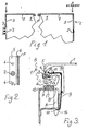
- Fig. 1 is a frontal view of door 1 provided with a hinge 2 at the right hand side of the drawing and a locking device 3 at the left hand side. Only the upper left and right hand corners are shown in order to clearly identify the gasket means P.
- the door is provided with no holes in the frontplate thereof and the hinge as well as the locking device are covered, i.e. protected, by the door in its closed position.
- FIG. 2 is a fragmentary view of the hinge side of the door 1 seen in a direction of an arrow C in FIG. 1. It appears from this figure that the _side wall 5 of the door has been provided at regular intervals with blanks 4 to be punched out thus permitting an optional location of a hinge.
- the door of the present invention is provided with such blanks in all four side walls which makes it possible during the mounting thereof to place the hinge at different sites in accordance with the different tasks to be undertaken.
- the door has to withstand heavy pressures (which is a special requirement in connection with possible explosions within switchboards) a number of hinges may be mounted which number corresponds to the actual task. It is a matter of course that similarly there has to be mounted a number of locking devices corresponding to the increased requirements. It also appears from FIG. 2 that the side walls of the door include and inwardly bent portion 6. This feature is especially important for obtaining a tight enclosure in connection with the hinge of the present invention and contributes additionally to the rigidity of the door.
- FIG. 3 illustrates the design of the hinge of the present invention. It shows a section through a pivot 2 and seen in the direction of an arrow A in FIG. 1.
- the hinge joint 14 includes two lugs which terminate in a hollow or U-shaped profile 8 which during the mounting process is put through an aperture 10 in the frame 12.
- the profile or terminating part 8 fits tightly into the frame but the hinge joint is also prevented from being pulled out by means of a spring means 9 one end 16 of which engages said terminating part 8.
- the centre of rotation of the door is represented by a rivet put through holes 11 in the pivot 2 and the two lugs of the hinge joint 14.
- the centre of rotation has been so positioned relative to the bent portion 6 of the side wall 5 of the door that a suitable impression is obtained in a sealing strip or gasket P provided on the frame when the door is closed.
- a normal to the frame 12 through the rivet in the hole 11 must pass the outer limitation 13 of the bent portion 6 of the door's side wall if a maximum impression into the gasket P is to be achieved along a line perpendicular to the plane of the drawing.
- the door is kept in a certain position when opened as indicated by dashed lines. This is achieved by the co-operation between a cone- shaped end of the pivot 2 and an outer end of spring means 9 as indicated at position 15.
- the same effect may be obtained if the spring means 9 is adapted to co-act similarly with the bent portion 6 of the door side wall 5. for most applications sufficient tightness of the door is obtained when the pivot 2 is simply run through a punched hole 4 in the side wall 5. However, a further sealing may be necessary, and this can be accomplished by means of a further gasket in the hole which gasket is compressed during the mounting of the hinge.
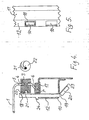
- FIG. 4 illustrates the design of a locking device of the present invention. It shows a section through the device seen in a direction of an arrow B in FIG. 1.
- the lock fittin comprises a U-shaped member 18 put through a hole 10 in the frame 12.
- FIG. 5 shows the frame 12 seen from the outside and the U-shaped member placed in the upper hole (on the drawing).
- the lock fitting fits tightly in the hole 10 with an abutment member 24 engaging the frame.
- the lock fitting is fixed by an inner bent part thereof. This may be achieved in a well defined manner at the inside of the frame 12 by providing cut outs or notches 19 in the side flanges of the U-shaped member thus permitting a bending of the bottom flange 23 only.
- the lock fitting comprises a locking cam 21 which, during the closing of the door, co-operates with a cam disc 22.
- the cam disc may be turned from the outside by turning the knob protruding from the punched hole 4 in the side wall 5 of the door 1. The turning may be carried out by means of a lever mounted in one of the holes 7 shown at the locking device 3 in FIG. 1.
- the cam disc is as shown provided with an Archimedes' spiral. However, it is evident that also other curves may be used.
- the bent part or edge 6 of the door's side wall 5 compresses the gasket P during the locking of the door thus obtaining the desired tightness.
- the gasket P is positioned in a small recess 17 in the frame 12. This feature facilitate the placing of the gasket straight on the frame to ensure that the straight compression of the gasket is located centrally of the gasket.
Landscapes
- Power Engineering (AREA)
- Engineering & Computer Science (AREA)
- Patch Boards (AREA)
- Casings For Electric Apparatus (AREA)
- Hinges (AREA)
- Connections By Means Of Piercing Elements, Nuts, Or Screws (AREA)
- Cultivation Receptacles Or Flower-Pots, Or Pots For Seedlings (AREA)
- Pretreatment Of Seeds And Plants (AREA)
- Surface Acoustic Wave Elements And Circuit Networks Thereof (AREA)
- Vending Machines For Individual Products (AREA)
- Ultra Sonic Daignosis Equipment (AREA)
- Structure Of Telephone Exchanges (AREA)
- Distribution Board (AREA)
Priority Applications (1)
| Application Number | Priority Date | Filing Date | Title |
|---|---|---|---|
| AT85102111T ATE60887T1 (de) | 1984-02-27 | 1985-02-26 | Wasserdichte tuer fuer elektrische schalttafel. |
Applications Claiming Priority (2)
| Application Number | Priority Date | Filing Date | Title |
|---|---|---|---|
| DK107584A DK158687C (da) | 1984-02-27 | 1984-02-27 | Taet laage til elektrisk fordelingsanlaeg |
| DK1075/84 | 1984-02-27 |
Publications (3)
| Publication Number | Publication Date |
|---|---|
| EP0154287A2 true EP0154287A2 (de) | 1985-09-11 |
| EP0154287A3 EP0154287A3 (en) | 1987-01-07 |
| EP0154287B1 EP0154287B1 (de) | 1991-02-13 |
Family
ID=8100716
Family Applications (1)
| Application Number | Title | Priority Date | Filing Date |
|---|---|---|---|
| EP85102111A Expired - Lifetime EP0154287B1 (de) | 1984-02-27 | 1985-02-26 | Wasserdichte Tür für elektrische Schalttafel |
Country Status (9)
| Country | Link |
|---|---|
| EP (1) | EP0154287B1 (de) |
| AT (1) | ATE60887T1 (de) |
| DE (1) | DE3581745D1 (de) |
| DK (2) | DK158687C (de) |
| FI (1) | FI84533C (de) |
| GR (1) | GR850502B (de) |
| IE (1) | IE56661B1 (de) |
| NO (1) | NO164450C (de) |
| PT (1) | PT80020B (de) |
Cited By (2)
| Publication number | Priority date | Publication date | Assignee | Title |
|---|---|---|---|---|
| EP0848468A1 (de) * | 1996-11-15 | 1998-06-17 | Siemens Aktiengesellschaft | Schaltschrank mit einer abgedichteten Tür |
| WO2008071308A1 (de) | 2006-12-12 | 2008-06-19 | Rittal Gmbh & Co. Kg | Schaltschrankanordnung |
Family Cites Families (4)
| Publication number | Priority date | Publication date | Assignee | Title |
|---|---|---|---|---|
| FR1140014A (fr) * | 1955-01-05 | 1957-07-09 | Bbc Brown Boveri & Cie | Tableaux d'appareillage en tôle pour les installations haute et basse tension |
| FR1305237A (fr) * | 1961-11-14 | 1962-09-28 | Therma Ag | Charnière pour portes d'armoires |
| DE1935444A1 (de) * | 1969-07-12 | 1971-01-14 | Heinze Fa R | Scharnier,insbesondere fuer Stahlmoebel |
| CH607598A5 (en) * | 1976-12-10 | 1978-09-15 | Sprecher & Schuh Ag | Dustproof housing, especially for electrical installations |
-
1984
- 1984-02-27 DK DK107584A patent/DK158687C/da active
-
1985
- 1985-02-25 IE IE466/85A patent/IE56661B1/xx unknown
- 1985-02-25 NO NO850751A patent/NO164450C/no unknown
- 1985-02-26 EP EP85102111A patent/EP0154287B1/de not_active Expired - Lifetime
- 1985-02-26 AT AT85102111T patent/ATE60887T1/de active
- 1985-02-26 DE DE8585102111T patent/DE3581745D1/de not_active Expired - Lifetime
- 1985-02-27 PT PT80020A patent/PT80020B/pt unknown
- 1985-02-27 GR GR850502A patent/GR850502B/el unknown
- 1985-02-27 FI FI850797A patent/FI84533C/fi not_active IP Right Cessation
- 1985-11-25 DK DK543785A patent/DK162669C/da not_active IP Right Cessation
Cited By (3)
| Publication number | Priority date | Publication date | Assignee | Title |
|---|---|---|---|---|
| EP0848468A1 (de) * | 1996-11-15 | 1998-06-17 | Siemens Aktiengesellschaft | Schaltschrank mit einer abgedichteten Tür |
| WO2008071308A1 (de) | 2006-12-12 | 2008-06-19 | Rittal Gmbh & Co. Kg | Schaltschrankanordnung |
| US8283576B2 (en) | 2006-12-12 | 2012-10-09 | Rittal Gmbh & Co. Kg | Hinges for control box enclosure |
Also Published As
| Publication number | Publication date |
|---|---|
| NO164450B (no) | 1990-06-25 |
| IE56661B1 (en) | 1991-10-23 |
| DK107584D0 (da) | 1984-02-27 |
| IE850466L (en) | 1985-08-27 |
| ATE60887T1 (de) | 1991-02-15 |
| DK543785D0 (da) | 1985-11-25 |
| NO164450C (no) | 1990-10-03 |
| FI850797L (fi) | 1985-08-28 |
| DK158687B (da) | 1990-07-02 |
| DK162669B (da) | 1991-11-25 |
| DE3581745D1 (de) | 1991-03-21 |
| DK158687C (da) | 1991-03-04 |
| EP0154287B1 (de) | 1991-02-13 |
| EP0154287A3 (en) | 1987-01-07 |
| PT80020B (pt) | 1987-05-29 |
| DK107584A (da) | 1985-08-28 |
| GR850502B (de) | 1985-06-27 |
| DK543785A (da) | 1985-11-25 |
| FI84533C (fi) | 1991-12-10 |
| DK162669C (da) | 1992-04-13 |
| NO850751L (no) | 1985-08-28 |
| PT80020A (en) | 1985-03-01 |
| FI84533B (fi) | 1991-08-30 |
| FI850797A0 (fi) | 1985-02-27 |
Similar Documents
| Publication | Publication Date | Title |
|---|---|---|
| US5435641A (en) | Cabinet for electrical equipment | |
| US6007353A (en) | Electrical connector enclosure | |
| US5259091A (en) | Hinge system for electrical enclosures | |
| US4890318A (en) | Building entrance terminal | |
| EP1070187B1 (de) | Rollstabsystem für einen mehrpunktriegel | |
| US4265365A (en) | Moisture resistant electrical outlet box | |
| US4794206A (en) | RF shielded and acoustic room | |
| EP0561293B1 (de) | Deckel für die Frontseite von elektrischen Schaltgeräten mit Kipphebelbetätigung, insbesondere Niederspannungs-Leistungsschaltern | |
| US4658422A (en) | Building entrance telephone terminal box | |
| DE2739783A1 (de) | Schutzkasten fuer elektrische instrumente auf schaltungsplatten | |
| US4862324A (en) | Switchgear enclosure and method of fabrication | |
| CA2047462A1 (en) | Sealed electrical switchgear cabinet | |
| US5713649A (en) | Method of manufacturing a box container or cabinet | |
| US6118071A (en) | Device for electrically connecting the frame or cabinet housing of a switching cabinet with the door | |
| EP1602158B1 (de) | Bausatz für eine steckvorrichtungs-kombination | |
| KR102442876B1 (ko) | 전기 외장용 폐쇄 장치, 및 그에 상응하는 전기 외장 | |
| US5853098A (en) | Repositioning backplate for an electrical outlet box | |
| EP0154287B1 (de) | Wasserdichte Tür für elektrische Schalttafel | |
| DE102007006055B4 (de) | Schaltpult | |
| DE3511901C2 (de) | ||
| DE19817386C2 (de) | Schaltschrank | |
| EP1330147B1 (de) | Modulares Steuerungsgehäuse | |
| EP0392700B1 (de) | Sicherheitstür | |
| EP0593106B1 (de) | Ein verdeckt angeordnetes Scharnier für ein Paneel einer Schalttafel | |
| US3787794A (en) | Top cover for a bus duct joint |
Legal Events
| Date | Code | Title | Description |
|---|---|---|---|
| PUAI | Public reference made under article 153(3) epc to a published international application that has entered the european phase |
Free format text: ORIGINAL CODE: 0009012 |
|
| AK | Designated contracting states |
Designated state(s): AT BE CH DE FR GB IT LI LU NL SE |
|
| PUAL | Search report despatched |
Free format text: ORIGINAL CODE: 0009013 |
|
| AK | Designated contracting states |
Kind code of ref document: A3 Designated state(s): AT BE CH DE FR GB IT LI LU NL SE |
|
| 17P | Request for examination filed |
Effective date: 19870209 |
|
| 17Q | First examination report despatched |
Effective date: 19880718 |
|
| GRAA | (expected) grant |
Free format text: ORIGINAL CODE: 0009210 |
|
| ITF | It: translation for a ep patent filed | ||
| AK | Designated contracting states |
Kind code of ref document: B1 Designated state(s): AT BE CH DE FR GB IT LI LU NL SE |
|
| PG25 | Lapsed in a contracting state [announced via postgrant information from national office to epo] |
Ref country code: NL Effective date: 19910213 Ref country code: LI Effective date: 19910213 Ref country code: FR Effective date: 19910213 Ref country code: CH Effective date: 19910213 Ref country code: BE Effective date: 19910213 Ref country code: AT Effective date: 19910213 |
|
| REF | Corresponds to: |
Ref document number: 60887 Country of ref document: AT Date of ref document: 19910215 Kind code of ref document: T |
|
| PG25 | Lapsed in a contracting state [announced via postgrant information from national office to epo] |
Ref country code: LU Free format text: LAPSE BECAUSE OF NON-PAYMENT OF DUE FEES Effective date: 19910228 |
|
| REF | Corresponds to: |
Ref document number: 3581745 Country of ref document: DE Date of ref document: 19910321 |
|
| REG | Reference to a national code |
Ref country code: CH Ref legal event code: PL |
|
| EN | Fr: translation not filed | ||
| NLV1 | Nl: lapsed or annulled due to failure to fulfill the requirements of art. 29p and 29m of the patents act | ||
| PLBE | No opposition filed within time limit |
Free format text: ORIGINAL CODE: 0009261 |
|
| STAA | Information on the status of an ep patent application or granted ep patent |
Free format text: STATUS: NO OPPOSITION FILED WITHIN TIME LIMIT |
|
| 26N | No opposition filed | ||
| ITPR | It: changes in ownership of a european patent |
Owner name: CESSIONE;HOLEC LK A/S |
|
| REG | Reference to a national code |
Ref country code: GB Ref legal event code: 732 |
|
| PGFP | Annual fee paid to national office [announced via postgrant information from national office to epo] |
Ref country code: DE Payment date: 19950116 Year of fee payment: 11 |
|
| PGFP | Annual fee paid to national office [announced via postgrant information from national office to epo] |
Ref country code: SE Payment date: 19950123 Year of fee payment: 11 |
|
| EAL | Se: european patent in force in sweden |
Ref document number: 85102111.3 |
|
| PGFP | Annual fee paid to national office [announced via postgrant information from national office to epo] |
Ref country code: GB Payment date: 19960115 Year of fee payment: 12 |
|
| PG25 | Lapsed in a contracting state [announced via postgrant information from national office to epo] |
Ref country code: DE Effective date: 19960123 |
|
| PG25 | Lapsed in a contracting state [announced via postgrant information from national office to epo] |
Ref country code: SE Effective date: 19960227 |
|
| PG25 | Lapsed in a contracting state [announced via postgrant information from national office to epo] |
Ref country code: GB Effective date: 19970226 |
|
| GBPC | Gb: european patent ceased through non-payment of renewal fee |
Effective date: 19970226 |