EP0154355B1 - Fabrication d'articles textiles à motif - Google Patents
Fabrication d'articles textiles à motif Download PDFInfo
- Publication number
- EP0154355B1 EP0154355B1 EP19850102970 EP85102970A EP0154355B1 EP 0154355 B1 EP0154355 B1 EP 0154355B1 EP 19850102970 EP19850102970 EP 19850102970 EP 85102970 A EP85102970 A EP 85102970A EP 0154355 B1 EP0154355 B1 EP 0154355B1
- Authority
- EP
- European Patent Office
- Prior art keywords
- yarn
- container
- containers
- row
- rows
- Prior art date
- Legal status (The legal status is an assumption and is not a legal conclusion. Google has not performed a legal analysis and makes no representation as to the accuracy of the status listed.)
- Expired
Links
- 238000004519 manufacturing process Methods 0.000 title description 6
- 239000004744 fabric Substances 0.000 title description 4
- 230000007246 mechanism Effects 0.000 claims description 16
- 238000000034 method Methods 0.000 claims description 15
- 239000000945 filler Substances 0.000 claims description 7
- 238000005056 compaction Methods 0.000 claims description 6
- 229940090046 jet injector Drugs 0.000 claims description 3
- 238000003825 pressing Methods 0.000 claims description 2
- 230000001419 dependent effect Effects 0.000 claims 1
- 238000000926 separation method Methods 0.000 claims 1
- 230000000694 effects Effects 0.000 description 4
- 235000004443 Ricinus communis Nutrition 0.000 description 3
- 239000003086 colorant Substances 0.000 description 3
- 240000000528 Ricinus communis Species 0.000 description 2
- 230000006835 compression Effects 0.000 description 2
- 238000007906 compression Methods 0.000 description 2
- 238000005304 joining Methods 0.000 description 2
- 241001239379 Calophysus macropterus Species 0.000 description 1
- 229910000831 Steel Inorganic materials 0.000 description 1
- 238000013459 approach Methods 0.000 description 1
- 230000003190 augmentative effect Effects 0.000 description 1
- 238000007599 discharging Methods 0.000 description 1
- 238000006073 displacement reaction Methods 0.000 description 1
- 238000009940 knitting Methods 0.000 description 1
- 230000000737 periodic effect Effects 0.000 description 1
- 230000002572 peristaltic effect Effects 0.000 description 1
- 239000010959 steel Substances 0.000 description 1
- 239000002699 waste material Substances 0.000 description 1
Images


Classifications
-
- D—TEXTILES; PAPER
- D03—WEAVING
- D03D—WOVEN FABRICS; METHODS OF WEAVING; LOOMS
- D03D39/00—Pile-fabric looms
- D03D39/02—Axminster looms, i.e. wherein pile tufts are inserted during weaving
-
- D—TEXTILES; PAPER
- D03—WEAVING
- D03J—AUXILIARY WEAVING APPARATUS; WEAVERS' TOOLS; SHUTTLES
- D03J1/00—Auxiliary apparatus combined with or associated with looms
-
- D—TEXTILES; PAPER
- D04—BRAIDING; LACE-MAKING; KNITTING; TRIMMINGS; NON-WOVEN FABRICS
- D04B—KNITTING
- D04B35/00—Details of, or auxiliary devices incorporated in, knitting machines, not otherwise provided for
- D04B35/22—Devices for preparatory treatment of threads
Definitions
- This invention relates to the supplying of yarn to a container, for example in the production of patterned fabrics and is concerned with the problems which arise as a result of the different usage rates of the yarns of different colours.
- a method is described in GB-A-1 421 621.
- These problems are associated with a wide variety of different production processes such as knitting, embroidery, lace-making, carpet making and so forth.
- the basic difficulty stems from the fact that at the end of a production run the quantity of yarn remaining in the creel will differ widely from colour to colour and in the majority of cases, this residual yarn will represent a source of waste which cannot normally be avoided.
- this is achieved by feeding each individual yarn between a pair of metering rollers followed by an air jet through which the yarn passes and which blows the yarn into the container and compacts it, the metering rollers being controlled to stop the feeding action when the required length of yarn has been supplied.
- each container is preferably formed with air outlet openings.
- the degree of compaction which is obtainable by air pressure is considerably less than the maximum which can be applied without introducing the risk of tangling. Accordingly, if the overall size of the individual containers represents a major factor in the operation of the creel, a stage of mechanical compression may be introduced after the feeding of the yarn is complete. This is most conveniently achieved by initially feeding the yarn to a first parallel-sided container which may be large enough to hold the required length of yarn when compacted only by air pressure. After filling, the yarn is compacted by mechanical pressure which forces it through the bottom of the container and into a second smaller container of similar cross section arranged below the first container. The second container can thus be of a height which is less than that of the first by a factor depending on the degree of compression. It is found in practice that the yarn can be compressed to about one third of its original volume and the height of the second container can therefore be correspondingly reduced.
- the bottom of the first container may be opened to allow the yarn to pass into the second container without interrupting the feeding of the yarn.
- the yarn may then be mechanically compacted in the normal way.
- a number of filling heads each comprising a pair of metering rollers and an air jet may be arranged in a row and operated simultaneously to supply yarn to a corresponding number of containers in one row of a group, the row of filling heads and the group of containers being indexed in relation to one another after the filling of each number of containers in a row in order to fill a corresponding number of containers in a subsequent row.
- the containers in a row may be spaced more closely than the filling heads, the latter may be spaced so as to fill alternate containers in a row, the group of containers being indexed in relation to the filling heads which are stationary by a distance equal to the pitch of the rows and, when alternate containers in all the rows have been filled, the group of containers is indexed laterally by a distance equal to the pitch of the containers in the rows and the sequence is repeated to fill all the remaining containers.
- Apparatus for supplying a predetermined length of yarn to a container in accordance with the invention comprises a pair of metering and feed rollers followed by an air jet injector for the yarn mounted above a support for the container, the rollers being controlled to stop their feeding action when the predetermined length of yarn has been injected into the container.
- the apparatus also includes means for mechanically compacting the yarn in the form of a ram with a central opening for the passage of the length of yarn which is in the process of being fed, so that the yarn is not broken by the descent of the ram.
- it preferably comprises a pair of hinged gates having operating mechanism for opening the gates in synchronism with the descent of the ram.
- the yarn may then be broken by the subsequent indexing movement by the inclusion of a gripper for holding the yarn extending from the top of each container in the creel after filling.
- a member for pressing each broken yarn end into a slot at the top of the respective container may also be provided.
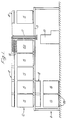
- a gripper Axminster carpet loom shown diagrammatically as 10 has a creel which is arranged in two levels, a floor level 11 and an upper level 12 mounted on a platform 13 extending above the loom.
- the tuft yarns held by the creel instead of being wound in packages in the usual way, are held in vertical tubular containers arranged in rectangular groups each mounted in a wheeled trolley 15.
- the individual yarns extend upwardly from each trolley, being illustrated only in connection with the trolley identified specifically as 15A where they are indicated generally as 16.
- Each yarn passes upwardly into its own individual tube, groups of which extend downwardly to the loom 10 at 17.
- each trolley 15 may include eighteen rows each of sixteen containers, giving a total of two hundred and eighty-eight yarns per trolley. For a particular pattern of carpet, there may be as many as thirty-two trolleys arranged in four rows of eight.
- each individual yarn container supplies yarn to a respective point in the pattern to be woven and thus, in the case of a gripper Axminster loom, as illustrated, each individual yarn is supplied to a respective yarn carrier.
- the length of yarn in each container is carefully controlled to correspond to that required for the respective position in the pattern and the remainder of the description is concerned with the apparatus used for supplying each container of a group mounted in a trolley with the appropriate length of yarn.
- Figure 1 has been related specifically to a gripper Axminster carpet loom, it will be understood that similar principles apply to the production of other types of patterned fabric where individual yarn supplies are directed to respective points in the pattern.
- Figure 1 illustrates all the yarns as being held in containers, it is quite possible that at least a small proportion of the yarns, particularly where relatively large quantities are required, should be wound on packages in the usual way, butthis is not illustrated in the drawings.
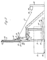
- FIG. 2 shows the general arrangement of apparatus for this purpose.
- a typical arrangement of containers in a trolley 15 comprises eighteen rows, each of sixteen containers.
- each container may be 85 mm square and 1200 mm long with a wall thickness of 1.5 mm.
- the apparatus seen in Figures 2 and 3 includes only eight filler heads, each indicated generally as 20 and only one of which is seen in Figure 2.
- the filler heads 20 are spaced so as to fill alternate containers 21 and in operation, a trolley 15 is indexed through the apparatus by means of mechanism to be described later so as to supplyyarn to alternate containers in each of the eighteen rows (to quote the example referred to previously) and when this operation is complete, the trolley 15 is indexed laterally by a distance equal to the pitch of containers in the rows and the process is repeated so as to supply yarn to all the intervening containers.
- the yarns supplied to the containers 21 are drawn from packages, one of which is seen at 25, mounted on a frame 26.
- the yarn shown as 27 passes through guides 28 and 29 and thence to a pair of metering rollers 30 and 31 seen in more detail in the enlarged view of Figure 4.
- the lower roller 30 is made of steel and is positively driven while the roller 31 is rubber covered to avoid slip and is pressed against the roller 30 by an air cylinder 32 seen in Figure 2.
- the metering action is performed by the upper roller 31 which is controlled by a computer produced tape or other form of information store corresponding to the respective position in the pattern.
- the roller 31 is raised to stop the feed. If yarn is not required in any particular container, the respective roller 31 remains in the up position.
- the yarn 27 After passing between the rollers 30 and 31, the yarn 27 passes downwardly through an air injec- teor jet indicated generally as 35 in Figure 4 and seen in more detail in Figure 10 which will be described later.
- the effect of the air jet is to maintain the downward movement of the yarn 27 and, more importantly, to supply compressed air to the interior of a first or upper container 40 to which the yarn is supplied so as to have a compacting effect on the yarn as it accumulates towards the bottom of the container.
- the yarn accumulates in random fashion at the bottom of each container 40 and the compacting effect of the compressed air from the jet 35 is augmented by periodic pulses of higher pressure air.
- the pressure at the jet may be normally between twenty and thirty pounds per square inch (137-206 kN/m 2 ) but this is increased to a pressure of eighty pounds per square inch (551 kN/m 2 ) for example at intervals of about two seconds. This sudden increase in pressure has the effect of acting on the top of the packed yarn and compacting the body of the yarn beneath.
- the pulses of increased pressure may conveniently be obtained by charging an air reservoir at the increased pressure referred to and then abruptly discharging the air by way of a valve into the main airstream of the jet.
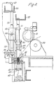
- each upper container 40 The amount of yarn fed into each upper container 40 is controlled individually as described above, but in general (with an exception to be mentioned later) does not fill the container above a point just below the ram 42 seen in Figure 4 which is formed with a central opening 43 for the passage of the yarn.
- the ram 42 is carried by four vertical rods 44 passing through seals 45 in the top 46 of the container 40, as seen in Figure 11 and described in more detail later.
- the upper ends of the rods 44 are fixed to a crosshead 50 which slides vertically on a guide rod 51 extending downwardly from a support 52 and controlled by an air motor 53.
- the air motor 53 runs on a vertical guide 54 extending between supprts 55 and 56.
- a suitable type of such motor is one available commercially under the name ROL-AIR MOTA sold by Kay Pneumatics Limited.
- This motor operates on a peristaltic principle which utilises a pair of nipping rollers indicated diagrammatically as 58 which co-operate with an air hose constituting the guide 54. Air pressure is supplied to opposite ends of the hose by way of lines 59 and 60 connected to a reversing valve.
- each upper container 40 is constituted by a pair of gates 61 each extending from a bush 62 turning about an axle 63, the angular position of which is controlled by an arm 64, the other end of which is connected to the piston rod 65 of an air cylinder 66.
- the gates 61 In the full line position of the gates 61, they resist the downward pressure exerted by the ram 42 so that the yarn is compacted as previously described.
- the ram 42 has just operated to force the compacted yarn into the container 21 and has returned to its uppermost position (not seen).
- the position of the ram illustrated in Figure 6 corresponds to the maximum compaction of the quantity of yarn which has been fed to the upper container 40 and at this point, the air cylinders 66 are operated to swing the gates 61 downwardly into the vertical positions shown in dotted lines as 61'. This allows the compacted body of yarn to pass downwardly into the container 21 which is of the same cross section as the container 40 and is in register with it as a result of indexing movement of the trolley 15 on which it is mounted.
- the downward movement of the ram 42 then continues until all the compacted yarn has been forced into the container 21 except for a length of yarn which extends upwardly from the compacted mass, through the opening 43 into the ram 42 and back to the rollers 30 and 31.
- the ram 42 then returns upwardly to its initial position and the gates 61 return to the full-line, closed position of Figure 5 so as to clamp the length of yarn between them.
- the individual rams 42 operate independently of one anther, their time of operation depending on the quantity of yarn to be transferred from an upper container 40 to a lower container 21. If no yarn at all is to be supplied to any particular container, the respective ram does not operate at all.
- any lower container 21 is required to accommodate a particularly large quantity of yarn, that is to say more than can be held by an upper container 40, a modified form of operation is necessary.
- the gates 61 are opened without interrupting the feed of yarn.
- the yarn already in the container 40 is thus allowed to drop into the corresponding lower container 21, the movement being assisted by the air pressure.
- each container 40 is consideralby longer than the respective lower container 21, the plug of yarn spans the gap between the two containers and filling of the upper container 40 proceeds as previously.
- the ram 42 operates in the same manner as previously described, compressing the complete body of yarn and forcing it all into the lower container 21. The ram 42 then returns and the gates 61 close, as previously described.
- the opening of the gates 61 is controlled on a time basis, i.e. by means of a signal from an electrical timer rather than in response to a signal that the correct amount of yarn has been supplied to the upper container.
- this timing corresponds to a point when the container 40 is approximately two-thirds full.
- feeding of the yarn continues without interruption and the final operation of the ram 42 to compress all the yarn into the lower container 21 takes place in exactly the same manner as previously described.
- This modified mode of operation represents the exception referred to above in which the total quantity of yarn supplied is greater than that which would normally fill a container 40 without mechanical compaction.
- a pusher member 82 mounted for vertical movement in guides (not shown) as indicated by the double headed arrow in Figure 6 is controlled to move from an upper position shown in Figure 5 to a lower position shown in Figure 6 in which a forked end portion 83 engages the length of yarn 70 and presses it into a small notch in the top of the wall of the container 21.
- Each container has such a notch, as can be seen at 84 in Figures 5 and 6. This notch is sufficiently narrow to grip the yarn end and the pusher member 82 is then retracted to leave the yarn end held in position, after which it is released by opening of the jaws 72, 73 of the gripper mechanism 71.
- Each filled container 21 in the trolley 15 is thus left with a projecting yarn end held in the notch 84 and these ends are thus readily available for joining to the yarn ends projecting from the tubes 18 of the creel, as previously described. After joining, it is a simple matter to pull each yarn through its tube for piecing up in the respective yarn carrier of the loom.
- FIG 8 shows further details of the gates 61 in the open position indicated as 61' in Figure 5.
- the gates are perforated to allow free passage of the air which is blown into each upper container 40 to compact the yarn against the gate 61 at the bottom of each container.
- the walls of the containers themselves are impervious and the air which flows downwardly through the compacted mass of yarn must therefore be able to escape freely through the gates 61.
- Figures 9 to 12 shown constructional details of the air jet 35 and the ram 42 at the upper end of each upper container 40.
- the injector air jet 35 includes a central passage 86 for the passage of yarn which broadens out at 87, air being supplied to this broader part by an inclined passage 88 leading from an annular space 89. Air is supplied to the space 89 by a line 90 provided with a screw connection 91. The flow of air down the passage 88 assists the movement of the yarn through the passage 86 and the resultant air pressure within the container 40 compacts the yarn at the bottom.
- the ram 42 as seen from Figures 9 and 12 is square in shape to match the shape of the cross section of the container 40 and has an appreciable clearance from the wall of the container to avoid the risk of compacted yarn becoming jammed.
- the central opening 43 is circular to avoid any corners which might trap the yarn.
- each trolley is provided with a swivel castor 95 at each corner and remains supported on these castors during the successive stages of filling and indexing.
- each trolley is connected to an indexing frame 100 by means of a pair of pegs 101 which are moved upwardly to engage corresponding holes close to the forward corners of each trolley, best seen in Figure 13.
- Each peg 101 is mounted for vertical movement in a corresponding socket in structure 102 mounted beneath the frame 100 and is controlled for movement in its socket by connection to an arm 103 fixed to a shaft 104 which extends across the width of the indexing frame 100 to control both pegs 101.
- the shaft 104 is rocked between its two positions by means of an arm 105 which is itself operated by an air cylinder 106.
- the frame 100 is supported at each side by rollers 110 running between lower and upper rails 111 and 112 fixed to the main frame of the apparatus.
- the frame is indexed from left to right as seen in Figures 2 and 13 by means of a drive chain 114 passing around sprockets 115 and 116.
- the sprockets 116 on each side are driven in steps by a chain drive 117 by means of a electric motor 118 operating through a clutch/brake unit 119 and a speed reducing gear box 120 to produce the necessary indexing motion from left to right.
- the position of the trolley 15 in relation to the frame 100 is constantly monitored by a detector arm 140 which is pivoted to the frame 100 and biased against the front of the trolley.
- the upper end of the arm 140 carries a micro-switch 141 which controls the clutch/brake 119 and cooperates with a bar 142 formed with spaced projections 143.
- the pitch of the projections 143 is equal to the required indexing distance and each time the plunger of the micro-switch engages a projection 143, indexing movement is interrupted.
- the first step of movement brings the first row of containers 21 in the trolley 15 into register beneath the filling containers 40 and each successive step of indexing brings the next row of containers 21 into this position.
- each step of indexing is associated with breakage of the yarns from the filled containers so that, after the last row of containers has been filled, one further step of indexing is required in order to break the yarns from the last row of containers.
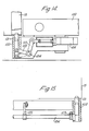
- the cross indexing mechanism is illlstrated in Figure 16 and 17.
- the structure 102 defining the socket for reception of each peg 101 is mounted for horizontal sliding motion on a bar 121 extending between pairs of brackets 122 extending downwardly from the frame 100.
- the members 102 are inter-connected for this sliding movement by a bar 124 which slides through the brackets 122 and has a projecting portion 125 to which is pivoted a connecting rod 126 driven by an eccentric 127.
- the eccentric 127 forms part of a gear wheel 128 meshing with a smaller pinion 129 which, in its turn, is driven by an electric motor 130 by way of a clutch/brake unit 131 and a speed reducing gear box 132.
Landscapes
- Engineering & Computer Science (AREA)
- Textile Engineering (AREA)
- Unwinding Of Filamentary Materials (AREA)
- Warping, Beaming, Or Leasing (AREA)
- Looms (AREA)
Claims (18)
Applications Claiming Priority (2)
| Application Number | Priority Date | Filing Date | Title |
|---|---|---|---|
| GB8103564 | 1981-02-05 | ||
| GB8103564 | 1981-02-05 |
Related Parent Applications (1)
| Application Number | Title | Priority Date | Filing Date |
|---|---|---|---|
| EP82300372.8 Division | 1982-01-26 |
Publications (3)
| Publication Number | Publication Date |
|---|---|
| EP0154355A2 EP0154355A2 (fr) | 1985-09-11 |
| EP0154355A3 EP0154355A3 (en) | 1987-04-01 |
| EP0154355B1 true EP0154355B1 (fr) | 1989-10-25 |
Family
ID=10519468
Family Applications (2)
| Application Number | Title | Priority Date | Filing Date |
|---|---|---|---|
| EP19820300372 Expired EP0058478B1 (fr) | 1981-02-05 | 1982-01-26 | Fabrication d'articles textiles à motif |
| EP19850102970 Expired EP0154355B1 (fr) | 1981-02-05 | 1982-01-26 | Fabrication d'articles textiles à motif |
Family Applications Before (1)
| Application Number | Title | Priority Date | Filing Date |
|---|---|---|---|
| EP19820300372 Expired EP0058478B1 (fr) | 1981-02-05 | 1982-01-26 | Fabrication d'articles textiles à motif |
Country Status (5)
| Country | Link |
|---|---|
| EP (2) | EP0058478B1 (fr) |
| AU (2) | AU558612B2 (fr) |
| DE (1) | DE3272954D1 (fr) |
| IE (1) | IE52692B1 (fr) |
| NZ (1) | NZ199572A (fr) |
Families Citing this family (5)
| Publication number | Priority date | Publication date | Assignee | Title |
|---|---|---|---|---|
| GB9508197D0 (en) * | 1995-04-21 | 1995-06-07 | Brintons Ltd | Yarn supply |
| EP1156146A1 (fr) | 2000-05-15 | 2001-11-21 | Brintons Limited | Métier pour tapis |
| AU2013302838B2 (en) | 2012-08-14 | 2017-06-01 | Invista Technologies S.A.R.L. | Yarn packaging and delivery system |
| EP3838823B1 (fr) * | 2019-12-19 | 2025-10-29 | Aladdin Manufacturing Corporation | Récipient de stockage de fil et système de stockage de fil |
| WO2022032116A2 (fr) * | 2020-08-06 | 2022-02-10 | Shaw Industries Group, Inc. | Procédés et dispositifs de transport de fil |
Family Cites Families (6)
| Publication number | Priority date | Publication date | Assignee | Title |
|---|---|---|---|---|
| GB1310029A (en) * | 1970-08-24 | 1973-03-14 | Ici Ltd | Packaging filamentary tows |
| CS151907B1 (fr) * | 1970-09-18 | 1973-12-19 | ||
| GB1421621A (en) * | 1973-01-25 | 1976-01-21 | British Carpets Ltd | Making carpets |
| NL160344C (nl) * | 1974-05-15 | Nissan Motor | Inrichting voor het aanvoeren en afmeten van de inslagdraad in een weefgetouw. | |
| NL7600569A (nl) * | 1976-01-20 | 1977-07-22 | Rueti Te Strake Bv | Weefmachine met een pneumatisch bediende buffer- inrichting voor het inslaggaren. |
| US4244309A (en) * | 1979-08-30 | 1981-01-13 | Abram N. Spanel | Method, means, and tufted product |
-
1982
- 1982-01-25 IE IE14882A patent/IE52692B1/en not_active IP Right Cessation
- 1982-01-26 EP EP19820300372 patent/EP0058478B1/fr not_active Expired
- 1982-01-26 DE DE8282300372T patent/DE3272954D1/de not_active Expired
- 1982-01-26 EP EP19850102970 patent/EP0154355B1/fr not_active Expired
- 1982-01-27 NZ NZ19957282A patent/NZ199572A/en unknown
- 1982-01-28 AU AU79942/82A patent/AU558612B2/en not_active Expired
-
1985
- 1985-10-21 AU AU48900/85A patent/AU570135B2/en not_active Expired
Also Published As
| Publication number | Publication date |
|---|---|
| AU570135B2 (en) | 1988-03-03 |
| EP0154355A3 (en) | 1987-04-01 |
| AU4890085A (en) | 1986-04-10 |
| EP0058478B1 (fr) | 1986-09-03 |
| IE820148L (en) | 1982-08-05 |
| EP0154355A2 (fr) | 1985-09-11 |
| IE52692B1 (en) | 1988-01-20 |
| EP0058478A1 (fr) | 1982-08-25 |
| AU558612B2 (en) | 1987-02-05 |
| NZ199572A (en) | 1985-08-16 |
| AU7994282A (en) | 1982-08-12 |
| DE3272954D1 (en) | 1986-10-09 |
Similar Documents
| Publication | Publication Date | Title |
|---|---|---|
| US4051652A (en) | Method and apparatus for packaging yarn packages doffed from a yarn producing machine | |
| DE69508936T2 (de) | Vorrichtung und verfahren zum anbringen von tuftinggarnen auf einen tuftinggarnträger | |
| EP0154355B1 (fr) | Fabrication d'articles textiles à motif | |
| US3854275A (en) | Mechanized bobbin handler | |
| US3999476A (en) | Closed chamber baler | |
| DE2233283A1 (de) | Vorrichtung zum zufuehren von materialstraengen | |
| US4718336A (en) | Modular automatic bale tier | |
| US3119212A (en) | Tow packaging | |
| IE52693B1 (en) | Production of patterned fabrics | |
| US3164946A (en) | Doffing and donning mechanism | |
| DE4029464C2 (de) | Verfahren und Vorrichtung zum Austragen von Auflaufspulen aus einer Streck-Falschdrahtzwirnmaschine | |
| US3996720A (en) | Yarn cutting and packaging machine | |
| US3765160A (en) | Mechanized bobbin handler | |
| US3547575A (en) | Apparatus and method for fluid injection of yarn packages | |
| CH398455A (de) | Fördereinrichtung zum Befördern von aus zumindest zwei Austrittsstellen von ersten Maschinen austretenden Gegenständen zu einer nachgeschalteten Maschine, insbesondere für Verpackungsmaschinen | |
| DE3918064C2 (fr) | ||
| DE1581087C3 (de) | Fördereinrichtung zum Befördern von aus mindestens zwei Maschinen austretenden Gegenständen zu einer nachgeschalteten Maschine | |
| US5273078A (en) | Rod-type three-dimensional loom and continuous operating method | |
| US3081798A (en) | Apparatus for weaving wire cloth | |
| US3245214A (en) | Automatic device for removing full bobbins from continuous spinning and like machines | |
| GB1083191A (en) | Device for loading and unloading spindles on spinning or doubling machines | |
| CN115180236B (zh) | 一种用于筒纱包装的全自动制袋供袋系统 | |
| US3694288A (en) | Method for the fabrication of nail plates and apparatus for the performance of the aforesaid method | |
| CN111874749A (zh) | 蚕丝辊料供料系统 | |
| US3158897A (en) | Machine for shaping a fabric sheet unit to form a sheath for storage battery plates |
Legal Events
| Date | Code | Title | Description |
|---|---|---|---|
| PUAI | Public reference made under article 153(3) epc to a published international application that has entered the european phase |
Free format text: ORIGINAL CODE: 0009012 |
|
| 17P | Request for examination filed |
Effective date: 19850524 |
|
| AC | Divisional application: reference to earlier application |
Ref document number: 58478 Country of ref document: EP |
|
| AK | Designated contracting states |
Designated state(s): BE DE GB NL |
|
| PUAL | Search report despatched |
Free format text: ORIGINAL CODE: 0009013 |
|
| AK | Designated contracting states |
Kind code of ref document: A3 Designated state(s): BE DE GB NL |
|
| 17Q | First examination report despatched |
Effective date: 19881219 |
|
| GRAA | (expected) grant |
Free format text: ORIGINAL CODE: 0009210 |
|
| AC | Divisional application: reference to earlier application |
Ref document number: 58478 Country of ref document: EP |
|
| AK | Designated contracting states |
Kind code of ref document: B1 Designated state(s): BE DE GB NL |
|
| REF | Corresponds to: |
Ref document number: 3280001 Country of ref document: DE Date of ref document: 19891130 |
|
| PLBE | No opposition filed within time limit |
Free format text: ORIGINAL CODE: 0009261 |
|
| STAA | Information on the status of an ep patent application or granted ep patent |
Free format text: STATUS: NO OPPOSITION FILED WITHIN TIME LIMIT |
|
| 26N | No opposition filed | ||
| PGFP | Annual fee paid to national office [announced via postgrant information from national office to epo] |
Ref country code: DE Payment date: 20010122 Year of fee payment: 20 |
|
| PGFP | Annual fee paid to national office [announced via postgrant information from national office to epo] |
Ref country code: GB Payment date: 20010124 Year of fee payment: 20 |
|
| PGFP | Annual fee paid to national office [announced via postgrant information from national office to epo] |
Ref country code: NL Payment date: 20010131 Year of fee payment: 20 |
|
| PGFP | Annual fee paid to national office [announced via postgrant information from national office to epo] |
Ref country code: BE Payment date: 20010313 Year of fee payment: 20 |
|
| BE20 | Be: patent expired |
Free format text: 20020126 *BRINTONS LTD |
|
| REG | Reference to a national code |
Ref country code: GB Ref legal event code: IF02 |
|
| PG25 | Lapsed in a contracting state [announced via postgrant information from national office to epo] |
Ref country code: GB Free format text: LAPSE BECAUSE OF EXPIRATION OF PROTECTION Effective date: 20020125 |
|
| PG25 | Lapsed in a contracting state [announced via postgrant information from national office to epo] |
Ref country code: NL Free format text: LAPSE BECAUSE OF EXPIRATION OF PROTECTION Effective date: 20020126 |
|
| REG | Reference to a national code |
Ref country code: GB Ref legal event code: PE20 Effective date: 20020125 |
|
| NLV7 | Nl: ceased due to reaching the maximum lifetime of a patent |