EP0154422A2 - Trépan de forage rotatif - Google Patents
Trépan de forage rotatif Download PDFInfo
- Publication number
- EP0154422A2 EP0154422A2 EP85300890A EP85300890A EP0154422A2 EP 0154422 A2 EP0154422 A2 EP 0154422A2 EP 85300890 A EP85300890 A EP 85300890A EP 85300890 A EP85300890 A EP 85300890A EP 0154422 A2 EP0154422 A2 EP 0154422A2
- Authority
- EP
- European Patent Office
- Prior art keywords
- carrier
- socket
- drill bit
- bit according
- periphery
- Prior art date
- Legal status (The legal status is an assumption and is not a legal conclusion. Google has not performed a legal analysis and makes no representation as to the accuracy of the status listed.)
- Granted
Links
Images

Classifications
-
- E—FIXED CONSTRUCTIONS
- E21—EARTH OR ROCK DRILLING; MINING
- E21B—EARTH OR ROCK DRILLING; OBTAINING OIL, GAS, WATER, SOLUBLE OR MELTABLE MATERIALS OR A SLURRY OF MINERALS FROM WELLS
- E21B10/00—Drill bits
- E21B10/46—Drill bits characterised by wear resisting parts, e.g. diamond inserts
- E21B10/56—Button-type inserts
- E21B10/567—Button-type inserts with preformed cutting elements mounted on a distinct support, e.g. polycrystalline inserts
- E21B10/573—Button-type inserts with preformed cutting elements mounted on a distinct support, e.g. polycrystalline inserts characterised by support details, e.g. the substrate construction or the interface between the substrate and the cutting element
-
- E—FIXED CONSTRUCTIONS
- E21—EARTH OR ROCK DRILLING; MINING
- E21B—EARTH OR ROCK DRILLING; OBTAINING OIL, GAS, WATER, SOLUBLE OR MELTABLE MATERIALS OR A SLURRY OF MINERALS FROM WELLS
- E21B10/00—Drill bits
- E21B10/62—Drill bits characterised by parts, e.g. cutting elements, which are detachable or adjustable
-
- Y—GENERAL TAGGING OF NEW TECHNOLOGICAL DEVELOPMENTS; GENERAL TAGGING OF CROSS-SECTIONAL TECHNOLOGIES SPANNING OVER SEVERAL SECTIONS OF THE IPC; TECHNICAL SUBJECTS COVERED BY FORMER USPC CROSS-REFERENCE ART COLLECTIONS [XRACs] AND DIGESTS
- Y10—TECHNICAL SUBJECTS COVERED BY FORMER USPC
- Y10T—TECHNICAL SUBJECTS COVERED BY FORMER US CLASSIFICATION
- Y10T29/00—Metal working
- Y10T29/49—Method of mechanical manufacture
- Y10T29/49826—Assembling or joining
- Y10T29/49863—Assembling or joining with prestressing of part
- Y10T29/49876—Assembling or joining with prestressing of part by snap fit
-
- Y—GENERAL TAGGING OF NEW TECHNOLOGICAL DEVELOPMENTS; GENERAL TAGGING OF CROSS-SECTIONAL TECHNOLOGIES SPANNING OVER SEVERAL SECTIONS OF THE IPC; TECHNICAL SUBJECTS COVERED BY FORMER USPC CROSS-REFERENCE ART COLLECTIONS [XRACs] AND DIGESTS
- Y10—TECHNICAL SUBJECTS COVERED BY FORMER USPC
- Y10T—TECHNICAL SUBJECTS COVERED BY FORMER US CLASSIFICATION
- Y10T29/00—Metal working
- Y10T29/49—Method of mechanical manufacture
- Y10T29/49826—Assembling or joining
- Y10T29/49945—Assembling or joining by driven force fit
Definitions
- the invention relates to rotary drill bits for use in drilling or coring deep holes in subsurface formations and, in particular, to arrangements for mounting cutting members in such bits.
- Rotary drill bits of the kind to which the invention relates comprise a bit body having a shank for connection to a drill string and an inner passage for supplying drilling fluid to the face of the bit.
- the bit body carries a plurality of cutting elements.
- Each cutting element may comprise a circular preform having a thin hard facing layer, which defines the front cutting face of the element, bonded to a less hard backing layer.
- the hard facing layer may be formed of polycrystalline diamond or other superhard material
- the backing layer may be formed of cemented tungsten carbide.
- the two-layer arrangement of the cutting elements provides a degree of self-sharpening since, in use, the less hard backing layer wears away more easily than the harder cutting layer.
- single layer preforms are also known and have the advantage that they may be thermally stable.
- the cutting elements are mounted on the bit body by being bonded, for example by brazing, to a carrier which may be in the form of a stud of tungsten carbide which is received and located in a socket in the bit body which may be formed, for example, from steel or from a tungsten carbide matrix.
- the studs on which the cutting elements are mounted are secured within their respective sockets by brazing, press fitting or shrink fitting.
- press fitting and shrink fitting are suitable for steel bit bodies where the sockets may be fairly accurately machined, difficulties arise in using such methods with a matrix body.
- the sockets are usually moulded in the surface of the bit body at the same time as the bit body is formed.
- the present invention sets out to provide an improved form of mounting for the carriers of preform cutting elements in a bit body.
- a rotary drill bit for use in drilling or coring deep holes in subsurface formations, comprising a bit body having a shank for connection to a drill string, a plurality of cutting elements mounted at the surface of the bit body, and a channel in the bit body for supplying drilling fluid to the surface of the bit body, at least some of the cutting elements each being mounted on a carrier which is received in a socket in the bit body, there being provided within the socket and disposed around at least a portion of the periphery of the carrier resiliently compressible retaining means which are formed separately from the carrier and bit body and are resiliently compressed between the carrier and the wall of the socket so as frictionally to retain the carrier in the socket.
- resiliently compressible retaining means permits greater tolerances in the relative dimensions of the socket and carrier and the invention is thus particularly suitable for use with matrix body bits where the sockets are moulded.
- Said retaining means preferably comprise an arcuate element extending around a portion of the periphery of the carrier.
- the arcuate element is also preferably pre-shaped to conform substantially to the portion of the periphery of the carrier which it engages.
- the arcuate element may extend around only a portion of the periphery of the carrier, it preferably extends around substantially the whole periphery of the carrier.
- the arcuate element may be formed from metal which is corrugated to provide the resilience thereof.
- the corrugations may extend substantially parallel to the central axis of the carrier.
- the arcuate element may be formed from material which is inherently resiliently compressible so that said material substantially fills the space between the portion of the carrier around which it extends and the wall of the socket.
- the retaining means comprise a plurality of separate resiliently compressible elements disposed side-by-side around at least a portion of the periphery of the carrier.
- the internal wall of the socket is preferably formed with a recess in which said retaining means are at least partly located.
- said recess may comprise an annular groove extending around the whole-periphery of wall of the socket.
- the carrier itself may be formed with a recess in which the retaining means are at least partly located, and particularly in the case where the retaining means extend around substantially the whole periphery of the carrier, the recess may be an annular groove which also extends around the whole periphery of the carrier.
- the bit body 10 is typically formed of carbide matrix infiltrated with a binder alloy, and has a threaded shank 11 at one end for connection to the drill string.
- the operative end face 12 of the bit body is formed with a number of blades 13 radiating from the central area of the bit and the blades carry cutting members 14 spaced apart along the length thereof.
- the bit gauge section 15 includes kickers 16 which contact the walls of the bore hole to stabilise the bit in the bore hole.
- a central passage (not shown) in the bit body and shank delivers drilling fluid through nozzles 17 in the end face 12, in known manner.
- each cutting member 14 comprises a preform cutting element 18 mounted on a carrier 19 in the form of a stud which is located in a socket 20 in the bit body 10.
- each preform cutting element 18 is usually circular and comprises a thin facing layer 21 of polycrystalline diamond bonded to a backing layer 22 of tungsten carbide, both layers being of uniform thickness.
- the rear surface of the backing layer 22 is bonded, for example by brazing, to a suitably orientated surface on the stud 19 which may also be formed from tungsten carbide.
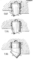
- the stud 19 is conventionally of circular cross-section as is also the corresponding socket 20.
- the socket 20 is formed adjacent the bottom wall 23 thereof with a peripheral annular groove 24 which extends axially but is spaced inwardly of the mouth of the socket.
- a corrugated metal tolerance ring 25 Located within the groove 24 is a corrugated metal tolerance ring 25 which is in the form of a collar substantially wholly encircling the stud 19.
- the overall radial thickness of the ring 25, provided by the depth of the corrugations in the ring, is such that the ring is compressed radially between the adjacent surface of the stud 19 and the peripheral surface of the annular groove 24.
- the dimensions of the tolerance ring are so chosen as to accommodate tolerances in the dimensions of the socket and stud 19 to ensure that the stud 19 is retained by an interference fit in the socket.
- annular groove 24 is spaced part-way between the mouth of the socket 20 and the bottom wall 23 thereof. Otherwise the arrangement is similar to that shown in Figure 3.
- the stud 19 is formed with a peripheral recess 26 at the end thereof remote from the cutting element 18 (which, in this instance, is generally wedge-shaped in cross-section).
- the recess 26 serves to accommodate the tolerance ring 25.
- the tolerance ring may be wholly located within the recess 26, the socket being generally cylindrical, or the socket may also be formed, as shown, with an annular peripheral groove 24 which registers with the recess 26 on the stud 19 so that the tolerance ring projects partly into the recess on the stud and partly into the groove in the socket.
- the required resilient retaining means may be provided by a number of separate elements, such as axially extending roll pins, disposed side-by-side around at least part of the periphery of the stud.
- the tolerance ring 25 may comprise a known form of split ring where the corrugations extend axially over the major part of the axial depth of the ring and are disposed parallel and side-by-side around the periphery of the ring.
- Such tolerance rings are conventionally used for securing elements to rotating shafts, but it has been discovered that they are also particularly suitable for use for the purposes according to the invention.
- such tolerance rings are acting in quite a different manner from their conventional use, since their normal primary function is to restrain relative rotation between the element and shaft with which they are used, whereas in the present invention there is little tendency for the stud to rotate about its central axis with respect to the socket, and the ring serves to restrain axial displacement of the stud from the socket.
- the ring or other arcuate element may be formed from material which is inherently resiliently compressible so that it substantially fills the space between the stud 19 and the encircling wall of the socket.
- the dimensions of the retaining means, and the degree of its resilient compressibility, are such that the carriers or studs are adequately retained within their sockets solely by frictional engagement.
- one conventional method of retaining the studs in their sockets has been by brazing, and in such methods it is known, in some cases, to retain the carriers or studs in their sockets, prior to brazing, by the use of resilient elements, such as one or more roll pins. It will be appreciated, however, that in such cases the retaining function of the pins is purely temporary, and the relative dimensions and resilience characteristics of the components are not sufficient alone to ensure adequate retention of the carriers in the sockets during the use of the drill bit. Such known arrangements do not therefore fall within the scope of the present invention.
Landscapes
- Engineering & Computer Science (AREA)
- Geology (AREA)
- Mining & Mineral Resources (AREA)
- Life Sciences & Earth Sciences (AREA)
- General Life Sciences & Earth Sciences (AREA)
- Fluid Mechanics (AREA)
- Environmental & Geological Engineering (AREA)
- Physics & Mathematics (AREA)
- Mechanical Engineering (AREA)
- Geochemistry & Mineralogy (AREA)
- Chemical & Material Sciences (AREA)
- Crystallography & Structural Chemistry (AREA)
- Earth Drilling (AREA)
- Holo Graphy (AREA)
- Surgical Instruments (AREA)
- Drilling Tools (AREA)
Applications Claiming Priority (2)
| Application Number | Priority Date | Filing Date | Title |
|---|---|---|---|
| GB8405180 | 1984-02-28 | ||
| GB848405180A GB8405180D0 (en) | 1984-02-28 | 1984-02-28 | Rotary drill bits |
Publications (3)
| Publication Number | Publication Date |
|---|---|
| EP0154422A2 true EP0154422A2 (fr) | 1985-09-11 |
| EP0154422A3 EP0154422A3 (en) | 1986-06-11 |
| EP0154422B1 EP0154422B1 (fr) | 1989-04-12 |
Family
ID=10557289
Family Applications (1)
| Application Number | Title | Priority Date | Filing Date |
|---|---|---|---|
| EP85300890A Expired EP0154422B1 (fr) | 1984-02-28 | 1985-02-11 | Trépan de forage rotatif |
Country Status (6)
| Country | Link |
|---|---|
| US (1) | US4700790A (fr) |
| EP (1) | EP0154422B1 (fr) |
| CA (1) | CA1241945A (fr) |
| DE (1) | DE3569403D1 (fr) |
| GB (2) | GB8405180D0 (fr) |
| NO (1) | NO850754L (fr) |
Cited By (4)
| Publication number | Priority date | Publication date | Assignee | Title |
|---|---|---|---|---|
| EP0236086A1 (fr) * | 1986-02-28 | 1987-09-09 | De Beers Industrial Diamond Division (Proprietary) Limited | Elément rapporté pour un outil |
| GB2306989A (en) * | 1995-11-13 | 1997-05-14 | Baker Hughes Inc | Mechanically locked cutters and nozzles for rotary drill bits |
| RU2766075C1 (ru) * | 2021-03-22 | 2022-02-07 | федеральное государственное бюджетное образовательное учреждение высшего образования "Самарский государственный технический университет" | Буровое долото PDC со стопорным цанговым устройством |
| RU2766858C1 (ru) * | 2021-03-22 | 2022-03-16 | федеральное государственное бюджетное образовательное учреждение высшего образования "Самарский государственный технический университет" | Буровое долото PDC с вращающимися резцами |
Families Citing this family (21)
| Publication number | Priority date | Publication date | Assignee | Title |
|---|---|---|---|---|
| US5033560A (en) * | 1990-07-24 | 1991-07-23 | Dresser Industries, Inc. | Drill bit with decreasing diameter cutters |
| US5088797A (en) * | 1990-09-07 | 1992-02-18 | Joy Technologies Inc. | Method and apparatus for holding a cutting bit |
| US6390210B1 (en) * | 1996-04-10 | 2002-05-21 | Smith International, Inc. | Rolling cone bit with gage and off-gage cutter elements positioned to separate sidewall and bottom hole cutting duty |
| US5725283A (en) * | 1996-04-16 | 1998-03-10 | Joy Mm Delaware, Inc. | Apparatus for holding a cutting bit |
| GB9708428D0 (en) * | 1997-04-26 | 1997-06-18 | Camco Int Uk Ltd | Improvements in or relating to rotary drill bits |
| US7136795B2 (en) | 1999-11-10 | 2006-11-14 | Schlumberger Technology Corporation | Control method for use with a steerable drilling system |
| DE60011587T2 (de) | 1999-11-10 | 2005-06-30 | Schlumberger Holdings Ltd., Road Town | Steuerungsverfahren für steuerbares bohrsystem |
| US20030127252A1 (en) | 2001-12-19 | 2003-07-10 | Geoff Downton | Motor Driven Hybrid Rotary Steerable System |
| WO2003096075A1 (fr) | 2002-05-13 | 2003-11-20 | Camco International (Uk) Limited | Reetalonnage de capteurs de fond |
| US7618098B2 (en) * | 2004-08-12 | 2009-11-17 | Frear Joseph K | Cutting tool retention apparatuses |
| US7118181B2 (en) * | 2004-08-12 | 2006-10-10 | Frear Joseph K | Cutting tool wear sleeves and retention apparatuses |
| US20100193253A1 (en) * | 2009-01-30 | 2010-08-05 | Massey Alan J | Earth-boring tools and bodies of such tools including nozzle recesses, and methods of forming same |
| US7845437B2 (en) * | 2009-02-13 | 2010-12-07 | Century Products, Inc. | Hole opener assembly and a cone arm forming a part thereof |
| US10508323B2 (en) * | 2016-01-20 | 2019-12-17 | Baker Hughes, A Ge Company, Llc | Method and apparatus for securing bodies using shape memory materials |
| US10053916B2 (en) | 2016-01-20 | 2018-08-21 | Baker Hughes Incorporated | Nozzle assemblies including shape memory materials for earth-boring tools and related methods |
| US10280479B2 (en) | 2016-01-20 | 2019-05-07 | Baker Hughes, A Ge Company, Llc | Earth-boring tools and methods for forming earth-boring tools using shape memory materials |
| US10487589B2 (en) | 2016-01-20 | 2019-11-26 | Baker Hughes, A Ge Company, Llc | Earth-boring tools, depth-of-cut limiters, and methods of forming or servicing a wellbore |
| US10519720B2 (en) | 2016-02-18 | 2019-12-31 | Baker Hughes, A Ge Company, Llc | Bearings for downhole tools, downhole tools incorporating such bearings, and related methods |
| US10119335B2 (en) | 2016-02-18 | 2018-11-06 | Baker Hughes Incorporated | Bearings for downhole tools, downhole tools incorporating such bearings, and related methods |
| EP4577718A1 (fr) * | 2022-08-24 | 2025-07-02 | National Oilwell Varco, L.P. | Trépans modulaires à ensembles éléments de dispositifs de coupe fixés mécaniquement |
| US12286839B2 (en) * | 2022-10-05 | 2025-04-29 | Schlumberger Technology Corporation | Devices and systems for cutting element assemblies |
Family Cites Families (14)
| Publication number | Priority date | Publication date | Assignee | Title |
|---|---|---|---|---|
| US3375670A (en) * | 1965-11-26 | 1968-04-02 | Serota Stanley | Method of piling |
| GB1099290A (en) * | 1966-06-07 | 1968-01-17 | Madison Ind Inc | Improvements in adjustable tool assemblies |
| US3618683A (en) * | 1968-12-16 | 1971-11-09 | Ingersoll Rand Co | Button bit |
| US3693736A (en) * | 1969-09-04 | 1972-09-26 | Mission Mfg Co | Cutter insert for rock bits |
| US3767266A (en) * | 1970-08-10 | 1973-10-23 | Cincinnati Mine Machinery Co | Resilient retaining means for connecting work tools and work tool holders |
| US4014395A (en) * | 1974-12-05 | 1977-03-29 | Smith-Williston, Inc. | Rock drill bit insert retaining sleeve assembly |
| SU582399A1 (ru) * | 1976-01-22 | 1977-11-30 | Всесоюзный Научно-Исследовательский И Проектно-Конструкторский Угольный Институт Книуи | Исполнительный орган горного комбайна |
| AU503750B2 (en) * | 1976-07-13 | 1979-09-20 | William Lister | Rock drilling bit |
| US4346934A (en) * | 1977-06-29 | 1982-08-31 | Kennametal Inc. | Excavating bit |
| US4190125A (en) * | 1977-11-09 | 1980-02-26 | Fansteel Inc. | Drill bit and steel combination for improved fluid flow |
| US4271917A (en) * | 1979-04-09 | 1981-06-09 | Syndrill Products Joint Venture | Locking device for hard metal inserts |
| GB2087949B (en) * | 1980-11-24 | 1984-11-14 | Padley & Venables Ltd | Cutting tools |
| US4453605A (en) * | 1981-04-30 | 1984-06-12 | Nl Industries, Inc. | Drill bit and method of metallurgical and mechanical holding of cutters in a drill bit |
| SU1033691A2 (ru) * | 1982-04-15 | 1983-08-07 | Предприятие П/Я М-5703 | Породоразрушающий орган |
-
1984
- 1984-02-28 GB GB848405180A patent/GB8405180D0/en active Pending
-
1985
- 1985-02-11 DE DE8585300890T patent/DE3569403D1/de not_active Expired
- 1985-02-11 GB GB08503463A patent/GB2154485B/en not_active Expired
- 1985-02-11 EP EP85300890A patent/EP0154422B1/fr not_active Expired
- 1985-02-26 NO NO850754A patent/NO850754L/no unknown
- 1985-02-26 US US06/706,060 patent/US4700790A/en not_active Expired - Fee Related
- 1985-02-27 CA CA000475344A patent/CA1241945A/fr not_active Expired
Cited By (9)
| Publication number | Priority date | Publication date | Assignee | Title |
|---|---|---|---|---|
| EP0236086A1 (fr) * | 1986-02-28 | 1987-09-09 | De Beers Industrial Diamond Division (Proprietary) Limited | Elément rapporté pour un outil |
| US4836178A (en) * | 1986-02-28 | 1989-06-06 | Tomlinson Peter N | Inset for a tool |
| GB2306989A (en) * | 1995-11-13 | 1997-05-14 | Baker Hughes Inc | Mechanically locked cutters and nozzles for rotary drill bits |
| US5678645A (en) * | 1995-11-13 | 1997-10-21 | Baker Hughes Incorporated | Mechanically locked cutters and nozzles |
| US5906245A (en) * | 1995-11-13 | 1999-05-25 | Baker Hughes Incorporated | Mechanically locked drill bit components |
| GB2306989B (en) * | 1995-11-13 | 2000-02-23 | Baker Hughes Inc | Mechanically locked cutters |
| BE1012593A3 (fr) * | 1995-11-13 | 2001-01-09 | Baker Hughes Inc | Couteaux et tuyeres a verrouillage mecanique. |
| RU2766075C1 (ru) * | 2021-03-22 | 2022-02-07 | федеральное государственное бюджетное образовательное учреждение высшего образования "Самарский государственный технический университет" | Буровое долото PDC со стопорным цанговым устройством |
| RU2766858C1 (ru) * | 2021-03-22 | 2022-03-16 | федеральное государственное бюджетное образовательное учреждение высшего образования "Самарский государственный технический университет" | Буровое долото PDC с вращающимися резцами |
Also Published As
| Publication number | Publication date |
|---|---|
| CA1241945A (fr) | 1988-09-13 |
| GB8405180D0 (en) | 1984-04-04 |
| DE3569403D1 (en) | 1989-05-18 |
| GB2154485A (en) | 1985-09-11 |
| GB8503463D0 (en) | 1985-03-13 |
| GB2154485B (en) | 1988-02-03 |
| EP0154422A3 (en) | 1986-06-11 |
| NO850754L (no) | 1985-08-29 |
| EP0154422B1 (fr) | 1989-04-12 |
| US4700790A (en) | 1987-10-20 |
Similar Documents
| Publication | Publication Date | Title |
|---|---|---|
| US4700790A (en) | Rotary drill bits | |
| US4844185A (en) | Rotary drill bits | |
| US5636700A (en) | Roller cone rock bit having improved cutter gauge face surface compacts and a method of construction | |
| US5163524A (en) | Rotary drill bits | |
| US4987800A (en) | Cutter elements for rotary drill bits | |
| US4553615A (en) | Rotary drilling bits | |
| US4981328A (en) | Rotatable tool having a carbide insert with bumps | |
| CA1214159A (fr) | Trepan de forage et organe de coupe perfectionne | |
| EP0467870B1 (fr) | Trépan à molettes dentées avec éléments de coupe rapportés périphériques | |
| US5709278A (en) | Rotary cone drill bit with contoured inserts and compacts | |
| US4792001A (en) | Rotary drill bit | |
| US8833492B2 (en) | Cutters for fixed cutter bits | |
| US4942933A (en) | Relating to rotary drill bits | |
| EP1096103A1 (fr) | Trépan de forage bi-central adapté pour forer un sabot de tubage | |
| EP0764760B1 (fr) | Insert de coupe pour trépan racleur | |
| WO1992004529A1 (fr) | Outil coupant rotatif | |
| EP0186408B1 (fr) | Elément de coupe pour trépan de forage rotatif | |
| US4176725A (en) | Earth boring cutting element enhanced retention system | |
| GB2204625A (en) | Improvements in or relating to rotary drill bits | |
| US4705122A (en) | Cutter assemblies for rotary drill bits | |
| US4316515A (en) | Shaft drill bit with improved cutter bearing and seal arrangement and cutter insert arrangement | |
| US7025155B1 (en) | Rock bit with channel structure for retaining cutter segments | |
| CA1158635A (fr) | Mise a taquet de verrouillage | |
| US5174396A (en) | Cutter assemblies for rotary drill bits | |
| WO1999028589A1 (fr) | Ensemble de coupe a auto-aiguisage continu servant dans des systemes de forage |
Legal Events
| Date | Code | Title | Description |
|---|---|---|---|
| PUAI | Public reference made under article 153(3) epc to a published international application that has entered the european phase |
Free format text: ORIGINAL CODE: 0009012 |
|
| AK | Designated contracting states |
Designated state(s): BE CH DE FR LI NL SE |
|
| PUAL | Search report despatched |
Free format text: ORIGINAL CODE: 0009013 |
|
| AK | Designated contracting states |
Kind code of ref document: A3 Designated state(s): BE CH DE FR LI NL SE |
|
| 17P | Request for examination filed |
Effective date: 19861120 |
|
| 17Q | First examination report despatched |
Effective date: 19870821 |
|
| GRAA | (expected) grant |
Free format text: ORIGINAL CODE: 0009210 |
|
| AK | Designated contracting states |
Kind code of ref document: B1 Designated state(s): BE CH DE FR LI NL SE |
|
| PG25 | Lapsed in a contracting state [announced via postgrant information from national office to epo] |
Ref country code: SE Effective date: 19890412 Ref country code: LI Effective date: 19890412 Ref country code: CH Effective date: 19890412 |
|
| RAP2 | Party data changed (patent owner data changed or rights of a patent transferred) |
Owner name: REED TOOL COMPANY LIMITED |
|
| REF | Corresponds to: |
Ref document number: 3569403 Country of ref document: DE Date of ref document: 19890518 |
|
| ET | Fr: translation filed | ||
| REG | Reference to a national code |
Ref country code: CH Ref legal event code: PL |
|
| BECN | Be: change of holder's name |
Effective date: 19890412 |
|
| PLBE | No opposition filed within time limit |
Free format text: ORIGINAL CODE: 0009261 |
|
| STAA | Information on the status of an ep patent application or granted ep patent |
Free format text: STATUS: NO OPPOSITION FILED WITHIN TIME LIMIT |
|
| 26N | No opposition filed | ||
| PGFP | Annual fee paid to national office [announced via postgrant information from national office to epo] |
Ref country code: FR Payment date: 19910212 Year of fee payment: 7 |
|
| PGFP | Annual fee paid to national office [announced via postgrant information from national office to epo] |
Ref country code: NL Payment date: 19910228 Year of fee payment: 7 Ref country code: DE Payment date: 19910228 Year of fee payment: 7 |
|
| PGFP | Annual fee paid to national office [announced via postgrant information from national office to epo] |
Ref country code: BE Payment date: 19910403 Year of fee payment: 7 |
|
| PG25 | Lapsed in a contracting state [announced via postgrant information from national office to epo] |
Ref country code: BE Effective date: 19920228 |
|
| BERE | Be: lapsed |
Owner name: REED TOOL CY LTD Effective date: 19920228 |
|
| PG25 | Lapsed in a contracting state [announced via postgrant information from national office to epo] |
Ref country code: NL Effective date: 19920901 |
|
| NLV4 | Nl: lapsed or anulled due to non-payment of the annual fee | ||
| PG25 | Lapsed in a contracting state [announced via postgrant information from national office to epo] |
Ref country code: FR Effective date: 19921030 |
|
| PG25 | Lapsed in a contracting state [announced via postgrant information from national office to epo] |
Ref country code: DE Effective date: 19921103 |
|
| REG | Reference to a national code |
Ref country code: FR Ref legal event code: ST |