EP0154429A2 - Tomographisches Testgerät - Google Patents
Tomographisches Testgerät Download PDFInfo
- Publication number
- EP0154429A2 EP0154429A2 EP85300948A EP85300948A EP0154429A2 EP 0154429 A2 EP0154429 A2 EP 0154429A2 EP 85300948 A EP85300948 A EP 85300948A EP 85300948 A EP85300948 A EP 85300948A EP 0154429 A2 EP0154429 A2 EP 0154429A2
- Authority
- EP
- European Patent Office
- Prior art keywords
- image data
- inspection
- data
- sample
- tomographic
- Prior art date
- Legal status (The legal status is an assumption and is not a legal conclusion. Google has not performed a legal analysis and makes no representation as to the accuracy of the status listed.)
- Granted
Links
Images


Classifications
-
- A—HUMAN NECESSITIES
- A61—MEDICAL OR VETERINARY SCIENCE; HYGIENE
- A61B—DIAGNOSIS; SURGERY; IDENTIFICATION
- A61B6/00—Apparatus or devices for radiation diagnosis; Apparatus or devices for radiation diagnosis combined with radiation therapy equipment
- A61B6/58—Testing, adjusting or calibrating thereof
- A61B6/582—Calibration
- A61B6/583—Calibration using calibration phantoms
-
- G—PHYSICS
- G06—COMPUTING OR CALCULATING; COUNTING
- G06T—IMAGE DATA PROCESSING OR GENERATION, IN GENERAL
- G06T12/00—Tomographic reconstruction from projections
-
- Y—GENERAL TAGGING OF NEW TECHNOLOGICAL DEVELOPMENTS; GENERAL TAGGING OF CROSS-SECTIONAL TECHNOLOGIES SPANNING OVER SEVERAL SECTIONS OF THE IPC; TECHNICAL SUBJECTS COVERED BY FORMER USPC CROSS-REFERENCE ART COLLECTIONS [XRACs] AND DIGESTS
- Y10—TECHNICAL SUBJECTS COVERED BY FORMER USPC
- Y10S—TECHNICAL SUBJECTS COVERED BY FORMER USPC CROSS-REFERENCE ART COLLECTIONS [XRACs] AND DIGESTS
- Y10S378/00—X-ray or gamma ray systems or devices
- Y10S378/901—Computer tomography program or processor
Definitions
- the present invention relates to tomographic (or sectional radiographic) equipment being adapted to inspect and/or analyze defects in a given object, particularly relating to X-ray or y-ray tomographic testing apparatus for nondestructive testing of size, dimensions and/or inner defects in industrial products.
- CT scanner computerized tomography scanner
- the radiation source generates a fan beam X-ray which is spreaded along a two-dimensional sector plane.
- the radiation detector is opposed to the radiation source with a slice of an object to be inspected therebetween.
- the detector is formed with a plurality of radiation sensors which are arranged around the radial directions of the spreaded X-ray sector plane..
- a tomographic image corresponding to the obtained X-ray absorption data is reconstructed by means of computer processing.
- the reconstructed tomographic image of respective portions in the inspectea object slice may have a thousand gradations, and therefore, a precise inspection or analysis ot the object material can be achieved.
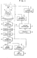
- Such a CT scanner may have a configuration as shown in Fig. 1. (A similar configuration is disclosed in Fig. 1 of U.S. Patent No. 4,293,912 issued on October 6, 1981).
- a main body 1 of the scanner has an X-ray source 2.
- Source 2 radiates a fan beam X-ray FB for each projection within a given spreading range.
- a radiation detector 3 is opposed to X-ray source 2.
- Detector 3 includes a large number of tiny radiation sensors which are arrangea around the radial directions of the spreaded X-ray sector plane.
- Each of the radiation sensors senses, with a certain spatial resolution, the intensity of X-ray from source 2.
- the radiation path definea between source 2 and each of the radiation sensors is called as an X-ray path.
- Each of the radiation sensors delivers an individual signal which indicates the intensity of an X-ray on the corresponding X-ray path.
- Scanner main body 1 is provided with a rotation actuator (not shown).
- X-ray source 2 containing an X-ray tube is mounted on the rotation actuator so that the rotation center of the actuator coincides with the center of a tomography region.
- the actuator serves to effect a single-way rotary scanning of the X-ray.
- the rotary scanning angle is sequentially changed by prescribed degrees.
- An object material 4 to be inspected is placed within tne tomography region.
- An X-ray radiation control, a current and voltage control for the X-ray tube, etc. are pertormed by an x-ray controller 5.
- a rotation control for the rotation actuator is acnieved by a scanner controller 6.
- the operation of controllers 5 and 6 is governea p/ a system controller 7.
- System controller 7 also governs tne whole operation of the CT scanner.
- Various instructions and/or data required by the system controller 7 are obtained from a console 8.
- An operator of the scanner may input
- Respective outputs E3 (analog) from the radiation sensors of defector 3 are supplied to a data collector 9.
- Collector 9 includes an A/D converter. According to a control command 17 from system controller 7, the A/D converter converts the analog outputs E3 into digital X-ray absorption data D9 for each projection.
- Absorption data D9 is supplied to a preprocessor 10. Under the control of system controller 7, data D9 is variously processed through a log-converter, gain corrector, off-set corrector anc so on contained in preprocessor 10.
- Processed data D10 from preprocessor 10 is convoluted by a convolver 11 upon receipt or command 17 from system controller 7.
- Convoluted data Dll from convolver 11 is supplied to a back projector 12.
- data Dll is back-projectea along the projection direction, and reconstruction of a tomographic image of the back-projected data is achieved.
- Reconstructed image data D12 of the back projection is stored in an image memory (RAM) 13.
- Data D13 read-out from memory 13 is supplied to an image converter 14.
- data ot a desired range of CT values contained in data D13 (or data being defined in accordance with the degree or X-ray absorption) is image-converted, so that data D14 representing the desired CT range is displayec with various white levels in a monochrome display screen or a CRT display 15.
- an operator of the scanner manipulates the Key boara of console 8 so that the CT scanner starts to operate.
- system controller 7 instructs the scanner controller 6 to perform the step rotation ot the rotation actuator with a given angle.
- System controller 7 also instructs the X-ray controller 5 to pertorm an intermittent application of a given voltage and current to the X-ray tube for each of the step rotations.
- the period of intermittent voltage and current applications to the X-ray tube for each step rotation is prefixed.
- X-ray source 2 sequentially generates pulsate fan beam X-rays FB.
- Object 4 is located at the rotation center (tomography region) of the rotation actuator, and X-ray source 2 faces the detector 3 through the rotation center. Accordingly, as the rotation actuator rotates, a specific slice of object 4 is subjected to the radiation of fan beam X-rays FB from various directions. Then, X-ray transmittances of respective X-ray paths tor each fan beam X-ray FB are sensed by the radiation sensors of detector 3, and information ot the sensea transmittances is converted to outputs E3.
- the data regarding the converted outputs E3 is collected by data collector 9.
- data collector 9 supplies the collected data D9 to preprocessor 10, so that the collected data D9 is log-converted, gain-corrected, off-set-corrected, etc.
- Preprocessed data D10 from preprocessor 10, which indicates X-ray absorption of respective X-ray paths for each projection, is convoluted in convolver 11.
- Convoluted data Dll from convolver 11 is supplied to back projector 12 in which a back-projecting operation is effected. Then, CT values for the locations ot respective pixels of an image are obtained, and a tomographic image corresponding to the obtained CT values is reconstructed.
- the reconstructed tomographic image is stored in memory 13.
- the gradation or the CT values regaraing a desired region of the stored tomographic image is determined by image converter 14, and the tomographic image with the determined gradation is displayed at CRT display 15.
- the reconstructed tomographic image is displayed on the monochrome display screen with given various white levels.
- tomographic measuring is performed 300 to 600 times for each one rotation or the rotation actuator in scanner main body 1. From this, a long scanning time (5 to 10 seconds or more) is required for each inspection.
- CT scanner of Fig. 1 is used for a relatively simple inspection of industrial products (e.g., a test for merely judging whether or not the inspected product is good), at least a hundred sets or projection data will be required. Accordingly, if such a CT scanner is used for inspecting the inner defects or products to be mass-produced, a smooth, fast flow of mass-produced products in the factory is unobtainable because of the length of time needed for inspection. This is one of the problems to be solved.
- a reference material is often used for a comparable measurement.
- projection data for a water fantom reference sample
- An error due to the characteristic of the CT scanner is detected from the projection data of the water fantom, and values for compensating the error are calculated.
- each of inspection materials is set at the tomography region in place of the water fantom, and the obtained projection data for each inspection material is compensated in accordance with the calculated error-compensating values.
- the compensated projection data is convoluted and back-projected to obtain a reconstructed tomographic image of the inspection material (inspection sample).
- An auxiliary object of the invention is to provide a tomographic testing apparatus in which how a tested inspection sample deviates from a reference sample can be gauged from a tomographic image of the inspection sample.
- a tomographic testing apparatus of the invention employs two data collection modes.
- One of these modes is a reference data collection mode in which a large number of prescribed image data (e.g., Xl, X2, X4, X5, X7, X8 and X10) of a reference sample is obtained.
- the reference sample has no defect.
- the other of these modes is a measurement mode in which a predetermined small number or image data (e.g., Y3, Y6 and Y9) of an inspection sample is obtained.
- the inspection sample may have defective portions.
- the tomographic image of the inspection sample is obtained from the combination (Xl, X2, Y3, X4, X5, Y6, X7, X8, Y9 and X10) of the inspection sample image data (Y3, Y6 and Y9) and the reference sample image data (Xl, X2, X4, X5, X7, X8 and X10) from which specific data (X3, X6 and X9) corresponding to the inspection sample image data (Y3, Y6 and Y9) is deletea.
- the number of data (Y3, Y6 and Y9) to be actually measured is far less than all data (Yl to Y10) of the inspection sample. From this, the testing speed of the apparatus is effectively enhanced.
- the tomographic testing apparatus of the invention detects reference projection data for a reference sample and inspection projection data for an inspection sample. The difference between the reference projection data ana the inspection projection data is reconstructed to obtain a tomographic image of the inspection sample.
- the tomographic image of the difference is characterized by color or by any other suitable means, how the tested inspection sample deviates from the reference sample can be seen from the tomographic image.
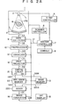
- Fig. 2A is a block diagram showing an X-ray tomographic testing apparatus according to an embodiment of the present invention.
- elements 1 to 15 may have the same configurations as the corresponding elements in Fig. 1.
- the key point of this embodiment is that a means (22) for storing information of a reference sample is provided between data collector 9 and image ! converter 14.
- a switch circuit 21 and reference image memory 22 used as the above storing means are located after the back projector 12. The switching operation of circuit 21 as well as the write/read operation of memories 13 and 22 are controlled by system controller 7.
- the tomographic testing apparatus shown in Fig. 2A employs two operation modes. They are a reference data collection mode and a measurement mode. Which of these modes is selected is determined by an operator's manipulation for console 8.
- switch circuit 21 provides data D21Y corresponding to data D12 in accordance with a command 17 from system controller 7.
- all reconstructed image data of a non-defective reference sample for one rotation i.e., the reconstructed image data of lst to 600th projections
- reference image memory 22 a prescribed major portion of reconstructed image data (e.g., the reconstructed image data of 2nd to 200th projections, 202nd to 400th projections and 402nd to 600th projections) is stored in reference image memory 22.
- the prescribed major portion of reconstructed image data stored in memory 22 (2nd to 200th projections, 202nd to 400th projections and 402nd to 600th projections) can be optionally read out.
- the address of memory 22 for the prescribed major portion of reference sample image data is defined by command I7.
- switch circuit 21 In the measurement mode, in accordance with command I7, switch circuit 21 provides data D21X corresponding to reconstructed image data D12. In this case, a prescribed minor portion of reconstructed image data or a defective inspection sample (e.g., the reconstructed image data of 1st projection, 201st projection and 401st projection) is stored in image memory 13. The address of the prescribed minor portion of inspection sample image data is defined by command I7.
- the angular deviation among these projections is preferably 120 degrees. If four projections (lst, 151st, 301st, 451st) are used in the measurement mode, the angular deviation among these projections is preferably 90 degrees.
- Tomographic image data DT of the inspection sample (lst, 2nd-200th, 201st, 202nd-400th, 401st, and 402nd-600th projections) is obtained by combining the prescribed major portion (2nd-200th, 202nd-400th and 402nd-600th) of the reference sample image data from memory 22 with the prescribed minor portion (lst, 201st and 401st) of the inspection sample image data in memory 13.
- the above combining operation is effected by an adder 220 in such a manner that respective pixels of the reference sample data (D21Y) correspond to those of the inspection sample data (D21X).
- the address for each memory 13, 22 is defined by command 17 from system controller 7, so that specific data (lst, 201st and 401st) corresponding to the inspection sample image data is deleted from the reference sample image data (lst-600th).
- the combined tomographic image data DT is supplied to CRT display 15 via image converter 14.
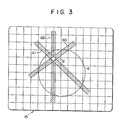
- the tomographic image of. inspection sample 4 is obtained from all of the projections (600 projections) without use . of the tomographic image data of the reference sample, the artifacts indicating the location of the defect cannot be obtained in the displayed image. From this, a small number of projections is suitable for the test of inspection sample 4.
- the geometrical location and/or the size of defect d in the inspection sample can be easily seen from the displayed plural artifacts. This is another important feature obtained from the embodiment of the present invention.
- the Fig. 2A embodiment may be modified such that a plurality of reference image memories (22) are used for storing plural different tomographic image slices of a reference sample. For instance, if 16 slices along the Z axis of a tomographic image on the X-Y plane should be inspected, 16 reference image memories 22-1 to 22-16 are used. These memories 22-1 to 22-16 store 16 different image slices, respectively. According to such a modified embodiment, any desired tomographic image selected from 16 slices of an inspection sample can be optionally and quickly obtained by a key manipulation of console 8.
- three sets of the CT scanners of Fig. 2A may be employed in a manner that the first CT scanner is used for the 1st projection (rotation angle for 0 degrees), the second CT scanner is used for the 201st projection (120 degrees) and the third CT scanner is used for the 401st projection (240 degrees), for example.
- These first to third CT scanners are arranged in series so that an inspection sample continuously and sequentially passes through these CT scanners. In this case, in a measurement mode for test or inspection, there is no need to rotate the source-detector configuration (2, 3 in Fig. 2A), thereby saving time consumption required for the measurement of numerous inspection samples.
- radiation source 2 may utilize a radio isotope.
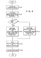
- Fig. 4 is a flow chart showing a typical operational sequence of the CT scanner according to the present invention.
- the mode of operation is designated by an operator of the CT scanner (ST 10).
- the mode is designated as a reference data collection mode.
- the mode is designated as a measurement mode.
- the angles of specific projections for measuring or testing the inspection sample e.g., lst, 201st and 401st projections selected from 600 projections
- the scanner operator is designated by the scanner operator (ST 12).
- the projection angles designated at step ST12 are omitted from measurement, and measurement for the reference sample with respect to the non-omitted projection angles is performed (ST16).
- the measurement mode is designated (NO at ST14)
- measurement for the inspection sample with respect to the designated projection angles is performed (ST18).
- the projection data obtained at step ST18 is combined with or added to the projection data obtained at step ST16, so that projection data for a complete tomographic image is obtained (ST20). ' Then, the combined or added projection data is reconstructed (ST22).
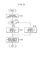
- Fig. 5 is a flow chart showing a part of the control sequence effected by system controller 7 in Fig. 2A.
- the mode of operation is designated by an operator of the CT scanner (ST 30).
- controller 7 instructs the switch circuit 21 to select the contact Y (ST 34).
- controller 7 instructs the switch circuit 21 to select the contact X (ST 36).
- projection data is inputted to the configuration of elements 9 to 12 (ST38), so that measurement (collection of projection data, preprocessing, reconstruction, etc.) is effected.
- the projection data (D21Y) stored at the 2nd-200th, 202nd-400th and 402nd-600th addresses of memory 22 and the projection data (D21X) stored at the lst, 201st and 401st addresses of memory 13 are read out according to command I7 from system controller 7, and these data (D21Y, D21X) from memories 22 and 13 are added together in adder 220.
- memories 13, 22 and adder 220 are controlled by system controller 7 such that respective pixels of the reference sample correspond to those of the inspection sample.
- the added data (D21Y+D21X) thus obtained becomes a complete tomographic image data DT.
- the projection data (D21Y) of the reference sample stored at the 2nd-200th, 202nd-400th and 402nd-600th addresses of memory 22 are transferred via switch circuit 21 to memory 13.
- the transferred data are once stored at the 2nd-200th, 202nd-400th and 402nd-600th addresses of memory 13 in which the projection data (D21X) of the inspection sample are stored at lst, 201st and 401st addresses.
- the projection data (D21X+D21Y or D13) stored at the lst-600th addresses are read out from memory 13 according to command 17.
- This read-out data (D13) corresponds to the complete tomographic image data DT.
- Fig. 6 is a general flow chart showing a basic operation of the CT scanner of the present invention. After the CT scanner operator starts the scanning (ST40), and if the mode is a reference data collection mode (YES at ST42), processing of the reference data collection is performed (ST44). If the mode is a measurement mode (NO at ST42), the measurement is carried out (ST46).
- Fig. 7 shows a subroutine of the reference data collection step ST44 in Fig. 6.
- system controller 7 -detects the rotation angle of the source-detector configuration 2+3 in Fig. 2A (ST52). If the detected angle is not an angle for the measurement, e.g., if the detected angle does not correspond to any of given 1st to 600th projections (NO at ST54), the flow returns to step ST52, and the next rotation angle of the source-detector configuration is detected (ST52). When the detected angle corresponds to one of the given 1st to 600th projections .(YES at ST54), whether or not the detected angle corresponds to one of the reference data collection mode is checked.
- the flow returns to step ST52, and the next rotation angle of the source-detector configuration is detected (ST52).
- the detected angle corresponds to one of the reference data collection mode (YES at ST56)
- YES at ST56 e.g., when the detected angle corresponds to any of 2nd-200th, 202nd-400th and 402nd-600th projections
- an X-ray with a given intensity is temporarily radiated (ST58).
- digital data representing outputs E3 from the radiation detectors is fetched by system controller 7 (ST60).
- the preprocessing, convolution and back projection for the fetched data are effected by elements 10 to 12 in Fig. 2A (ST62-ST66). Then, reconstructed image data is obtained. This obtained data is stored in memory 22 (ST68). If all the reconstructed image data for all of the projection angles (angles for 2nd-200th, 202nd-400th and 402nd-600th projections) in the reference data collection mode is not obtained (NO at ST70), the flow returns to step ST52. When all the reconstructed image data for all of the projection angles in the reference data collection mode is obtained (YES at ST70), an "END" message is displayed at CRT 15 in Fig.2 (ST72) and the subroutine of Fig. 7 is finished.
- Fig. 8 shows a subroutine of the measurement step ST46 in Fig. 6.
- system controller 7 detects the rotation angle of the source-detector configuration 2+3 in Fig. 2A (ST82). If the detected angle is not an angle for the measurement, e.g., if the detected angle does not correspond to any of the given 1st to 600th projections (NO at ST84), the flow returns to step ST82, and the next rotation angle of the source-detector configuration is detected (ST82). When the detected angle corresponds to one of the given 1st to 600th projections (YES at ST84), whether or not the detected angle corresponds to one of the projections for the measurement mode is checked.
- the flow returns to step ST82, and the next rotation angle of the source-detector configuration is detected (ST82).
- ST82 the next rotation angle of the source-detector configuration
- the detected angle corresponds to one of the projections for the measurement mode (YES at ST86)
- YES at ST86 e.g., when the detected angle corresponds to lst, 201st or 401st projection
- an X-ray with a given intensity is temporarily radiated (ST88).
- digital data representing outputs E3 from the radiation detectors is fetched by system controller 7 (ST90).
- the preprocessing, convolution and back projection for the fetched data are effected by elements 10 to 12 in Fig. 2A (ST92-ST96). Then, reconstructed image data is obtained. This obtained data is stored in memory 13 (ST98). If all the reconstructed image data for all of the projection angles (angles for lst, 201st and 401st projections) in the measurement mode is not obtained (NO at ST100), the flow returns to step ST82. When all the reconstructed image data for all of the projection angles in the measurement mode is obtained (YES at ST100), the selected contact (Y) of switch circuit 21 is changed to the contact (X) (ST102).
- Fig. 9 shows a configuration of an X-ray tomographic testing apparatus according to another embodiment of the present invention.
- the reference numeral 21X denotes a scanner main body (which corresponds to element 1 in Fig. 2A).
- the reference numeral 22X denotes an X-ray source (which corresponds to element 2 in Fig. 2A) for generating a fan beam X-ray having a given spreading width.
- the reference numeral 23X denotes a radiation detector (which corresponds to element 3 in Fig. 2A) being opposite X-ray source 22X. Radiation detector 23X is formed with a large number of tiny radiation sensors.
- the radiation sensors are arranged around the spreaded fan beam X-ray and serve to detect, with a certain spatial resolution, the intensity of X-rays from X-ray source 22X.
- X-ray source 22X and radiation detector 23X are mounted on a rotary actuator 24X in a manner that a tomography region 2laX is located at the center between source 22X and detector 23X.
- Rotary actuator 24X serves to effect a one-way step rotation of the sorce-detector configuration (22X+23X) with a given angle.
- the reference numeral 31X denotes an object material (sample to be tested) placed in tomography region 2laX.
- the reference numeral 30X denotes a support member. Support member 30X serves to hold the object material 31X at tomography region 2laX.
- the reference numeral 26X denotes an X-ray controller (which corresponds to element 5 in Fig. 2A). Controller 26X controls the tube current and tube voltage of an X-ray tube in X-ray source 22X.
- the reference numeral 27X denotes a scanner controller (which corresponds to element 6 in Fig. 2A). Controller 27X allows to transmit the rotational power from a drive source M to rotary actuator 24X. The actuation of rotary actuator 24X is controlled by controller 27X.
- the reference numeral 28X denotes a system controller (which corresponds to element 7 in Fig. 2A). Controller 28X controls the whole operation of the tomographic testing apparatus.
- the reference numeral 29X denotes a console (which corresponds to element 8 in Fig. 2A). Console 29X is provided for inputting various instructions, data, etc. Console 29X is manipulated by a system operator when instructions and/or data, etc. are inputted to the testing apparatus.
- the reference numeral 32X denotes a data collector (which corresponds to element 9 in Fig. 2A). Collector 32X receives respective outputs E23X from the radiation sensors in detector 23 X . Data collector 32X delivers X-ray absorption data D32X corresponding to A/D converted radiation sensor outputs E23X.
- the reference numeral 33X denotes a preprocessor (which corresponds to element 10 in Fig. 2A). Preprocessor 33X receives X-ray absorption data D32X for each of the projections collected by data collector 32X. Preprocessor 33X performs prescribed preprocessing such as a gain correction, off-set correction, etc. and delivers preprocessed data D33X corresponding to the inputted X-ray absorption data D32X.
- the reference numeral 34X denotes a data memory.
- Memory 34X stores preprocessed data D33X corresponding to X-ray absorption data D32X of respective projections collected in a reference data collection mode.
- the reference numeral 35X denotes a switch.
- Switch 35X is provided between preprocessor 33X and memory 34X and is used for switching the data transmission of D33X. According to a mode designation by console 29X, switch 35X is controlled by a command I28X from system controller 28, such that the contact A of switch 35X is selected in a reference data collection mode while the contact B thereof is selected in a measurement mode.
- Memory 34X is coupled to the contact A of switch 35X so that it may receive and store the data D35XA (D33X) from preprocessor 33X.
- the reference numeral 36X denotes a subtracter.
- Subtracter 36X receives data D34X from memory 34X and data D35XB (D33X) from preprocessor 33X via the contact B of switch 35X.
- Subtracter 36X delivers data D36X representing a difference (D34X - D35XA) between the data D34X and the data D35XB obtained in the measurement mode.
- subtracter 36X is controlled by system controller 28X, such that the projection of one subtraction input data coincides with the projection of the other subtraction input data, and that the X-ray path of one subtraction input data is identified with the X-ray path of the other subtraction input data.
- the reference numeral 37X denotes a convolver (which corresponds to element 11 in Fig. 2A). Convolver 37X convolutes the preprocessed difference data D36X from subtracter 36X and outputs convoluted data D37X.
- the reference numeral 38X denotes a back projector (which corresponds to element 12 in Fig. 2A). Back projector 38X back-projects the convoluted data D37X along the projection direction and generates reconstructed image data D38X.
- the reference numeral 39X denotes an image memory (which corresponds to element 13 in Fig. 2A) for storing the reconstructed image data D38X.
- the stored contents of memory 39X can be optionally read out as data D39X in accordance with command I28X from system controller 28X.
- the reference numeral 40X denotes an image converter (which corresponds to element 14 in Fig. 2A). Converter 40X serves to convert a desired range of CT values of the data D39X (data with respect to levels of the X-ray absorption) into video data D40X having desired gradations or given colors.
- the reference numeral 42X denotes a CRT display (which corresponds to element 15 in Fig. 2A). CRT 42X displays the tomographic image of data D39X with given gradations and/or given colors.
- the subtraction (D35XB - D34X) is performed after the preprocessing, the subtraction may be performed after the convolution or after the back projection.
- the operation of the testing apparatus in Fig. 9 is initiated by the manipulation of a system operator through console 29X.
- the Fig. 9 embodiment employs two different modes, i.e., a reference data collection mode and a measurement mode. Each of these modes can be designated through console 29X.
- a reference data collection mode data of a reference reconstructed image (i.e., data of the reference sample) is collected.
- a standard model having no inner defect and no size/dimension errors is used for the reference sample, and a routine measuring operation for the reference sample is performed.
- reference sample (object material) 31X is mounted on support 30X so that sample 31X is fixed within tomography region 2laX, and an instruction designating the reference data collection mode is given from console 29X. Then, system controller 28X allows the switch 35X to select the contact A.
- system controller 28X causes the scanner controller 27X to perform a rotation drive control for a given step rotation of rotation actuator 24X. At this time, system controller 28X also causes the X-ray controller 26X to supply, for each of the above step rotations, a given tube current and given tube voltage to X-ray source 22X by a prescribed period.
- pulsate fan beam X-rays FB are sequentially radiated from source 22X. Since object material 31X is placed at the rotation center (tomography region) of actuator 24X and since detector 23X mounted on actuator 24X faces X-ray source 22X mounted thereon through the rotation center, X-ray source 22X is allowed to radiate the fan beam X-rays FB from various directions-toward a given slice of material 31X.
- the radiation transmittance values of respective X-ray paths in the fan beam X-rays F B are sensed by radiation sensors in radiation detector 23X, and the sensed values are converted into electrical signals E23X.
- the above converted signals E23X are collected by data collector 32X in which the collected signals are A/D converted into data D32X.
- A/D converted data D32X is subjected to a log conversion, gain correction, off-set correction and so on for each one projection.
- Preprocessed data D33X from preprocessor 33X (X-ray absorption data of respective X-ray paths for each projection) is supplied via the contact A of switch 35X to memory 34X.
- Memory 34X stores the supplied data (D35XA) for each projection. The above is the operation in the reference data collection mode.
- object material (inspection sample) 31X to be tested is fixed at the given location of support 30X. Since a deviation between the set position of the reference sample and that of the inspection sample disturbs an accurate measurement, the testing apparatus is so arranged that a precise positioning of the.object material is ensured. This may be achieved by providing a referencing plane used for the positioning. After the positioning of inspection sample 31X is completed, if an instruction designating the measurement mode is given from console 29X, system controller 28X causes the switch 35X to select the contact B.
- projection data D34X whose projection is identified with the projection of the above preprocessed projection data D35XB is read out from memory 34X. Then, the read-out projection data D34X is supplied to subtracter 36X. In subtracter 36X, the projection data D34X (D35XA) obtained in the reference data collection mode is subtracted from the projection data D35XB obtained in the measurement mode. The subtracted data D36X from subtracter 36X is supplied to convolver 37X in which a convolution is effected. The convoluted data D37X is back-projected in back projecter 38X, and the back-projected data D38X is stored in memory 39X. Then, the reconstruction of a tomographic image is completed.
- FIG. 10 An example of the reconstructed tomographic image is shown in Fig. 10.
- the solid line A indicates the outline of the reference sample
- the broken line B indicates the outline of the inspection sample
- the slant-lined area C indicates a minus area of CT values
- the dotted area D indicates a plus area of CT values
- another area E indicates zero CT values.
- the abovementioned embodiment since the different portions of the inspection sample with respect to the reference sample are clearly known from the displayed image, an accurate inspection of defect, size and/or dimensions of the tested material is ensured.
- the above embodiment is suitable to inspect a predetermined slice of a sample being formed of a uniform material.
- the difference between a reference sample and an inspection sample may be exaggeratedly displayed.
- the amount (length) of the difference is expanded.
- An exaggerated image can be obtained by modifying a non-exaggerated image in such a manner that the length of the difference along the normal direction of the outline of the reference sample is elongated.
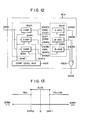
- Fig. 12 shows details of a color converter 40X in Fig. 9.
- Fig. 13 is a graph explaining the operation of color converter 40X.
- Image converter 14 in Fig. 2A or 2B may have the Fig. 12 configuration, of course.
- data D39X from memory 39X is inputted to three digital comparators 402X, 404X and 406X.
- Each of comparators 402X and 404X receives first referece level data Drefl
- each of comparators 404X and 406X receives second referece level data Dref2.
- Reference level data Drefl and Dref2 are obtained from a comparison level generator 410X.
- Comparator 402X generates a comparison result output D402X when D39X > Drefl. This output D402X is supplied to a color generator 422X for generating "yellow” data D422X (D39X > Drefl in Fig. 13). Comparator 404X generates a comparison result output D404X when Drefl > D39X > Dref2. This output D404X is supplied to a color generator 424X for generating "blue" data D424X (Drefl > D39X > Dref2 in Fig. 13). Comparator 406X generates a comparison result output D406X when D39X ⁇ Dref2.
- This output D406X is supplied to a color generator 426X for generating "red" data D426X (D39X ⁇ Dref2 in Fig. 13).
- Data D422X, D424X and D426X are inputted to an OR gate 430X and the ORed output therefrom is supplied as the data D40X to color CRT display 42X.
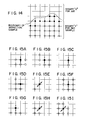
- Fig. 14 shows a distribution of binary-coded "1" data around the boundary (line A in Fig. 11) of a reference sample.
- Figs. 15A to 15J illustrate how the pattern classification of binary-coded "1" data around the boundary of an inspection sample is effected.
- Fig. 16 is a flow chart explaining how emphasizing or exaggerating the difference between a reference sample and a tested inspection sample is achieved.
- the above process for obtaining the elongated length data L is repeated until this processing is completely effected on all binary-coded "1" data at the boundary region of inspection sample 31X. If the processing is not completed, the process for obtaining the data L is sequentially applied to the next unprocessed boundary data at the boundary region of inspection sample 31X (NO at STl18 and ST120). When the above processing is completed, the difference exaggerating operation is finished (YES at ST118). The data L thus obtained is used for displaying the exaggerated tomographic image.
- Fig. 17 shows a configuration of an X-ray tomographic testing apparatus according to another embodiment of the present invention. This embodiment corresponds to the combination of Figs. 2A and 9. According to this embodiment, the tomographic image (indicating defective portions only and containing artifacts) of an inspection sample is obtained from a small number (e.g., three) of the data collection, thereby achieving a speedy test.
- a small number e.g., three
- raw data (D35XA) of a reference sample for all projections are collected, preprocessed and stored in memory 34X.
- raw data (D35XB) of the reference sample for prescribed projections are collected and preprocessed.
- N projection is one of the 2nd-200th, 202nd-400th and 402nd-600th projections).
- the detected difference data (D36X) is reconstructed for said mutually-related projections (2nd-200th, 202nd-400th, 402nd-600th), and the reconstructed difference data (D21Y) is stored in reference image memory 22.
- a third step projection data of an inspection sample for the lst, 201st and 401st projections are collected and preprocessed. Then, the difference (D36X) between the first step preprocessed data (D34X) stored in memory 34X and the third step preprocessed data (D35XB) is detected for each of the mutually-related projections, i.e., the difference between the first step data of an M projection and the third step data of the M projection is detected.
- the detected difference data (D36X) is reconstructed for each of the mutually-related projections (lst, 201st, 401st), and the reconstructed difference data (D21X) is stored in image memory 13.
- the difference data (D21X) stored in memory 13 (lst, 201st and 401st projections) is added by adder 220 to the difference data (D21Y) stored in memory 22 (2nd-200th, 202nd-400th and 402nd-600th projections). Then, a reconstructed tomographic image data DT (for 600 projections) of the difference between the reference sample and the inspection sample is obtained from adder 220.
- the Fig. 17 embodiment has the advantages of both of the embodiments of Figs. 2A and 9.
- Fig. 18 shows another modification of Fig. 2A embodiment.
- back-projected reference image data from back projector 12 is transferred via a signal port X of switch circuit 21 to reference image memory 22, and the transferred data is stored in memory 22.
- the back-projected reference image data stored in memory 22 is set in back projector 12 via a signal port Y of switch circuit 21.
- the back projection for an inspection sample can be effected sequentially on the back-projected reference image data which is set in the back projector for each - projection, the measuring speed for the inspection sample can be effectively enhanced and, in addition, the circuit configuration of the testing apparatus becomes simple.
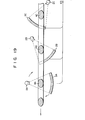
- Fig. 19 shows a practical application of the apparatus of Fig. 2A, 2B, 9, 17 or 18.
- three sets of source-detector configurations 2A+3A, 2B+3B and 2C+3C are employed.
- the first set of source-detector configuration 2A+3A is rotatable around its tomography region through which object materials 4A, 4B, 4C, etc. are passed.
- the first set is used for collecting the reference sample data as well as collecting the inspection sample data of the 1st projection in given 600 projections.
- the second and third sets 2B+3B and 2C+3C are fixed with respect to their tomography regions.
- the second set is used for collecting the inspection sample data of 101st projection
- the third set is used for collecting the inspection sample data of 201st projection. If the projection angle of the first set 2A+3A is defined as 0 degrees, the projection angle of the second set 2B+3B with respect to the first set is 60 degrees and the projection angle of the third set 2C+3C is 120 degrees, as shown in Fig. 19.
- the first set 2A+3A is fixed at 0 degrees.
- An inspection sample to be measured is transferred from the right hand side to the left hand side in the figure.
- inspection sample 4C comes to the tomography region of the third set 2C+3C
- only the third set performs the data collection for the 201st projection of a given slice of the sample.
- the Fig. 19 arrangement is suitable when the testing apparatus is applied to a continuous inspection of mass-produced products on a belt conveyer.
- the present invention may be applied to a first generation CT equipment in which a pencil beam is traversingly and rotatingly scanned to obtain a tomographic image, or applied to a second generation CT equipment in which a narrow width fan beam is traversingly and rotatingly scanned to obtain a tomographic image, or applied to a fourth generation CT equipment in which an object material to be inspected is surrounded by sensor elements and only a radiation source for radiating a fan beam is rotated at the time of scanning.
Landscapes
- Life Sciences & Earth Sciences (AREA)
- Engineering & Computer Science (AREA)
- Health & Medical Sciences (AREA)
- Physics & Mathematics (AREA)
- Medical Informatics (AREA)
- Optics & Photonics (AREA)
- Heart & Thoracic Surgery (AREA)
- High Energy & Nuclear Physics (AREA)
- Theoretical Computer Science (AREA)
- Nuclear Medicine, Radiotherapy & Molecular Imaging (AREA)
- General Physics & Mathematics (AREA)
- Pathology (AREA)
- Radiology & Medical Imaging (AREA)
- Biomedical Technology (AREA)
- Biophysics (AREA)
- Molecular Biology (AREA)
- Surgery (AREA)
- Animal Behavior & Ethology (AREA)
- General Health & Medical Sciences (AREA)
- Public Health (AREA)
- Veterinary Medicine (AREA)
- Analysing Materials By The Use Of Radiation (AREA)
Applications Claiming Priority (4)
| Application Number | Priority Date | Filing Date | Title |
|---|---|---|---|
| JP59027437A JPS60170745A (ja) | 1984-02-16 | 1984-02-16 | 放射線断層検査装置 |
| JP59027436A JPS60190843A (ja) | 1984-02-16 | 1984-02-16 | 放射線断層検査装置 |
| JP27437/84 | 1984-02-16 | ||
| JP27436/84 | 1984-02-16 |
Publications (3)
| Publication Number | Publication Date |
|---|---|
| EP0154429A2 true EP0154429A2 (de) | 1985-09-11 |
| EP0154429A3 EP0154429A3 (en) | 1988-11-23 |
| EP0154429B1 EP0154429B1 (de) | 1993-04-28 |
Family
ID=26365347
Family Applications (1)
| Application Number | Title | Priority Date | Filing Date |
|---|---|---|---|
| EP85300948A Expired - Lifetime EP0154429B1 (de) | 1984-02-16 | 1985-02-13 | Tomographisches Testgerät |
Country Status (3)
| Country | Link |
|---|---|
| US (1) | US4672650A (de) |
| EP (1) | EP0154429B1 (de) |
| DE (1) | DE3587295T2 (de) |
Cited By (7)
| Publication number | Priority date | Publication date | Assignee | Title |
|---|---|---|---|---|
| FR2600442A1 (fr) * | 1986-06-23 | 1987-12-24 | Gen Electric | Procede de reconstruction d'objets a partir de balayages a angle limite dans une tomographie informatisee |
| EP0263080A3 (de) * | 1986-10-01 | 1989-07-26 | Ente per le nuove tecnologie, l'energia e l'ambiente (ENEA) | Verfahren und Vorrichtung zur automatischen radiographischen Echtzeitanalyse von Gegenständen, insbesondere für Schweissnähte in Rohrverschlüssen |
| EP0334762A1 (de) * | 1988-03-25 | 1989-09-27 | General Electric Cgr S.A. | Verfahren und Vorrichtung zur Eichung eines Röntgenstrahl-Abtasters mittels eines nichtkreisförmigen Eichkörpers |
| EP0366528A1 (de) * | 1988-10-28 | 1990-05-02 | General Electric Cgr S.A. | Verfahren und Anordnung zum Eichen eines Röntgen-Abtasters mittels mindestens einem Eichkörper |
| EP0412657A3 (en) * | 1989-08-09 | 1991-05-29 | Picker International, Inc. | Imaging apparatus and methods |
| EP0409219A3 (en) * | 1989-07-21 | 1992-05-13 | Selenia Industrie Elettroniche Associate S.P.A. | Recursive system for image forming by means of a spotlight synthetic aperture radar |
| US5225979A (en) * | 1988-10-28 | 1993-07-06 | General Electric Cgt Sa | Method and system for calibrating an x-ray scanner from the image of at least one calibration standard |
Families Citing this family (9)
| Publication number | Priority date | Publication date | Assignee | Title |
|---|---|---|---|---|
| US4787098A (en) * | 1987-04-10 | 1988-11-22 | Kabushiki Kaisha Toshiba | Method for obtaining calibrated tomographic image data to correct for collimator width differences |
| US4969110A (en) * | 1988-08-01 | 1990-11-06 | General Electric Company | Method of using a priori information in computerized tomography |
| US5228070A (en) * | 1988-10-20 | 1993-07-13 | Picker International, Inc. | Constant image quality CT scanner with variable radiation flux density |
| US5216602A (en) * | 1989-11-06 | 1993-06-01 | The Board Of Trustees Of The University Of Illinois | Color imaging system |
| US6163617A (en) * | 1997-11-26 | 2000-12-19 | Picker International, Inc. | Backprojection with a multi-color rendering engine |
| DE10049822B4 (de) * | 1999-11-03 | 2005-12-22 | Siemens Ag | Verfahren zur Darstellung eines Untersuchungsobjektes unter Verwendung von Schnittbildern |
| JP4588414B2 (ja) * | 2004-10-28 | 2010-12-01 | 株式会社日立製作所 | 内部欠陥検査方法および装置 |
| JP5922892B2 (ja) * | 2011-08-26 | 2016-05-24 | Ntn株式会社 | 転動体の検査方法および転動体の製造方法 |
| KR101413113B1 (ko) * | 2012-11-08 | 2014-08-06 | 주식회사 쓰리디산업영상 | 신관의 결함 여부 판독방법 및 장치 |
Family Cites Families (6)
| Publication number | Priority date | Publication date | Assignee | Title |
|---|---|---|---|---|
| US4149247A (en) * | 1975-12-23 | 1979-04-10 | Varian Associates, Inc. | Tomographic apparatus and method for reconstructing planar slices from non-absorbed and non-scattered radiation |
| NL7710052A (nl) * | 1977-09-14 | 1979-03-16 | Philips Nv | Inrichting voor computer-tomografie. |
| JPS54130891A (en) * | 1978-04-03 | 1979-10-11 | Agency Of Ind Science & Technol | Tomograph using analogue picture memory |
| US4349739A (en) * | 1980-07-28 | 1982-09-14 | American Science And Engineering, Inc. | Micro-calcification detection |
| US4415980A (en) * | 1981-03-02 | 1983-11-15 | Lockheed Missiles & Space Co., Inc. | Automated radiographic inspection system |
| DE3145438A1 (de) * | 1981-11-16 | 1983-05-26 | Siemens AG, 1000 Berlin und 8000 München | Roentgendiagnostikeinrichtung fuer roentgenschichtbilder |
-
1985
- 1985-02-07 US US06/699,089 patent/US4672650A/en not_active Expired - Fee Related
- 1985-02-13 DE DE8585300948T patent/DE3587295T2/de not_active Expired - Fee Related
- 1985-02-13 EP EP85300948A patent/EP0154429B1/de not_active Expired - Lifetime
Cited By (11)
| Publication number | Priority date | Publication date | Assignee | Title |
|---|---|---|---|---|
| FR2600442A1 (fr) * | 1986-06-23 | 1987-12-24 | Gen Electric | Procede de reconstruction d'objets a partir de balayages a angle limite dans une tomographie informatisee |
| EP0263080A3 (de) * | 1986-10-01 | 1989-07-26 | Ente per le nuove tecnologie, l'energia e l'ambiente (ENEA) | Verfahren und Vorrichtung zur automatischen radiographischen Echtzeitanalyse von Gegenständen, insbesondere für Schweissnähte in Rohrverschlüssen |
| EP0334762A1 (de) * | 1988-03-25 | 1989-09-27 | General Electric Cgr S.A. | Verfahren und Vorrichtung zur Eichung eines Röntgenstrahl-Abtasters mittels eines nichtkreisförmigen Eichkörpers |
| FR2629214A1 (fr) * | 1988-03-25 | 1989-09-29 | Thomson Cgr | Procede et systeme d'etalonnage d'un scanner a rayons x en utilisant un seul etalon non circulaire |
| US5095431A (en) * | 1988-03-25 | 1992-03-10 | General Electric Cgr S.A. | Method and system for calibrating an x-ray scanner by employing a single non-circular standard |
| EP0366528A1 (de) * | 1988-10-28 | 1990-05-02 | General Electric Cgr S.A. | Verfahren und Anordnung zum Eichen eines Röntgen-Abtasters mittels mindestens einem Eichkörper |
| FR2638535A1 (fr) * | 1988-10-28 | 1990-05-04 | Gen Electric Cgr | Procede et systeme d'etalonnage d'un scanner a rayons x a partir de l'image d'au moins un etalon |
| US5225979A (en) * | 1988-10-28 | 1993-07-06 | General Electric Cgt Sa | Method and system for calibrating an x-ray scanner from the image of at least one calibration standard |
| EP0409219A3 (en) * | 1989-07-21 | 1992-05-13 | Selenia Industrie Elettroniche Associate S.P.A. | Recursive system for image forming by means of a spotlight synthetic aperture radar |
| EP0412657A3 (en) * | 1989-08-09 | 1991-05-29 | Picker International, Inc. | Imaging apparatus and methods |
| US5159551A (en) * | 1989-08-09 | 1992-10-27 | Picker International, Inc. | Prism architecture for ct scanner image reconstruction |
Also Published As
| Publication number | Publication date |
|---|---|
| EP0154429A3 (en) | 1988-11-23 |
| DE3587295D1 (en) | 1993-06-03 |
| DE3587295T2 (de) | 1993-09-09 |
| EP0154429B1 (de) | 1993-04-28 |
| US4672650A (en) | 1987-06-09 |
Similar Documents
| Publication | Publication Date | Title |
|---|---|---|
| US4672650A (en) | Tomographic testing apparatus | |
| EP0969765B1 (de) | Rekonstruktion von on-line-bildern bei spiral-computertomographen | |
| CA1309514C (en) | Method of using a priori information in computerized tomography | |
| US5218623A (en) | Method and apparatus for specifying slice planes in x-ray computed tomography | |
| US6829379B1 (en) | Methods and apparatus to assist and facilitate vessel analysis | |
| US5606585A (en) | Methods and apparatus for multislice helical image reconstruction in a computer tomography system | |
| US5216601A (en) | Method for fan beam helical scanning using rebinning | |
| JP3682308B2 (ja) | 計算機式断層写真装置及び撮像されるべき物体の像を発生する方法 | |
| EP1192901A1 (de) | Positionsabhängige Röntgenfilterung | |
| TW376313B (en) | Method and apparatus for reconstructing volumetric images in a helical scanning computed tomography system with multiple rows of detectors | |
| JPS6111615B2 (de) | ||
| US4495645A (en) | Computed tomography device | |
| US5208746A (en) | Method for helical scanning with a stationary detector using rebinning and splicing to create detector vertex projection sets | |
| JPH08263638A (ja) | 物体の断層写真像を作成するシステム及び方法 | |
| US4729100A (en) | CT System which convolutes projection data with a frequency varying filter function | |
| US6891963B1 (en) | Image display | |
| US5357429A (en) | Three-dimensional model generation using multiple angle tomographic scan planes | |
| US5611026A (en) | Combining a priori data with partial scan data to project three dimensional imaging of arbitrary objects with computerized tomography | |
| GB2169180A (en) | Ct apparatus and operating method therefor | |
| JP2001128964A (ja) | 画像再構成における重みを前フィルタ処理するための方法及び装置 | |
| US4578753A (en) | Systems and methods for minimizing noncoplanarity artifacts | |
| JPH0319483B2 (de) | ||
| US5539796A (en) | Spiral scanning type x-ray CT apparatus | |
| EP1599838B1 (de) | Verfahren und einrichtung zur volumetrischen bildrekonstruktion | |
| JPH09294739A (ja) | X線ct装置 |
Legal Events
| Date | Code | Title | Description |
|---|---|---|---|
| PUAI | Public reference made under article 153(3) epc to a published international application that has entered the european phase |
Free format text: ORIGINAL CODE: 0009012 |
|
| 17P | Request for examination filed |
Effective date: 19850222 |
|
| AK | Designated contracting states |
Designated state(s): DE FR GB NL |
|
| PUAL | Search report despatched |
Free format text: ORIGINAL CODE: 0009013 |
|
| AK | Designated contracting states |
Kind code of ref document: A3 Designated state(s): DE FR GB NL |
|
| 17Q | First examination report despatched |
Effective date: 19900806 |
|
| GRAA | (expected) grant |
Free format text: ORIGINAL CODE: 0009210 |
|
| AK | Designated contracting states |
Kind code of ref document: B1 Designated state(s): DE FR GB NL |
|
| REF | Corresponds to: |
Ref document number: 3587295 Country of ref document: DE Date of ref document: 19930603 |
|
| ET | Fr: translation filed | ||
| PGFP | Annual fee paid to national office [announced via postgrant information from national office to epo] |
Ref country code: GB Payment date: 19940203 Year of fee payment: 10 |
|
| PGFP | Annual fee paid to national office [announced via postgrant information from national office to epo] |
Ref country code: DE Payment date: 19940209 Year of fee payment: 10 |
|
| PGFP | Annual fee paid to national office [announced via postgrant information from national office to epo] |
Ref country code: FR Payment date: 19940210 Year of fee payment: 10 |
|
| PGFP | Annual fee paid to national office [announced via postgrant information from national office to epo] |
Ref country code: NL Payment date: 19940228 Year of fee payment: 10 |
|
| PLBE | No opposition filed within time limit |
Free format text: ORIGINAL CODE: 0009261 |
|
| STAA | Information on the status of an ep patent application or granted ep patent |
Free format text: STATUS: NO OPPOSITION FILED WITHIN TIME LIMIT |
|
| 26N | No opposition filed | ||
| PG25 | Lapsed in a contracting state [announced via postgrant information from national office to epo] |
Ref country code: GB Effective date: 19950213 |
|
| PG25 | Lapsed in a contracting state [announced via postgrant information from national office to epo] |
Ref country code: NL Effective date: 19950901 |
|
| GBPC | Gb: european patent ceased through non-payment of renewal fee |
Effective date: 19950213 |
|
| PG25 | Lapsed in a contracting state [announced via postgrant information from national office to epo] |
Ref country code: FR Effective date: 19951031 |
|
| NLV4 | Nl: lapsed or anulled due to non-payment of the annual fee |
Effective date: 19950901 |
|
| PG25 | Lapsed in a contracting state [announced via postgrant information from national office to epo] |
Ref country code: DE Effective date: 19951101 |
|
| REG | Reference to a national code |
Ref country code: FR Ref legal event code: ST |