EP0154538A2 - Générateur de parité et de syndrome pour la détection et la correction d'erreur dans les systèmes de transmission numérique - Google Patents
Générateur de parité et de syndrome pour la détection et la correction d'erreur dans les systèmes de transmission numérique Download PDFInfo
- Publication number
- EP0154538A2 EP0154538A2 EP85301464A EP85301464A EP0154538A2 EP 0154538 A2 EP0154538 A2 EP 0154538A2 EP 85301464 A EP85301464 A EP 85301464A EP 85301464 A EP85301464 A EP 85301464A EP 0154538 A2 EP0154538 A2 EP 0154538A2
- Authority
- EP
- European Patent Office
- Prior art keywords
- bit
- bits
- galois field
- parity
- codeword
- Prior art date
- Legal status (The legal status is an assumption and is not a legal conclusion. Google has not performed a legal analysis and makes no representation as to the accuracy of the status listed.)
- Granted
Links
Images


Classifications
-
- H—ELECTRICITY
- H03—ELECTRONIC CIRCUITRY
- H03M—CODING; DECODING; CODE CONVERSION IN GENERAL
- H03M13/00—Coding, decoding or code conversion, for error detection or error correction; Coding theory basic assumptions; Coding bounds; Error probability evaluation methods; Channel models; Simulation or testing of codes
- H03M13/03—Error detection or forward error correction by redundancy in data representation, i.e. code words containing more digits than the source words
- H03M13/05—Error detection or forward error correction by redundancy in data representation, i.e. code words containing more digits than the source words using block codes, i.e. a predetermined number of check bits joined to a predetermined number of information bits
- H03M13/13—Linear codes
- H03M13/15—Cyclic codes, i.e. cyclic shifts of codewords produce other codewords, e.g. codes defined by a generator polynomial, Bose-Chaudhuri-Hocquenghem [BCH] codes
Definitions
- the present invention relates to error detection and correction in digital communication systems and particularly to the generation of parity and syndrome signals for such error correction. Still more particularly the present invention relates to parity and syndrome generation for error correction in multi-channel digital data communication systems using a linear code or a coset of such code, particularly a cyclic code, more particularly a Reed-Solomon code.
- the present invention finds particular application to parity and syndrome generation in error correcting systems of the sort generally described in Berlekamp United States Patent No. 4,162,480, issued July 24, 1979 for Galois Field Computer. Portions of that reference will be repeated herein at some length and the rest is hereby incorporated herein by reference.
- error correcting systems have been provided for data encoded in byte-serial data blocks.
- the present invention is directed to data recorded in byte-parallel, bit-serial form on multi-track instrumentation recorders for high speed recording.
- Information transmitted over a communication channel including a tape recorder, is generally received as a combination of the original information signal and a noise component. Integrity of the information content is almost entirely preserved when ' the signal to noise ratio of the system is large. Accordingly, refinements in design and realization of the appropriate hardware can increase the probability of error-free transmission, theoretically up to the limits imposed by the channel itself. In order to minimize the effect of intrinsic channel limitations, various techniques are employed which ultimately require a compromise between bandwidth and information transfer rate. Various limitations imposed on the channel bandwidth, information rate, and the degree of complexity of receiving and transmitting apparatus contribute to a probable error rate.
- redundancy is a common element among these techniques, mere repetition exacts a heavy penalty in transmission rate. For example, a single repetition reduces the information rate 50 percent and a second repetition (to implement majority logic) reduces the information rate by 66 2/3 percent.
- Other means for assuring message integrity have employed sophisticated coding techniques which permit the detection, location, and correction of errors. Among the desiderata of these coding techniques are high information rate and a capability of correcting multiple errors within any given codeword of transmitted data.
- a codeword of n elements results from encoding operations performed upon the elements of the original data comprising k elements to yield an encoded word ("codeword") of information having k information elements and n-k check elements.
- codeword an encoded word
- the encoded redundancy in the form of n-k check elements is then available during the decoding operations to detect and correct errors in the codeword (including all information and check elements) up to some limit or merely to detect errors up to some larger limit.
- Galois field is a finite field defined by a field generator, the elements of which field may be represented as polynomials in a particular primitive field element, with coefficients in the prime subfield. If the coefficients are presented in serial form with the most significant coefficient first, field elements can alternatively be considered polynomials in z, where z 1 is the delay operator.
- Encoding is done by adding redundant elements to the source data elements in order to make the resulting codeword satisfy prescribed parity checks.
- Each prescribed parity check is formed as a weighted sum of the elements in the codeword.
- the result of each prescribed parity check upon decoding is generally referred to as a syndrome.
- all the syndromes are zero, meaning that the weighted sum of the elements forming each parity check is zero, and the presence of errors is recognized by a non-zero syndrome.
- all the syndromes In the absence of errors for the coset code of a linear code, all the syndromes have some prescribed non-zero value, and the presence of errors is recognized by departures from the prescribed non-zero values.
- Cyclic codes such as Reed-Solomon codes
- the elements of a cyclic codeword can be associated with coefficients of a codeword polynomial.
- the formation of parity checks can be equated with the taking of a remainder upon division of the codeword polynomial by the code generator polynomial for the code.
- the locations of errors and the true value of the erroneous information elements are determined after constructing certain polynomials defined on the Galois field and finding the roots of these polynomials.
- An encoder and decoder are, therefore, required which have the capability of performing Galois field arithmetic.
- the same parity check circuit may be used for encoding and decoding, that is, for generating parity and syndrome bytes.
- the data may be taken in data blocks and associated with coefficients of what may be called a data polynomial.
- the formation of parity checks can be performed identically as in the case of codewords to determine whether or not the data polynomial itself is divisible by the code generator polynomial. If not, the remainder is added to the data polynomial to form the codeword polynomial. Thus the remainder, whether parity or syndrome bytes, may be referred to as a parity check.
- the term "data block bits" refers to bits corresponding to the coefficients of either the data polynomial or the codeword polynomial, as the case may be.
- error correcting codes a particular class of such codes, separately described by Bose, Chaudhuri and Hocquenhem (thus “BCH” codes), are capable of multiple error correction. Special cases of such codes are the Reed-Solomon (RS) codes with respect to which the present invention will be described.
- RS Reed-Solomon
- Berlekamp patent includes a review of the salient aspects of coding theory, applicable to nonbinary BCH codes in general and to RS codes in particular.
- Berlekamp Algebraic Coding Theory (McGraw-Hill, 1968)
- n is the total length in m-bit characters of a word of encoded information
- n 2 m- 1
- t is the error correcting capability of the code.
- Such a codeword is capable of providing sufficient informational redundancy to detect and correct any set of t or fewer independent errors within the codeword of encoded information, or to correct any set of 2t or fewer independent erasures.
- An erasure may be defined as an error of known location within the received codeword.
- a field may be informally defined as a set of elements including the null element, 0, and the unit element, 1, upon which are defined operations of addition, multiplication and division. Addition and multiplication are associative and commutative, and multiplication is distributive with respect to addition. Every element of the field has a unique negative such that the negative of a given element summed with that given element itself yields the null or 0. Further, every nonzero element has a unique reciprocal such that the product of such an element with its reciprocal yields the unit element, 1.
- the elements comprising the field may be considered symbolic representations of binary or ternary or q-ary numbers. The description of the invention will be understood best in terms of a field of characteristic two.
- the general finite field is called the Galois field and is specified by two parameters; a prime p, and an integer m, whereby GF(p m ) describes a unique finite field (the Galois field of order p m ) having p m elements.
- GF(p m ) describes a unique finite field (the Galois field of order p m ) having p m elements.
- all operations between elements comprising the field yield results which are again elements of the field.
- the operation of addition carried out on elements of the finite field GF(2) is defined, modulo 2, according to relations which do not admit of a "carry”.
- a re-encoder also known as a syndrome generator
- the present invention utilizes the properties of an algebraic finite field as stated above, namely, that addition and multiplication are associative and commutative, and multiplication is commutative with respect to addition. This permits each of the coefficients of the data and codeword polynomials to be separately divided to produce remainders, which may then be added together to form the remainders for the division of the entire polynomial.
- the present invention utilizes these same arithmetic properties of the Galois field in respect to data presented byte-parallel, bit-serial.
- the Galois field properties permit each coefficient to be operated upon one bit at a time for the same reasons, the partial parity check for the first bit being operated upon m-l times by z, where z is the inverse of the delay operator s -1 of such Galois field, the next bit m-2 times, on down to the next to last bit.
- These partial parity checks may then be combined to form the m-bit block parity check.
- the data block polynomials are divided by the code generator polynomial by taking the coefficients of the data block polynomials byte-parallel, bit-serial.
- the first bits conventionally the most significant, are used as the dividend in Galois field division by the code generator polynomial to produce a remainder, which may be termed a partial parity check.
- This remainder is multiplied by z
- Successive bits are similarly divided and multiplied to produce respective remainders (partial parity checks) for all bits. These are added to produce the overall remainder as a block parity check, i.e., the parity bytes or syndrome.
- a first circuit responsive to byte-parallel data block bits of the same significance produces a first partial parity check having m-bits in each byte for the bit of such significance in each of the n elements of the respective codeword.
- a second circuit sums in the Galois field over all elements of the codeword the first partial parity checks to form a second partial parity- check having m-bits in each byte.
- a third circuit multiplies the bit content of each of a plurality of m-bit registers by the inverse of the delay operator in the Galois field and produces respective m-bit products and sums the m-bit products with the second partial parity checks to form a third parity check having m bits in each byte.
- a clock provides clock pulses for synchronously clocking the data block bits in the order of significance byte-parallel into the first circuit, clocking the third parity check into the m-bit registers, and clearing the m-bit registers after m bits.
- Another aspect is to provide such generator operating on data blocks in byte-parallel, bit-serial form for the correction of errors in data recorded with a multi-track digital recorder using a Reed-Solomon or other cyclic code.
- the Galois field is GF(2 4 ), that is, GF(16).
- the particular Galois field is that developed by the field qenerator: with a primitive element
- the Galois arithmetic is thus modulo z 4 + z + 1.
- the consequence of this is that there are 15 numbers in the Galois field, in addition to null, 0000, all being powers of a from 0 to 14 that can be stated as third order polynomials in the form F 3 z 3 + F 2 z 2 + F 1 z 1 + F 0 z 0 where the coefficients are binary 0 or 1 as set forth in Table I:
- the present invention provides a system for dividing blocks of incoming data in the form of a 14th order polynomial in x (with the coefficients C 1 and C 0 equal to 0) byte-parallel, bit-serial, by the code generator to obtain a remainder S(x) in the form where S I and S 0 are coefficients in the Galois field in the form S 1 and S 0 are the parity bytes P 1 and P 0 in 4-bit form that, if added to the data block, forms a codeword polynomial exactly divisible by the code generator.
- the codeword may then be recorded byte-parallel, bit-serial as 15 4-bit bytes, with 13 data bytes and 2 parity bytes. (In the specific example for a 14 track recorder, one of the coefficients C 14 to C 2 is 0.)
- the present invention provides a system for dividing the played back codewords by the code generator whereby the remainder S(x) is also in the form and constitutes the syndrome, an error signal that contains information from which errors can be both identified and corrected, within the limits of the Reed-Solomon coding system.
- the present invention is not directed to their correction, which can be performed in the manner as generally explained by Berlekamp.
- Galois field Operation in a Galois field may be simply implemented provided an appropriate Galois field is provided.
- GF(16) with field generator multiplication by z may be effected by the multiplying circuit 8 illustrated in FIGURE 1 utilizing a single exclusive OR-gate 10. That this is so may be shown by common algebra.
- This function is performed by the multiplying circuit 8 of FIGURE 1 wherein input bits F 3 , F 2 , F 1 , F 0 in the order of most significant bit (MSB) to least significant bit (LSB) in an input register 12 are transformed to output bits F 2 , F 1 , (F 3 + F 0 ) and F 3 at an output register 14 using the exclusive-OR gate 10 and wired connections as shown.
- MSB most significant bit
- LSB least significant bit
- multiplication by a which is the same as ⁇ -1 , may be effected by a multiplying circuit 16 as shown in FIGURE 2 utilizing a single exclusive-OR gate 10 with input and output m-bit registers 18 and 20 connected as shown.
- FIGURE 3 A known circuit for implementing parity and syndrome generation for Reed-Solomon encoding and error correction is shown in FIGURE 3. Such circuit operates upon data received (or codewords) byte-serial, bit-parallel. The bytes are clocked serially into a first m-bit register 22 and thence into a second m-bit register 24. The outputs of the second register 24 are clocked back into the first register 22, adding to the input bytes. Feedback from the output to the input of the second register includes the multiplying circuit 16 of FIGURE 2 and provides multiplication by a l4 in the aforementioned Galois field.
- the first register 22 contains the parity byte S 0 (P 0 ) and the second register 24 contains the parity byte S 1 (P 1 ).
- the 15 bytes of the codeword are clocked in to leave the syndrome bytes S 0 , S 1 in the first and second registers 22, 24, respectively.
- Generation of parity and syndrome bytes thus takes n (15) bit cycles.
- FIGURE 4 is illustrated a byte-parallel, bit-serial Reed-Solomon encoder with a parity/syndrome generator 26 according to the present invention for recording byte-parallel data on a multi-track digital tape recorder 28, specifically a 14-track instrumentation recorder in its recording mode.
- 15 channels are illustrated, as that is the capacity of a Reed-Solomon RS (15, 13) code.
- RS Reed-Solomon RS
- one of the channels must contain all nulls in the Galois field.
- Data from a data source 30 are clocked in byte-parallel, bit-serial form into input latches 32 which serve to synchronize the data.
- parity/syndrome generator 26 Such data are then clocked into the parity/syndrome generator 26 and at the same time through to a data delay circuit 34.
- the parity/syndrome generator 26 operates upon a block of incoming data to develop parity bytes P 1 and P o at the parity outputs thereof in m (4) clock cycles.
- the parity signals are applied to respective parallel to serial converters 36 and 38 which convert the respective bytes P 1 and P 0 into bit-serial form.
- Clock pulses synchronize the delay in the data delay circuit 34 with the parity bits from the converters 36 and 38 to place the parity bits in synchronism with the data bits in the respective data blocks.
- the data and parity bits are applied through gate circuits 40 to output latches 42 and clocked synchronously into the recorder 28.
- the recorder 28 is provided with an error correction system according to the principles of Berlekamp.
- FIGURE 5 Such system is illustrated in FIGURE 5.
- the 14 bytes of codeword are clocked byte-parallel, bit-serial into the input latches 32.
- the codewords are clocked into the parity/syndrome register 26 and at the same time through to the data delay circuit 34.
- the parity/syndrome generator 26 operates upon a codeword to develop syndrome bytes S 1 and S 0 which, according to the Reed-Solomon principles as stated by Berlekamp, include information indicating the nature and position of any errors. Assuming no more than one erroneous coefficient per codeword, the errors can be corrected.
- the syndrome bytes are applied to an error correction 256 x 8 PROM 44 programmed according to the Berlekamp principles to provide a 4-bit error value signal applied in parallel to a parallel to serial converter 46 and a 4-bit error location signal applied to a demultiplexer 48.
- the error value signal which indicates which bit or bits are in error, are applied serially to the demultiplexer 48, which thereupon acts to output the respective error value bits in proper synchronism to the particular byte line identified by the error location signal to contain an error.
- the error value bits are added to the bytes (data or parity) by the gate circuits 40 by means of respective exclusive-OR gates 50. As the bits are binary, the errors can only be having bits of the wrong sense.
- Adding an error value 1 bit by carry-less addition with an exclusive-OR gate 50 thus changes the sense and corrects an error.
- the corrected bytes are clocked byte-parallel, bit-serial into the output latches 42.
- the data bytes then pass to a data sink or utilization circuit 52, where the data may be processed.
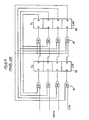
- FIGURE 6 is illustrated a preferred form of parity/syndrome generator 26 of the present invention as applied to the encoder-recorder of FIGURE 4 and the playback decoder-error corrector of FIGURE 5.
- the particular error correcting system was designed for a 14-track instrumentation recorder 28, the system was designed for a (15, 13) Reed-Solomon code, that is one in which the data stream consists of codewords having 15 bytes, of which 2 bytes are parity bytes.
- the codewords will be in the form of the polynomial of 4-bit bytes of the form:
- Every codeword is a multiple of the code generator polynomial, i.e., every codeword can be divided exactly by the code generator with zero remainder.
- the code generator itself is a second order polynomial in the form which in turn is the product of 2 factors where a and b are integers.
- each coefficient of a codeword is a power of a in the Galois field.
- each power of ⁇ may be expressed as the sum of four parts, the most significant being ⁇ 3 or 0, the next ⁇ 2 or 0, the third ⁇ 1 or 0 and the least significant ⁇ 0 or 0.
- the entire codeword may then be divided into four parts, one with binary coefficients of z 3 , a second with binary coefficients of z 2 , a third with binary coefficients of z 1 and a fourth with binary coefficients of-z .
- each of these parts may be divided by the code generator polynomial, and the four resultant remainders may be summed in the Galois field to give the remainder identical to that determined by dividing the entire codeword at once.
- This is the block parity check (parity or syndrome) and permits simplicity of circuitry, as will now be explicated.
- ⁇ 0 x 14 may be divided by the code generator polynomial by polynomial division, leaving a remainder ⁇ 0 x + ⁇ 14 .
- ⁇ 0 is equivalent to
- Each clock period is the time between bits, and the term z -1 is the delay operator in respect to the bits in the Galois field.
- the dividend for the coefficient is multiplied by z 3
- the remainder will be multiplied by the same z 3 . If the most significant bits are applied in parallel to the array 60, the remainder can then be multiplied by z 3 to arrive at the remainder (second partial parity check) that would have resulted had the polynomial with z 3 coefficients been divided by the code generator.
- the circuit of FIGURE 1 may be used for such multiplication, and such circuit is provided by the feedback connections from the 0 outputs of the registers 56, 58 to respective exclusive-OR gates 62 as shown in FIGURE 6, that is, the output of the z 0 place is fed back to the z 1 place; the output of the z 1 place is fed back to the z 2 place; the output of the z 2 place is fed back to the z 3 place; and the output of the z 3 place is fed back to both the z and the z places.
- the most significant bits (z 3 ) may be clocked into the array 60 to provide partial remainder bits (second partial parity check) in the registers 56, 58.
- this partial remainder is multiplied by z and summed with the partial remainder (second partial parity check) from entry of the z 2 bits.
- this combined partial remainder is multiplied by z and summed'with the partial remainder (second partial parity check) from entry of the z 1 bits.
- this combined partial remainder is multiplied by z and summed with the partial remainder (second partial parity check) from entry of the z 0 bits.
- the summation remainder (second partial parity check) in respect to the first bits (z 3 bits) is multiplied by z 3
- all four summation partial remainders as thus successively operated upon are summed by the exclusive-OR gates 62 and entered in the registers 56, 58 to provide the actual remainder S 1 x, S 0 upon division of the input signals (data or codeword) by the code generator polynomial.
- clock signals are provided from conventional clock means. These clock signals are applied at appropriate times to the various registers to assure deskewing of the bytes and proper synchronism of signals.
- the registers 56, 58 are cleared every four clock pulses just prior to entry of the first bits of the parallel bytes. After the four bits have been entered, the remainder (block parity check) is clocked into the parallel to serial converters 36, 38 and thereafter clocked out as the parity check bits at bit rate. Meanwhile the data bits are clocked through the data delay 34 to emerge in synchronism with the parity bits.
- clock pulses are derived from the recorded data and used in a similar fashion to deskew the bytes and apply the bits successively to the various registers, clearing the registers 56, 58 every four bits.
- the syndrome bytes are clocked into the error correction PROM 44, the outputs of which are clocked into the parallel to serial converter 46 and the demultiplexer 48 in proper synchronism.
- the codewords are clocked through the data delay 34 so that its output bytes are synchronized with the error correction.
- Reed-Solomon code i.e., RS (15, 13)
- modification may be made therein for other Reed-Solomon codes.
- Other Galois fields may be used and other primitives.
- Other codewords may be used. Any linear code based upon elements of GF(2 m ) may be used. Any coset of a linear code based upon elements of GF(2 m ) may be used.
- the data blocks may have a different number of bytes per codeword, and there may be a different number of bits per byte.
- a significant feature is that all bytes are- applied in parallel, bit-serial, to a circuit acting in the Galois field to divide each single bit codeword by the code generator, and to means acting upon each clock pulse to multiply the resulting remainder in the Galois field by z, the inverse of delay operator, until all bits of a data block have been clocked in, at the same time adding the remainders from the division of successive bit codewords.
- the circuit shown in FIGURE 5 was developed to serve the conventional order of bit processing wherein the most significant bits are entered first, followed by the other bits in order of significance. Should the bits be entered in the reverse order, the array 60 may be set up for division of the most significant bit and the feedback connections set to multiply by z -1 , as by using the circuit of FIGURE 2. This is the same as operating in the Galois field defined by the reciprocal field generator polynomial and multiplying by the inverse of the delay operator of such field.
- Coset codes are conventionally used in recording.
- One use is in synchronization, wherein fixed patterns may be added to the input data block to prevent the occurrence of particular bit streams, such as all 0's.
Landscapes
- Physics & Mathematics (AREA)
- Algebra (AREA)
- General Physics & Mathematics (AREA)
- Mathematical Physics (AREA)
- Pure & Applied Mathematics (AREA)
- Probability & Statistics with Applications (AREA)
- Engineering & Computer Science (AREA)
- Theoretical Computer Science (AREA)
- Error Detection And Correction (AREA)
- Detection And Correction Of Errors (AREA)
Applications Claiming Priority (2)
| Application Number | Priority Date | Filing Date | Title |
|---|---|---|---|
| US586526 | 1984-03-05 | ||
| US06/586,526 US4555784A (en) | 1984-03-05 | 1984-03-05 | Parity and syndrome generation for error detection and correction in digital communication systems |
Publications (3)
| Publication Number | Publication Date |
|---|---|
| EP0154538A2 true EP0154538A2 (fr) | 1985-09-11 |
| EP0154538A3 EP0154538A3 (en) | 1987-08-26 |
| EP0154538B1 EP0154538B1 (fr) | 1991-08-14 |
Family
ID=24346103
Family Applications (1)
| Application Number | Title | Priority Date | Filing Date |
|---|---|---|---|
| EP85301464A Expired - Lifetime EP0154538B1 (fr) | 1984-03-05 | 1985-03-04 | Générateur de parité et de syndrome pour la détection et la correction d'erreur dans les systèmes de transmission numérique |
Country Status (4)
| Country | Link |
|---|---|
| US (1) | US4555784A (fr) |
| EP (1) | EP0154538B1 (fr) |
| JP (1) | JPS60213131A (fr) |
| DE (1) | DE3583753D1 (fr) |
Cited By (9)
| Publication number | Priority date | Publication date | Assignee | Title |
|---|---|---|---|---|
| WO1992003879A1 (fr) * | 1990-08-15 | 1992-03-05 | Televerket | Procede de recuperation de bits perdus lors de la transmission numerique |
| WO1994010798A1 (fr) * | 1992-11-05 | 1994-05-11 | Ampex Systems Corporation | Circuit de detection et de correction d'erreurs de signaux de synchronisation video |
| EP0629052A4 (fr) * | 1992-12-25 | 1995-11-29 | Sony Corp | Procede et circuit de correction d'erreurs. |
| US5499251A (en) * | 1990-08-15 | 1996-03-12 | Televerket | Method of recovering lost bits in a digital transmission |
| EP0687072A3 (fr) * | 1994-06-10 | 1996-10-02 | Hughes Aircraft Co | Appareil et méthode de décodage accéléré de blocs linéaires pour des récepteurs de communication cellulaire digitale et pour d'autres systèmes |
| EP0790710A3 (fr) * | 1995-12-22 | 1997-09-17 | ANSALDO TRASPORTI S.p.A. | Méthode pour la validation rapide et la codification pour code cyclique |
| US7314341B2 (en) | 2003-01-10 | 2008-01-01 | Liconic Ag | Automatic storage device and climate controlled cabinet with such a device |
| CN111788559A (zh) * | 2018-03-05 | 2020-10-16 | 阿里巴巴集团控股有限公司 | 通过伽罗瓦域维折叠支持具有唯一纠错码的多页长度 |
| CN119415313A (zh) * | 2024-09-29 | 2025-02-11 | 山东云海国创云计算装备产业创新中心有限公司 | 分区命名空间固态硬盘的数据备份方法、装置及电子设备 |
Families Citing this family (30)
| Publication number | Priority date | Publication date | Assignee | Title |
|---|---|---|---|---|
| US4672612A (en) * | 1984-03-30 | 1987-06-09 | Oki Electric | Error correction system in a teletext system |
| US4675868A (en) * | 1984-03-30 | 1987-06-23 | Oki Electric Industry Co., Ltd. | Error correction system for difference set cyclic code in a teletext system |
| JPH0664862B2 (ja) * | 1984-09-19 | 1994-08-22 | 株式会社日立製作所 | デイジタル画像記録再生装置 |
| JPS6214305A (ja) * | 1985-07-12 | 1987-01-22 | Fujitsu Ltd | 磁気テ−プ装置のライトエラ−処理方法 |
| US4914576A (en) * | 1986-12-18 | 1990-04-03 | Bull Hn Information Systems Inc. | Apparatus and method of loading a control store memory of a central subsystem |
| EP0329789B1 (fr) * | 1987-06-30 | 1995-02-08 | Matsushita Electric Industrial Co., Ltd. | Unite arithmetique a champ de galois |
| EP0473102B1 (fr) * | 1990-08-29 | 1995-11-22 | Honeywell Inc. | Système de transmission de données comprenant des moyens de calcul de somme de vérification |
| US5428629A (en) * | 1990-11-01 | 1995-06-27 | Motorola, Inc. | Error check code recomputation method time independent of message length |
| JP2824474B2 (ja) * | 1992-02-17 | 1998-11-11 | 三菱電機株式会社 | 誤り訂正方式及びこの誤り訂正方式を用いた復号器 |
| KR950010768B1 (ko) * | 1993-10-20 | 1995-09-22 | 주식회사 Lg전자 | 에러 정정 코드 복호 장치 및 그 방법 |
| US6308295B1 (en) | 1996-10-08 | 2001-10-23 | Arizona Board Of Regents | Parallel spectral reed-solomon encoder and decoder |
| JPH11136136A (ja) * | 1997-10-29 | 1999-05-21 | Nec Corp | リードソロモン符号化装置及び方法 |
| US6574776B1 (en) * | 1999-04-09 | 2003-06-03 | Oak Technology, Inc. | Simultaneous processing for error detection and P-parity ECC encoding |
| US6141786A (en) * | 1998-06-04 | 2000-10-31 | Intenational Business Machines Corporation | Method and apparatus for performing arithmetic operations on Galois fields and their extensions |
| US7028248B2 (en) * | 2001-02-28 | 2006-04-11 | International Business Machines Corporation | Multi-cycle symbol level error correction and memory system |
| US20090199075A1 (en) * | 2002-11-25 | 2009-08-06 | Victor Demjanenko | Array form reed-solomon implementation as an instruction set extension |
| US8650470B2 (en) | 2003-03-20 | 2014-02-11 | Arm Limited | Error recovery within integrated circuit |
| KR100617769B1 (ko) * | 2004-03-24 | 2006-08-28 | 삼성전자주식회사 | 채널 부호화 장치 및 방법 |
| GB2421599B8 (en) * | 2004-12-22 | 2008-10-22 | Martin Tomlinson | A system for the correction of missing or deleted symbols |
| JP4864395B2 (ja) * | 2005-09-13 | 2012-02-01 | 株式会社東芝 | 半導体記憶装置 |
| JP4619931B2 (ja) * | 2005-11-22 | 2011-01-26 | 株式会社東芝 | 復号装置、記憶装置および復号方法 |
| US7607068B2 (en) * | 2006-08-31 | 2009-10-20 | Intel Corporation | Apparatus and method for generating a Galois-field syndrome |
| US7738657B2 (en) * | 2006-08-31 | 2010-06-15 | Intel Corporation | System and method for multi-precision division |
| US7797612B2 (en) * | 2006-12-29 | 2010-09-14 | Intel Corporation | Storage accelerator |
| US20110172975A1 (en) * | 2009-08-19 | 2011-07-14 | University Of Sao Paulo | Generation and reproduction of dna sequences and analysis of polymorphisms and mutations by using error-correcting codes |
| US8924814B2 (en) | 2012-08-28 | 2014-12-30 | Seagate Technology Llc | Write management using partial parity codes |
| WO2013038464A1 (fr) * | 2011-09-16 | 2013-03-21 | Hitachi, Ltd. | Codage en plusieurs étages et décodage de codes bch pour mémoires flash |
| US8788915B2 (en) | 2012-03-05 | 2014-07-22 | Micron Technology, Inc. | Apparatuses and methods for encoding using error protection codes |
| US9811418B2 (en) | 2015-10-26 | 2017-11-07 | Sandisk Technologies Llc | Syndrome-based codeword decoding |
| US10958530B1 (en) | 2019-08-29 | 2021-03-23 | Jump Algorithms, Llc | Networking systems and methods using multipath asynchronous Galois information coding |
Family Cites Families (21)
| Publication number | Priority date | Publication date | Assignee | Title |
|---|---|---|---|---|
| DE1080328B (de) * | 1955-04-01 | 1960-04-21 | Int Standard Electric Corp | Pruefeinrichtung fuer Binaerspeicher |
| US3137788A (en) * | 1960-11-04 | 1964-06-16 | Emi Ltd | Error checking system using residue redundancy |
| US3227865A (en) * | 1962-06-29 | 1966-01-04 | Ibm | Residue checking system |
| US3349370A (en) * | 1964-03-10 | 1967-10-24 | Gen Precision Systems Inc | Write amplifier circuit |
| US3439331A (en) * | 1965-06-16 | 1969-04-15 | Ibm | Error detection and correction apparatus |
| US3495215A (en) * | 1965-12-30 | 1970-02-10 | Us Navy | Decoding system |
| GB1184498A (en) * | 1967-10-03 | 1970-03-18 | Nat Res Dev | Calculating Apparatus. |
| US3745528A (en) * | 1971-12-27 | 1973-07-10 | Ibm | Error correction for two tracks in a multitrack system |
| US3781829A (en) * | 1972-06-16 | 1973-12-25 | Ibm | Test pattern generator |
| US3794819A (en) * | 1972-07-03 | 1974-02-26 | Advanced Memory Syst Inc | Error correction method and apparatus |
| JPS5119922A (fr) * | 1974-08-10 | 1976-02-17 | Sharp Kk | |
| US4162480A (en) * | 1977-01-28 | 1979-07-24 | Cyclotomics, Inc. | Galois field computer |
| US4281355A (en) * | 1978-02-01 | 1981-07-28 | Matsushita Electric Industrial Co., Ltd. | Digital audio signal recorder |
| NL7804673A (nl) * | 1978-05-02 | 1979-11-06 | Philips Nv | Systeem voor het overdragen van binaire informatie over een aantal kanalen. |
| US4202018A (en) * | 1978-09-27 | 1980-05-06 | Soundstream, Inc. | Apparatus and method for providing error recognition and correction of recorded digital information |
| US4211997A (en) * | 1978-11-03 | 1980-07-08 | Ampex Corporation | Method and apparatus employing an improved format for recording and reproducing digital audio |
| US4377862A (en) * | 1978-12-06 | 1983-03-22 | The Boeing Company | Method of error control in asynchronous communications |
| JPS55102949A (en) * | 1979-01-31 | 1980-08-06 | Toshiba Corp | Data correction circuit |
| US4357702A (en) * | 1980-11-28 | 1982-11-02 | C.N.R., Inc. | Error correcting apparatus |
| JPS58213543A (ja) * | 1982-06-04 | 1983-12-12 | Mitsubishi Electric Corp | 符号誤り修正方式 |
| US4527269A (en) * | 1983-02-08 | 1985-07-02 | Ampex Corporation | Encoder verifier |
-
1984
- 1984-03-05 US US06/586,526 patent/US4555784A/en not_active Expired - Lifetime
-
1985
- 1985-03-04 JP JP60042535A patent/JPS60213131A/ja active Pending
- 1985-03-04 EP EP85301464A patent/EP0154538B1/fr not_active Expired - Lifetime
- 1985-03-04 DE DE8585301464T patent/DE3583753D1/de not_active Expired - Lifetime
Cited By (11)
| Publication number | Priority date | Publication date | Assignee | Title |
|---|---|---|---|---|
| WO1992003879A1 (fr) * | 1990-08-15 | 1992-03-05 | Televerket | Procede de recuperation de bits perdus lors de la transmission numerique |
| US5499251A (en) * | 1990-08-15 | 1996-03-12 | Televerket | Method of recovering lost bits in a digital transmission |
| WO1994010798A1 (fr) * | 1992-11-05 | 1994-05-11 | Ampex Systems Corporation | Circuit de detection et de correction d'erreurs de signaux de synchronisation video |
| EP0629052A4 (fr) * | 1992-12-25 | 1995-11-29 | Sony Corp | Procede et circuit de correction d'erreurs. |
| US5541940A (en) * | 1992-12-25 | 1996-07-30 | Sony Corporation | Error correction method and error correction circuit |
| EP0687072A3 (fr) * | 1994-06-10 | 1996-10-02 | Hughes Aircraft Co | Appareil et méthode de décodage accéléré de blocs linéaires pour des récepteurs de communication cellulaire digitale et pour d'autres systèmes |
| US5677919A (en) * | 1994-06-10 | 1997-10-14 | Hughes Electronics | Faster linear block decoding apparatus and method for receivers in digital cellular communication and other systems |
| EP0790710A3 (fr) * | 1995-12-22 | 1997-09-17 | ANSALDO TRASPORTI S.p.A. | Méthode pour la validation rapide et la codification pour code cyclique |
| US7314341B2 (en) | 2003-01-10 | 2008-01-01 | Liconic Ag | Automatic storage device and climate controlled cabinet with such a device |
| CN111788559A (zh) * | 2018-03-05 | 2020-10-16 | 阿里巴巴集团控股有限公司 | 通过伽罗瓦域维折叠支持具有唯一纠错码的多页长度 |
| CN119415313A (zh) * | 2024-09-29 | 2025-02-11 | 山东云海国创云计算装备产业创新中心有限公司 | 分区命名空间固态硬盘的数据备份方法、装置及电子设备 |
Also Published As
| Publication number | Publication date |
|---|---|
| EP0154538A3 (en) | 1987-08-26 |
| US4555784A (en) | 1985-11-26 |
| DE3583753D1 (de) | 1991-09-19 |
| EP0154538B1 (fr) | 1991-08-14 |
| JPS60213131A (ja) | 1985-10-25 |
Similar Documents
| Publication | Publication Date | Title |
|---|---|---|
| US4555784A (en) | Parity and syndrome generation for error detection and correction in digital communication systems | |
| US4782490A (en) | Method and a system for multiple error detection and correction | |
| US4504948A (en) | Syndrome processing unit for multibyte error correcting systems | |
| US4958349A (en) | High data rate BCH decoder | |
| US5343481A (en) | BCH error-location polynomial decoder | |
| US5699368A (en) | Error-correcting encoder, error-correcting decoder, and data transmitting system with error-correcting codes | |
| US4486882A (en) | System for transmitting binary data via a plurality of channels by means of a convolutional code | |
| US5440570A (en) | Real-time binary BCH decoder | |
| US5872799A (en) | Global parity symbol for interleaved reed-solomon coded data | |
| Leung-Yan-Cheong et al. | Concerning a bound on undetected error probability (Corresp.) | |
| EP0233075B1 (fr) | Méthode et appareil pour générer des bytes de contrôle pour la détection d'erreurs dans des blocs de données | |
| US5912905A (en) | Error-correcting encoder, error-correcting decoder and data transmitting system with error-correcting codes | |
| EP0061345B1 (fr) | Circuit de traitement opérant sur des mots de données numériques qui sont des éléments d'un corps de Galois | |
| US4691319A (en) | Method and system for detecting a predetermined number of unidirectional errors | |
| US4527269A (en) | Encoder verifier | |
| US3983536A (en) | Data signal handling arrangements | |
| CA1213673A (fr) | Correction d'erreurs en rafale au moyen de codes de bloc cycliques | |
| US7458007B2 (en) | Error correction structures and methods | |
| EP1102406A2 (fr) | Appareil et méthode pour décoder des données digitales | |
| EP0262944B1 (fr) | Appareil de correction d'erreurs | |
| US7539918B2 (en) | System and method for generating cyclic codes for error control in digital communications | |
| US4644543A (en) | Forward error correction hardware for a data adaptor | |
| EP0329775B1 (fr) | Circuit et methode de codage, decodage et de correction d'erreur reed-solomon a grande largeur de bande | |
| US4298981A (en) | Decoding shortened cyclic block codes | |
| EP0341851A2 (fr) | Méthode et appareil de codage entrelacé |
Legal Events
| Date | Code | Title | Description |
|---|---|---|---|
| PUAI | Public reference made under article 153(3) epc to a published international application that has entered the european phase |
Free format text: ORIGINAL CODE: 0009012 |
|
| AK | Designated contracting states |
Designated state(s): CH DE FR GB LI NL SE |
|
| PUAL | Search report despatched |
Free format text: ORIGINAL CODE: 0009013 |
|
| AK | Designated contracting states |
Kind code of ref document: A3 Designated state(s): CH DE FR GB LI NL SE |
|
| 17P | Request for examination filed |
Effective date: 19871212 |
|
| 17Q | First examination report despatched |
Effective date: 19890714 |
|
| GRAA | (expected) grant |
Free format text: ORIGINAL CODE: 0009210 |
|
| AK | Designated contracting states |
Kind code of ref document: B1 Designated state(s): DE FR GB NL |
|
| REF | Corresponds to: |
Ref document number: 3583753 Country of ref document: DE Date of ref document: 19910919 |
|
| ET | Fr: translation filed | ||
| PLBE | No opposition filed within time limit |
Free format text: ORIGINAL CODE: 0009261 |
|
| STAA | Information on the status of an ep patent application or granted ep patent |
Free format text: STATUS: NO OPPOSITION FILED WITHIN TIME LIMIT |
|
| 26N | No opposition filed | ||
| REG | Reference to a national code |
Ref country code: GB Ref legal event code: 732E |
|
| PGFP | Annual fee paid to national office [announced via postgrant information from national office to epo] |
Ref country code: GB Payment date: 19940222 Year of fee payment: 10 |
|
| PGFP | Annual fee paid to national office [announced via postgrant information from national office to epo] |
Ref country code: FR Payment date: 19940310 Year of fee payment: 10 Ref country code: DE Payment date: 19940310 Year of fee payment: 10 |
|
| PGFP | Annual fee paid to national office [announced via postgrant information from national office to epo] |
Ref country code: NL Payment date: 19940331 Year of fee payment: 10 |
|
| NLS | Nl: assignments of ep-patents |
Owner name: AMPEX SYSTEMS CORPORATION TE REDWOOD CITY, CALIFOR |
|
| PG25 | Lapsed in a contracting state [announced via postgrant information from national office to epo] |
Ref country code: GB Effective date: 19950304 |
|
| PG25 | Lapsed in a contracting state [announced via postgrant information from national office to epo] |
Ref country code: NL Effective date: 19951001 |
|
| GBPC | Gb: european patent ceased through non-payment of renewal fee |
Effective date: 19950304 |
|
| PG25 | Lapsed in a contracting state [announced via postgrant information from national office to epo] |
Ref country code: FR Free format text: LAPSE BECAUSE OF NON-PAYMENT OF DUE FEES Effective date: 19951130 |
|
| NLV4 | Nl: lapsed or anulled due to non-payment of the annual fee |
Effective date: 19951001 |
|
| PG25 | Lapsed in a contracting state [announced via postgrant information from national office to epo] |
Ref country code: DE Effective date: 19951201 |
|
| REG | Reference to a national code |
Ref country code: FR Ref legal event code: ST |