EP0154546A2 - Roue à pivot - Google Patents
Roue à pivot Download PDFInfo
- Publication number
- EP0154546A2 EP0154546A2 EP85301498A EP85301498A EP0154546A2 EP 0154546 A2 EP0154546 A2 EP 0154546A2 EP 85301498 A EP85301498 A EP 85301498A EP 85301498 A EP85301498 A EP 85301498A EP 0154546 A2 EP0154546 A2 EP 0154546A2
- Authority
- EP
- European Patent Office
- Prior art keywords
- wheel
- bushing
- axle
- bore
- castor
- Prior art date
- Legal status (The legal status is an assumption and is not a legal conclusion. Google has not performed a legal analysis and makes no representation as to the accuracy of the status listed.)
- Withdrawn
Links
Images
Classifications
-
- B—PERFORMING OPERATIONS; TRANSPORTING
- B60—VEHICLES IN GENERAL
- B60B—VEHICLE WHEELS; CASTORS; AXLES FOR WHEELS OR CASTORS; INCREASING WHEEL ADHESION
- B60B33/00—Castors in general ; Anti-clogging castors
- B60B33/0036—Castors in general ; Anti-clogging castors characterised by type of wheels
- B60B33/0042—Double or twin wheels
-
- B—PERFORMING OPERATIONS; TRANSPORTING
- B60—VEHICLES IN GENERAL
- B60B—VEHICLE WHEELS; CASTORS; AXLES FOR WHEELS OR CASTORS; INCREASING WHEEL ADHESION
- B60B33/00—Castors in general ; Anti-clogging castors
- B60B33/0028—Construction of wheels; methods of assembling on axle
-
- Y—GENERAL TAGGING OF NEW TECHNOLOGICAL DEVELOPMENTS; GENERAL TAGGING OF CROSS-SECTIONAL TECHNOLOGIES SPANNING OVER SEVERAL SECTIONS OF THE IPC; TECHNICAL SUBJECTS COVERED BY FORMER USPC CROSS-REFERENCE ART COLLECTIONS [XRACs] AND DIGESTS
- Y10—TECHNICAL SUBJECTS COVERED BY FORMER USPC
- Y10S—TECHNICAL SUBJECTS COVERED BY FORMER USPC CROSS-REFERENCE ART COLLECTIONS [XRACs] AND DIGESTS
- Y10S16/00—Miscellaneous hardware, e.g. bushing, carpet fastener, caster, door closer, panel hanger, attachable or adjunct handle, hinge, window sash balance
- Y10S16/42—Miscellaneous methods
-
- Y—GENERAL TAGGING OF NEW TECHNOLOGICAL DEVELOPMENTS; GENERAL TAGGING OF CROSS-SECTIONAL TECHNOLOGIES SPANNING OVER SEVERAL SECTIONS OF THE IPC; TECHNICAL SUBJECTS COVERED BY FORMER USPC CROSS-REFERENCE ART COLLECTIONS [XRACs] AND DIGESTS
- Y10—TECHNICAL SUBJECTS COVERED BY FORMER USPC
- Y10T—TECHNICAL SUBJECTS COVERED BY FORMER US CLASSIFICATION
- Y10T403/00—Joints and connections
- Y10T403/60—Biased catch or latch
Definitions
- the invention relates to a wheeled castor, and particularly though not exclusively to a dual-wheeled castor.
- Lightweight dual wheeled castors have found can- siderable commercial acceptance over the last decade for supporting office furniture and equipment as well as some residential furniture. As a result of this acceptance, the manufacture of lightweight dual wheel castors has been extremely competitive and engineering efforts to reduce the cost of the castors while maintaining adequate strength, reliability and durability have been keen.
- the castors include a central arcuate horn member that carries a vertically arranged pintle that fits within a socket plate fixed to the underside of the furniture or equipment to be supported in a manner so that the castor has swiveling motion.
- This horn carries a one or two-piece axle and usually the axle is non-rotatably fixed to the horn.
- Each of the wheels frequently has an integral hub with a central bore that is received on the projecting ends of the axle.
- U.S. Design Patent No. 220,938 Another method of attaching wheels to this type of dual wheel castor is shown in U.S. Design Patent No. 220,938 and this uses a U-shaped metal spring clip carried by the underside of the horn that has legs that fit over radial flanges on the inner surface of the wheels around the wheel hubs.
- the flanges on the hub significantly increase the cost of the wheel because they cannot be moulded integrally with the wheel, and the spring clip frequently becomes dislodged from the lower side of the horn permitting the wheels to freely slide off the axle.
- Another method of attaching dual wheel castor wheels is to form an axle-receiving bore entirely through the wheel and attach a snap ring over an end of the axle projecting outwardly from each wheel.
- the axle and snap ring are visible from the outside of the wheel and therefore require a hub cap or other decorative element to conceal the axle ends, which significantly increases the cost of the castor in this competitive market.
- a wheeled castor includes a rotary wheel and a stationary wheel support, the wheel being supported on the wheel support by a shaft and bore connection which includes locking means to restrain or prevent separation of the wheel and wheel support after their assembly, characterised in that the shaft and bore connection includes a shaft portion (14) on one of the wheel and the wheel support, part of the locking means being formed by a locking recess (24,25) in the shaft position, the bore (53,55) receiving a bushing (19,20) which has at least one resilient locking portion (46,47,48) forming another part of the locking means, and which extends radially inwardly of the bore, assembly being achieved by relative axial movement of the wheel and wheel support to engage the shaft portion in the bore such that the resilient locking portion or portions (46,47,48) is/are received in the locking recess (24,25) axially to lock the wheel and wheel support.
- the resilient portion is such that it is moved outward by the axle and then springs back into the locking
- the present castor may, specifically, include an arcuate central horn having a vertical pintle boss constructed of a one-piece plastic moulding with a metal transverse axle insert-moulded therein.
- the axle may also have a central splined portion around which the horn is moulded to prevent rotation of the axle with respect to the horn and its ends may project laterally from the horn, to allow a wheel to be mounted on each end.
- a further preferable feature is that the bushing extends only part way through the wheel bore and the wheel is partly supported for rotation on a bearing surface on the bushing and partly on a bearing surface on the wheel, the two bearing surfaces being axially supported.
- a method of manufacture of a wheeled castor comprises a dual wheeled castor (10) characterised by a mounting member (11) from which projects a pair of axle portions (14) each having a locking recess (24,25) adjacent its end, each end of the axle rotatably carrying a bushing (19,20) having at least one resilient locking portion (46,47,48) which is received into the locking recess to lock the bushing axially to the axle and a wheel (15,16) having an axially-extending bore (53,55), the bushing being secured in the bore.
- the wheels travel preferably down a line with the inside hub of the wheel facing upwardly and the bushings are dropped into the stepped wheel bores with the energy director rims engaging the wheel hubs.
- the bushing flanges are preferably then sonic- welded to the hub with a suitable ultrasonic welding tool rendering the bushing and the hub essentially a one-piece unit.
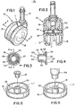
- FIGs 1 and 2 illustrate an assembled dual-wheel castor 10 according to the present invention. It includes an arcuate central horn 11 carrying a vertical swivel pintle 12, and a horizontally extending axle 14 upon opposite ends of which wheels 15 and 16 are rotatably mounted. The wheels 15 and 16 are axially locked on the axle 14 by a pair of identical bushings 19 and 20, the form of which is shown, for example, in Figures 3, 4 and 5.
- the axle 14 is insert-moulded in the horn 11 and includes an enlarged, central axially-knurled portion 22 that prevents both rotational and axial movement of the axle with respect to horn 11.
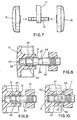
- the ends of the axle 14 projecting from the horn 11 are of uniform diameter, except for recesses 24 and 25 one on each axle end and which are identical to each other. As seen more clearly in Figure 8 the recesses each include an annular radial shoulder 27 and an inwardly converging frusto-conical surface 29.
- the recesses 24 and 25 separate the axle ends into a first cylindrical outer, bearing surface 31 , and a second cylindrical, inner, bearing surface 32, both of the same diameter.
- the distal ends of the axle each have a short chamfer as indicated at 35.
- the bushings 19 and 20 are identical and, as seen in Figs. 3 and 4, are generally annular in configuration with an intermediate annular portion 38, from one end of which an annular radially extending flange 39 extends. The other end forms a spheroidal portion 41 , with axially extending slots 42, 43 and 44 therein, that define three identical resilient spring fingers 46, 47 and 48.
- the relaxed inner diameter between the free ends of the spring fingers 46, 47 and 48, i.e. adjacent the left end thereof as seen in the plane of Fig. 4, is equal to the diameter of the axle 14 at the bottom of the recesses 24 and 25 at the radial shoulder 27.
- each wheel has an inwardly directed central cylindrical hub 52 with a stepped closed-end central bore therein which is defined by an inner bearing bore 53 and an outer enlarged locking bore 55.
- the inner bearing bore 53 after assembly is rotatably supported on the outer axle bearing surface 31 and is slightly larger in diameter to provide clearance for supporting the wheel for free rotational movement on the axle 14.
- the enlarged locking bore 55 has an axial length which is slightly greater than the combined axial lengths of the intermediate portion 38 and the spheroidal finger- forming portion 38 of the bushing and has a diameter equal to the outer diameter of the intermediate bushing portion 38.
- the wheels pass down an assembly line with their inner surfaces facing upwardly, and the bushings 19 are dropped vertically downwardly into the locking bores 55 of the wheels.
- a suitable ultrasonic tool 58 is brought down into engagement with the bushing flange 38 to weld sonically the flange 39 to an end surface 61 of the hub 52.
- the rib 50 on the flange 39 assists in directing the sonic waves through the flange into the surface 61 of the wheel hub 52.
- the wheel and bushing assemblies are pushed over the opposite ends of the axle.
- the outer axle bearing surface 31 passes through the bushing, it spreads the fingers 46, 47 and 48 radially outwardly, permitting the axle to pass through the bushing, but, as the axle surface 31 passes the ends of the fingers 46, 47 and 48, they snap radially inwardly into the respective recesses 24 and 25 to their related position.
- the fingers 46, 47 and 48 have substantially radial end surfaces 63 that engage the radial shoulder 27 in the axle recess positively to prevent removal of the wheels from the axle.
- the radial shoulders 27 are positioned such that the rear surfaces 65 of the bushings engage sidewalls 66 of the horn 11, and thus form a thrust bearing for the wheels 15, 16.
- the intermediate annular portion 38 of the bushing has an inner annular surface 67 of a diameter slightly larger than the inner axle bearing surface 32, and it engages the inner bearing surface 32 to provide additional rotational support for the wheels on the axle 14.
- the bushings 19, 20 serve not only to permanently axially lock the wheels to the axle 14, but also provide a second radial or journal bearing for the wheels on the axle and an axial thrust bearing between the wheels and the horn 11.
- the embodiment described is a double- wheel castor, the invention extends to castors having a single wheel.
Landscapes
- Engineering & Computer Science (AREA)
- Mechanical Engineering (AREA)
- Motorcycle And Bicycle Frame (AREA)
- Vehicle Body Suspensions (AREA)
- Axle Suspensions And Sidecars For Cycles (AREA)
Applications Claiming Priority (2)
| Application Number | Priority Date | Filing Date | Title |
|---|---|---|---|
| US587042 | 1984-03-07 | ||
| US06/587,042 US4544425A (en) | 1984-03-07 | 1984-03-07 | Method for attaching wheels to dual wheel casters, including ultrasonic welding |
Publications (2)
| Publication Number | Publication Date |
|---|---|
| EP0154546A2 true EP0154546A2 (fr) | 1985-09-11 |
| EP0154546A3 EP0154546A3 (fr) | 1987-05-20 |
Family
ID=24348095
Family Applications (1)
| Application Number | Title | Priority Date | Filing Date |
|---|---|---|---|
| EP85301498A Withdrawn EP0154546A3 (fr) | 1984-03-07 | 1985-03-05 | Roue à pivot |
Country Status (2)
| Country | Link |
|---|---|
| US (1) | US4544425A (fr) |
| EP (1) | EP0154546A3 (fr) |
Cited By (3)
| Publication number | Priority date | Publication date | Assignee | Title |
|---|---|---|---|---|
| EP0268145A3 (en) * | 1986-11-17 | 1989-03-01 | Shop-Vac Corporation | Swivable caster |
| GB2229912A (en) * | 1989-03-09 | 1990-10-10 | Guy Raymond Eng Co Ltd | Castor |
| GB2229914A (en) * | 1989-02-28 | 1990-10-10 | Emilsider Meccanica | Self-orientatable twin wheel |
Families Citing this family (32)
| Publication number | Priority date | Publication date | Assignee | Title |
|---|---|---|---|---|
| USD288287S (en) | 1984-03-15 | 1987-02-17 | Colson Castors (Europe) Limited | Castor |
| USD288286S (en) | 1984-03-27 | 1987-02-17 | Colson Castors (Europe) Limited | Castor |
| USD296300S (en) | 1984-12-19 | 1988-06-21 | Stewart - Warner Corporation | Dual wheel caster |
| US4830001A (en) * | 1987-08-10 | 1989-05-16 | Codman & Shurtleff, Inc. | Assembly sleeve for cranial drill |
| US5144717A (en) * | 1991-04-26 | 1992-09-08 | Graco Metal Products, Inc. | Double wheel caster for being rotatably mounted on a leg of a transport carrier |
| US5222786A (en) * | 1992-01-10 | 1993-06-29 | Royal Appliance Mfg. Co. | Wheel construction for vacuum cleaner |
| US5408723A (en) * | 1992-02-21 | 1995-04-25 | Graco Children's Products, Inc. | Swivel wheel assembly |
| IT226694Z2 (it) * | 1992-06-15 | 1997-07-01 | Claber Spa | Complesso ruota-albero di rotazione per carrello avvolgitubo |
| US5528794A (en) * | 1994-09-09 | 1996-06-25 | Emerson Electric Co. | Utility vacuum cleaner tool caddy and wheel mount |
| US6099083A (en) * | 1998-10-23 | 2000-08-08 | Graco Children's Products Inc. | Retention mechanism for use with an axle assembly |
| US7147399B2 (en) * | 1999-11-15 | 2006-12-12 | Swicherz, Llc | Apparatus for securely yet removably installing an ornament onto a substantively planar surface |
| US20070092333A1 (en) * | 1999-11-15 | 2007-04-26 | Tom Viscount | Apparatus for securely yet removably installing an ornament onto a substantially planar surface |
| US6494544B1 (en) | 2000-09-07 | 2002-12-17 | Shop Vac Corporation | Axle and wheel mounting system for a wet/dry vacuum cleaner |
| AUPR054400A0 (en) * | 2000-09-29 | 2000-10-26 | Formway Furniture Limited | A castor |
| US6839939B2 (en) * | 2001-06-04 | 2005-01-11 | William J Donakowski | Hubless caster |
| US7150070B2 (en) * | 2001-06-04 | 2006-12-19 | Donakowski William J | Hubless caster |
| US6938964B2 (en) | 2001-12-20 | 2005-09-06 | Menza Limited | Wheel |
| US6910742B2 (en) | 2002-06-19 | 2005-06-28 | Menza Limited | Wheel |
| US7591592B2 (en) * | 2002-08-12 | 2009-09-22 | Menza Limited | Journal |
| US7204898B2 (en) * | 2004-07-23 | 2007-04-17 | Lmt Mercer Group Inc. | Thermoplastic fencing construction and method of assembly thereof |
| US20060033091A1 (en) * | 2004-07-23 | 2006-02-16 | Lmt Mercer Group Inc. | Thermoplastic fencing construction and method of assembly thereof |
| US8668797B2 (en) | 2004-07-23 | 2014-03-11 | Lmt Mercer Group Inc. | Method of assembly of thermoplastic fencing |
| US20080120803A1 (en) * | 2006-11-27 | 2008-05-29 | Frank Bryant | Dual wheel caster |
| US8561258B2 (en) * | 2009-06-09 | 2013-10-22 | Oconomowoc Mfg. Corp. | Hubless caster technology |
| US9168689B2 (en) | 2012-06-08 | 2015-10-27 | Ngs Capital Management, Llc | Durable, quiet hubless caster technology |
| US9340069B1 (en) * | 2015-01-07 | 2016-05-17 | Wen-Chin Cheng | Wheel device |
| US12030341B2 (en) | 2017-11-27 | 2024-07-09 | Omco Sumo, Inc. | Caster braking system technology |
| US11498360B2 (en) | 2019-05-21 | 2022-11-15 | Ngs Capital Management, Llc | Hybrid bearing arrangement caster technology |
| US11691456B2 (en) | 2020-05-06 | 2023-07-04 | Mtd Products Inc | Caster wheel assembly for an outdoor power equipment machine |
| USD993759S1 (en) * | 2020-10-23 | 2023-08-01 | Mtd Products Inc | Caster wheel |
| US20230301865A1 (en) * | 2022-03-22 | 2023-09-28 | John McAteer | Cane Tip Attachment for a Safety Cane |
| USD1035424S1 (en) * | 2022-06-16 | 2024-07-16 | Benyu Casters & Wheels Co., Ltd | Caster with brake |
Family Cites Families (9)
| Publication number | Priority date | Publication date | Assignee | Title |
|---|---|---|---|---|
| US1912795A (en) * | 1931-02-28 | 1933-06-06 | Albert E Rice | Antifriction bearing caster |
| US2496700A (en) * | 1946-08-16 | 1950-02-07 | Frederick A Cole | Knob assembly |
| US3116528A (en) * | 1960-04-27 | 1964-01-07 | Hartwell Corp | Fastener |
| US3648325A (en) * | 1970-08-24 | 1972-03-14 | Stewart Warner Corp | Double wheeled caster |
| US3966520A (en) * | 1975-07-14 | 1976-06-29 | Branson Ultrasonics Corporation | Method of ultrasonically welding a circumferential telescoping joint |
| DE2725445A1 (de) * | 1977-06-04 | 1978-12-14 | Hoechst Ag | Verfahren und vorrichtung zur herstellung von bechern aus thermoplastischem schaumkunststoff mit trinkrand |
| JPS5842665Y2 (ja) * | 1977-09-20 | 1983-09-27 | 住友電気工業株式会社 | ブレ−キパッド摩耗検出器の取付構造 |
| US4282629A (en) * | 1979-01-29 | 1981-08-11 | Herder N.V. | Socket for caster mounting |
| DE2909495C2 (de) * | 1979-03-10 | 1980-12-18 | Schweizer & Weichand Gmbh, 7157 Murrhardt | Radbefestigung, insbesondere für Möbelrollen |
-
1984
- 1984-03-07 US US06/587,042 patent/US4544425A/en not_active Expired - Fee Related
-
1985
- 1985-03-05 EP EP85301498A patent/EP0154546A3/fr not_active Withdrawn
Cited By (5)
| Publication number | Priority date | Publication date | Assignee | Title |
|---|---|---|---|---|
| EP0268145A3 (en) * | 1986-11-17 | 1989-03-01 | Shop-Vac Corporation | Swivable caster |
| GB2229914A (en) * | 1989-02-28 | 1990-10-10 | Emilsider Meccanica | Self-orientatable twin wheel |
| GB2229914B (en) * | 1989-02-28 | 1992-11-04 | Emilsider Meccanica | Self-orientatable twin wheel of the kind comprising a pair of coaxial wheels |
| GB2229912A (en) * | 1989-03-09 | 1990-10-10 | Guy Raymond Eng Co Ltd | Castor |
| GB2229912B (en) * | 1989-03-09 | 1992-05-27 | Guy Raymond Eng Co Ltd | Castor |
Also Published As
| Publication number | Publication date |
|---|---|
| EP0154546A3 (fr) | 1987-05-20 |
| US4544425A (en) | 1985-10-01 |
Similar Documents
| Publication | Publication Date | Title |
|---|---|---|
| EP0154546A2 (fr) | Roue à pivot | |
| US4120071A (en) | Dual wheel caster | |
| EP1409273B1 (fr) | Roue multidirectionnelle | |
| US4377883A (en) | Twin caster assembly | |
| US8561258B2 (en) | Hubless caster technology | |
| US10035376B2 (en) | Durable quiet hubless caster technology | |
| US5368371A (en) | Molded wheel with integral axle retainer | |
| US7150070B2 (en) | Hubless caster | |
| CA1191116A (fr) | Valise a galets | |
| US5603555A (en) | Wheel axle-bearing assembly | |
| JPS61113502A (ja) | ツインホイールキャスター | |
| WO1998043835A1 (fr) | Ensemble roue et roulement de roue moule | |
| US6336685B1 (en) | Embedded single bearing wheel | |
| EP0268145B1 (fr) | Roue à pivot | |
| US3718942A (en) | Caster assembly with integral horn and pintle and method of making same | |
| US4348785A (en) | Wheel assembly | |
| US2701740A (en) | Wheel structure | |
| US3452386A (en) | Caster socket assembly | |
| US4653139A (en) | Caster with a plain thrust bearing between the wheel frame and the frame carrier | |
| EP0287825B1 (fr) | Roue à pivot auto-orientable comportant une paire de roues coaxiales | |
| US3822437A (en) | Castors | |
| AU2001291482B2 (en) | Multiple directional wheel | |
| CA1242554A (fr) | Roulettes | |
| JPH01215601A (ja) | タイヤホイール用ディスク | |
| GB2272366A (en) | Castor |
Legal Events
| Date | Code | Title | Description |
|---|---|---|---|
| PUAI | Public reference made under article 153(3) epc to a published international application that has entered the european phase |
Free format text: ORIGINAL CODE: 0009012 |
|
| AK | Designated contracting states |
Designated state(s): AT BE CH DE FR GB IT LI LU NL SE |
|
| PUAL | Search report despatched |
Free format text: ORIGINAL CODE: 0009013 |
|
| AK | Designated contracting states |
Kind code of ref document: A3 Designated state(s): AT BE CH DE FR GB IT LI LU NL SE |
|
| 17P | Request for examination filed |
Effective date: 19871119 |
|
| 17Q | First examination report despatched |
Effective date: 19890530 |
|
| STAA | Information on the status of an ep patent application or granted ep patent |
Free format text: STATUS: THE APPLICATION IS DEEMED TO BE WITHDRAWN |
|
| 18D | Application deemed to be withdrawn |
Effective date: 19900929 |
|
| RIN1 | Information on inventor provided before grant (corrected) |
Inventor name: PROVOLO, DANIEL J. |