EP0154567A1 - Schutzeinrichtung für ein Zündsystem eines Kraftfahrzeuges - Google Patents
Schutzeinrichtung für ein Zündsystem eines Kraftfahrzeuges Download PDFInfo
- Publication number
- EP0154567A1 EP0154567A1 EP85400021A EP85400021A EP0154567A1 EP 0154567 A1 EP0154567 A1 EP 0154567A1 EP 85400021 A EP85400021 A EP 85400021A EP 85400021 A EP85400021 A EP 85400021A EP 0154567 A1 EP0154567 A1 EP 0154567A1
- Authority
- EP
- European Patent Office
- Prior art keywords
- coil
- positive terminal
- battery
- contact
- transistor
- Prior art date
- Legal status (The legal status is an assumption and is not a legal conclusion. Google has not performed a legal analysis and makes no representation as to the accuracy of the status listed.)
- Granted
Links
- 230000001681 protective effect Effects 0.000 abstract 1
- 230000003071 parasitic effect Effects 0.000 description 4
- 230000007423 decrease Effects 0.000 description 2
- 238000010586 diagram Methods 0.000 description 1
- 229920006395 saturated elastomer Polymers 0.000 description 1
- 230000003068 static effect Effects 0.000 description 1
- 230000001052 transient effect Effects 0.000 description 1
Images
Classifications
-
- F—MECHANICAL ENGINEERING; LIGHTING; HEATING; WEAPONS; BLASTING
- F02—COMBUSTION ENGINES; HOT-GAS OR COMBUSTION-PRODUCT ENGINE PLANTS
- F02P—IGNITION, OTHER THAN COMPRESSION IGNITION, FOR INTERNAL-COMBUSTION ENGINES; TESTING OF IGNITION TIMING IN COMPRESSION-IGNITION ENGINES
- F02P3/00—Other installations
- F02P3/02—Other installations having inductive energy storage, e.g. arrangements of induction coils
- F02P3/04—Layout of circuits
- F02P3/055—Layout of circuits with protective means to prevent damage to the circuit, e.g. semiconductor devices or the ignition coil
- F02P3/0552—Opening or closing the primary coil circuit with semiconductor devices
Definitions
- the present invention relates to a protection device for a motor vehicle ignition system of the type comprising in series with the vehicle ignition key an ignition coil and its control circuit.
- the ignition systems most used to date include a so-called dynamic distributor constituted by a single stud, connected to the coil, which rubs on a single rotary finger which distributes the high voltage to the spark plugs of the engine. .
- the aim of the present invention is to remedy these drawbacks and to this end relates to a protection device for a motor vehicle ignition system which comprises powered by the vehicle battery, through a contact made by the vehicle ignition key, at least one coil, the primary of which is controlled by a control circuit in order to supply the energy necessary for at least one spark plug, device characterized in that it comprises, in parallel with the terminals of the contact, a switch capable of directly connecting the terminal positive from the coil to the positive terminal of the battery as soon as a fault occurs in the coil supply.
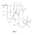
- an ignition coil 1 is controlled by a circuit 2, the ignition device being energized by a contact 4, produced by the ignition key, disposed between the positive terminal of the battery 3 and the ignition coil 1, in order to provide the necessary energy the operation of at least one spark plug 5.
- a circuit for protection against parasitic ignitions connects the coil 1 to the positive terminal of the battery and consists of two transistors 6 and 7, two diodes 11 and 12, two capacitive elements 10 and 13 and two resistors 8 and 9.
- the collector-emitter junction of transistor 6, of the NPN type is connected in parallel to the terminals of the ignition key 4 and provides the direct connection between the coil 1 and the battery 3.
- the emitter of transistor 7, of PNP type is connected to the positive terminal of the battery, its collector at the base of the transistor 6, and its base between the two resistors 8 and 9 which are in series with the capacitive element 10, this assembly constitutes elements 8 to 10 being connected in parallel to contact 4, the diode 11 is connected in parallel to the resistors 8 and 9 passing from the capacitive element 10 to the battery 3, the diode 12 is connected passing from the positive terminal of the coil 1 to the battery 3 and the capacitive element 13 connects the positive terminal of the coil 1 to ground.
- the voltage Uc across the terminals of the capacitive element 10 becomes zero, the transistor 7 becomes saturated, as well as the transistor 6, the voltage Us is 14V minus the junction voltage of the transistor 6.
- the coil 1 is then supplied directly by the battery without passing through the contact 4. If the opening is very brief, of the order of one second for example, the voltage Us remains practically constant during the overvoltage.
- the capacitive element 10 charges through the resistors 8 and 9, the base-emitter voltage of the tansistor 7 decreases, as does that of the transistor 6, which gradually blocks, the voltage Us decreases until to zero after about 3.5s.
- the diode 12 protects the transistor 6 against reverse overvoltages and the capacitive element 13 blocks the parasitic voltages which would prevent the charging of the element 10 when the contact 4 is open.
Landscapes
- Engineering & Computer Science (AREA)
- Chemical & Material Sciences (AREA)
- Combustion & Propulsion (AREA)
- Mechanical Engineering (AREA)
- General Engineering & Computer Science (AREA)
- Ignition Installations For Internal Combustion Engines (AREA)
Applications Claiming Priority (2)
| Application Number | Priority Date | Filing Date | Title |
|---|---|---|---|
| FR8403199 | 1984-03-01 | ||
| FR8403199A FR2560646B1 (fr) | 1984-03-01 | 1984-03-01 | Dispositif de protection pour systeme d'allumage de vehicule automobile |
Publications (2)
| Publication Number | Publication Date |
|---|---|
| EP0154567A1 true EP0154567A1 (de) | 1985-09-11 |
| EP0154567B1 EP0154567B1 (de) | 1988-07-06 |
Family
ID=9301578
Family Applications (1)
| Application Number | Title | Priority Date | Filing Date |
|---|---|---|---|
| EP19850400021 Expired EP0154567B1 (de) | 1984-03-01 | 1985-01-08 | Schutzeinrichtung für ein Zündsystem eines Kraftfahrzeuges |
Country Status (3)
| Country | Link |
|---|---|
| EP (1) | EP0154567B1 (de) |
| DE (1) | DE3563645D1 (de) |
| FR (1) | FR2560646B1 (de) |
Citations (3)
| Publication number | Priority date | Publication date | Assignee | Title |
|---|---|---|---|---|
| US3745985A (en) * | 1970-09-28 | 1973-07-17 | Bosch Gmbh Robert | Arrangement for preventing current flow in the ignition coil of an internal combustion engine during standstill conditions |
| US3854466A (en) * | 1971-07-24 | 1974-12-17 | Bosch Gmbh Robert | Ignition system for an internal combustion engine |
| FR2240648A5 (de) * | 1973-08-07 | 1975-03-07 | Bosch Gmbh Robert |
-
1984
- 1984-03-01 FR FR8403199A patent/FR2560646B1/fr not_active Expired
-
1985
- 1985-01-08 DE DE8585400021T patent/DE3563645D1/de not_active Expired
- 1985-01-08 EP EP19850400021 patent/EP0154567B1/de not_active Expired
Patent Citations (3)
| Publication number | Priority date | Publication date | Assignee | Title |
|---|---|---|---|---|
| US3745985A (en) * | 1970-09-28 | 1973-07-17 | Bosch Gmbh Robert | Arrangement for preventing current flow in the ignition coil of an internal combustion engine during standstill conditions |
| US3854466A (en) * | 1971-07-24 | 1974-12-17 | Bosch Gmbh Robert | Ignition system for an internal combustion engine |
| FR2240648A5 (de) * | 1973-08-07 | 1975-03-07 | Bosch Gmbh Robert |
Also Published As
| Publication number | Publication date |
|---|---|
| DE3563645D1 (en) | 1988-08-11 |
| FR2560646B1 (fr) | 1986-08-29 |
| FR2560646A1 (fr) | 1985-09-06 |
| EP0154567B1 (de) | 1988-07-06 |
Similar Documents
| Publication | Publication Date | Title |
|---|---|---|
| US8605408B2 (en) | Power semiconductor device for igniter | |
| US4479467A (en) | Multiple spark CD ignition system | |
| WO1992008048A3 (en) | Electrical circuit | |
| FR2742600A1 (fr) | Circuit electronique a protection contre une inversion de poles | |
| US4171687A (en) | Revolution limiters | |
| US4893605A (en) | Ignition device for internal combustion engine | |
| EP0026138A1 (de) | Elektronische Vorrichtung zum Steuern der Zündspule einer Brennkraftmaschine und Brennkraftmaschine mit einer solchen Vorrichtung | |
| EP0154567B1 (de) | Schutzeinrichtung für ein Zündsystem eines Kraftfahrzeuges | |
| JPH0670422B2 (ja) | 内燃機関の回転数制御装置 | |
| US4064415A (en) | Inductive spark ignition for combustion engine | |
| EP0505234B1 (de) | Schaltkreis zur Erkennung eines Schalterzustandes, namentlich eines Zündschlüssels in einem Spannungsregler eines Wechselstromgenerators | |
| US4738239A (en) | Ignition system | |
| JPS6217676B2 (de) | ||
| ES2184051T3 (es) | Sistema de ignicion con comando de distribucion de la tension del generador. | |
| EP0268528B1 (de) | Zündanlage für Brennkraftmaschine | |
| FR2675206A1 (fr) | Procede et dispositif de detection d'un rate d'allumage dans un moteur a combustion interne et leurs applications. | |
| FR2564264A1 (fr) | Relais statique pour courant continu | |
| GB1604453A (en) | Starting systems for internal combustion engines | |
| GB1501621A (en) | Spark ignition systems for internal combustion engines | |
| EP1113352B1 (de) | Steuervorrichtung | |
| EP0559540A1 (de) | Elektronische Zündungsvorrichtung mit Spule für Brennkraftmaschine mit gesteuerter Zündung | |
| FR2733097A1 (fr) | Circuit d'excitation d'alternateur notamment de vehicule automobile, et regulateur et alternateur l'incorporant | |
| FR2755321A1 (fr) | Dispositif de commande pour une generatrice de vehicule | |
| US3476097A (en) | Spark ignition systems for internal combustion engines | |
| JPH0437277B2 (de) |
Legal Events
| Date | Code | Title | Description |
|---|---|---|---|
| PUAI | Public reference made under article 153(3) epc to a published international application that has entered the european phase |
Free format text: ORIGINAL CODE: 0009012 |
|
| AK | Designated contracting states |
Designated state(s): DE GB IT |
|
| 17P | Request for examination filed |
Effective date: 19851108 |
|
| 17Q | First examination report despatched |
Effective date: 19870707 |
|
| GRAA | (expected) grant |
Free format text: ORIGINAL CODE: 0009210 |
|
| AK | Designated contracting states |
Kind code of ref document: B1 Designated state(s): DE GB IT |
|
| GBT | Gb: translation of ep patent filed (gb section 77(6)(a)/1977) | ||
| REF | Corresponds to: |
Ref document number: 3563645 Country of ref document: DE Date of ref document: 19880811 |
|
| ITF | It: translation for a ep patent filed | ||
| PGFP | Annual fee paid to national office [announced via postgrant information from national office to epo] |
Ref country code: GB Payment date: 19890108 Year of fee payment: 5 |
|
| PLBE | No opposition filed within time limit |
Free format text: ORIGINAL CODE: 0009261 |
|
| STAA | Information on the status of an ep patent application or granted ep patent |
Free format text: STATUS: NO OPPOSITION FILED WITHIN TIME LIMIT |
|
| 26N | No opposition filed | ||
| PG25 | Lapsed in a contracting state [announced via postgrant information from national office to epo] |
Ref country code: DE Effective date: 19891003 |
|
| PG25 | Lapsed in a contracting state [announced via postgrant information from national office to epo] |
Ref country code: GB Effective date: 19900108 |
|
| GBPC | Gb: european patent ceased through non-payment of renewal fee |