EP0154580B1 - Retard d'initiation pour tête militaire à charges formées montées en tandem - Google Patents
Retard d'initiation pour tête militaire à charges formées montées en tandem Download PDFInfo
- Publication number
- EP0154580B1 EP0154580B1 EP85400249A EP85400249A EP0154580B1 EP 0154580 B1 EP0154580 B1 EP 0154580B1 EP 85400249 A EP85400249 A EP 85400249A EP 85400249 A EP85400249 A EP 85400249A EP 0154580 B1 EP0154580 B1 EP 0154580B1
- Authority
- EP
- European Patent Office
- Prior art keywords
- initiation
- screen
- charge
- retarder
- delay
- Prior art date
- Legal status (The legal status is an assumption and is not a legal conclusion. Google has not performed a legal analysis and makes no representation as to the accuracy of the status listed.)
- Expired
Links
Images

Classifications
-
- F—MECHANICAL ENGINEERING; LIGHTING; HEATING; WEAPONS; BLASTING
- F42—AMMUNITION; BLASTING
- F42C—AMMUNITION FUZES; ARMING OR SAFETY MEANS THEREFOR
- F42C19/00—Details of fuzes
- F42C19/06—Electric contact parts specially adapted for use with electric fuzes
-
- F—MECHANICAL ENGINEERING; LIGHTING; HEATING; WEAPONS; BLASTING
- F42—AMMUNITION; BLASTING
- F42B—EXPLOSIVE CHARGES, e.g. FOR BLASTING, FIREWORKS, AMMUNITION
- F42B12/00—Projectiles, missiles or mines characterised by the warhead, the intended effect, or the material
- F42B12/02—Projectiles, missiles or mines characterised by the warhead, the intended effect, or the material characterised by the warhead or the intended effect
- F42B12/04—Projectiles, missiles or mines characterised by the warhead, the intended effect, or the material characterised by the warhead or the intended effect of armour-piercing type
- F42B12/10—Projectiles, missiles or mines characterised by the warhead, the intended effect, or the material characterised by the warhead or the intended effect of armour-piercing type with shaped or hollow charge
- F42B12/16—Projectiles, missiles or mines characterised by the warhead, the intended effect, or the material characterised by the warhead or the intended effect of armour-piercing type with shaped or hollow charge in combination with an additional projectile or charge, acting successively on the target
- F42B12/18—Hollow charges in tandem arrangement
Definitions
- the present invention relates to an initiation delay for a military head comprising two formed charges mounted in tandem and initiated successively. The front charge is initiated first, then with a pre-determined delay, the rear charge detonates.
- Delay of a few hundred microseconds could be carried out without problem by a winding of detonating cord, but for a delay time greater than 0.5 ms, the length of ring used becomes prohibitive. Indeed, it is necessary to use 3.5 m of cord for a delay of 0.5 ms or 10.5 m for 1.5 ms. These long lengths pose a major problem due to their large size.
- the prevet US-A-4 004 515 describes a military head made up of two charges mounted in tandem. It comprises a formed rear chage and a frustoconical front load provided with a hole at its top; these two charges are separated by a tube and a plate which is not a screen.
- the rear load is first initiated, because it is the main load of the system and it generates a perforation jet through the tube. The rear part of the jet interferes with the tube, causing the plate to move.
- the impact of this plate on the front load causes its initiation to produce a second hollow charge jet after a delay of 30 to 50 ms, a delay which is incompatible with the requirements of the invention.
- the patent FR-A-1 091 932 describes a conventional device for initiating a hollow charge comprising, inter alia, a piezoelectric element whose deformation on impact generates an initiating current of the initiating composition. It is therefore a deformation in contact with the target itself.
- the invention therefore aims to overcome the drawbacks of the state of the art by proposing a device for delay congestion reduced and high precision.
- the invention consists in using the known screen arranged between the two charges to achieve the delay. Indeed, it has been shown that it is necessary to use a protective structure or screen to ensure the protection of the rear load when the front load is operating. It was found that this screen, under the action of the detonation of the first charge, moves towards the rear of the military head and possibly deforms. The invention therefore consists in taking advantage of the displacement of this screen to ensure the delay in operation of the rear load.
- the subject of the invention is therefore an initiation delay for a military head comprising a front formed charge and a rear formed charge mounted in tandem, the rear charge being initiated after a predetermined delay relative to the initiation of the front charge, a electrical circuit for initiating the rear charge and a screen arranged between the two charges and movable towards the rear in a final position under the effect of the detonation of the front charge, characterized in that it is constituted by the screen itself, the travel time between its initial position and its final position defines the initiation delay, the screen controlling during its movement the closing of the electrical circuit.
- the screen comprises an electrically conductive part cooperating with contactors to ensure, during its passage to the final position, the closing of the electrical circuit.
- the screen impacts, during its passage to the final position, a piezoelectric device delivering an electrical control signal necessary for the initiation of the rear load.
- the piezoelectric device consists of piezoelectric pellets arranged annularly around the periphery of the military head.
- the screen is made of magnetic material and passes during its passage to the second position, a coil generating an electrical control signal necessary for the initiation of the rear load.
- the initiation delay is between 0.5 and 3 ms.
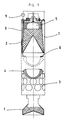
- the military head shown in FIG. 1 comprises a charge formed before 1 of the flat charge type and a charge formed rear 2 of the hollow charge type.
- the two charges are arranged in a fragmentable shell 3.
- a screen 4 is placed between the two charges formed so as to protect the rear charge during the detonation of the front charge.
- the initiation of the two charges formed is done via priming systems 5 known to those skilled in the art.
- contactors 6 are arranged between the screen 4 and the rear load 2. These contactors are connected, by means of electrical lines 7 and 8 to a source of electrical energy 9 and to the rear load initiator.
- the screen moves towards the rear of the military head and strikes the contactors 6 which close the electrical circuit and ensures the operation of the device for initiating the rear load.
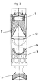
- FIG. 2 represents a variant of FIG. 1, in this case, the contactors 6 are replaced by piezoelectric elements 10 which, upon impact by the screen 4, deliver an electrical control signal which can be used either directly to initiate the device for initiating the rear load , either indirectly to initiate a known electronic system, the role of which is to supply energy to the ignition device by an additional source of electricity.
- FIG. 3 represents a military head comprising an induction coil 11 disposed between the rear load and the screen 4.
- the screen is made up of a magnetic material and induces an electric current when it crosses the coil 11. This current, as in the case shown in the previous figure, can be used directly or indirectly to initiate the rear load.
- the displacement of the screen must remain less than the initial distance between screen and rear load during the time interval which separates the two firings.
- the speed of the screen is 24 m / s; thus for a desired delay of 1 ms, the screen will have to move 24 mm to ensure the operation of the rear load.
- An advantage of this device lies in the fact that the phenomenon of screen 4 recoil is very reproducible, which makes it possible to obtain delay times of high precision.
Landscapes
- Engineering & Computer Science (AREA)
- General Engineering & Computer Science (AREA)
- Chemical & Material Sciences (AREA)
- Combustion & Propulsion (AREA)
- Air Bags (AREA)
- Aiming, Guidance, Guns With A Light Source, Armor, Camouflage, And Targets (AREA)
- Pinball Game Machines (AREA)
Description
- La présente invention concerne un retard d'initiation pour tête militaire comportant deux charges formées montées en tandem et initiées successivement. La charge avant est initiée en premier, puis avec un retard pré-déterminé, la charge arrière détone.
- Les caractéristiques décrites dans le préambule de la revendication 1 sont réunis dans un dispositif qui, de par son usage connu, fait partie de l'état de la technique.
- Les travaux relatifs à l'optimisation de la conception des montages de charges formées en tandem efficaces contre un ensemble de configuration de blindages actifs, montrent que l'intervalle de temps entre la mise à feu des deux charges doit être au moins égal à 1,5 ms, voire de 2 ms.
- La réalisation de retard de quelques centaines de micro-secondes pourrait être effectuée sans problème par un enroulement de cordeau détonant, mais pour une durée de retard supérieure à 0, 5 ms, la longueur de courdeau mise en oeuvre devient prohibitive. En effet, il est nécessaire d'utiliser 3,5 m de cordeau pour un retard de 0,5 ms soit 10,5 m pour 1,5 ms. Ces grandes longueurs posent un problème majeur dû à leur encombrement important.
- Par ailleurs, la précision demandée à de tels retards (mieux que 5%) est incompatible avec les systèmes pyrotechniques classiques basés sur les phénomènes de transition combustion-détonation et utilisant des explosifs primaires.
- Le prevet US-A-4 004 515 décrit une tête militaire constituée de deux charges montées en tandem. Elle comprend une chage arrière formée et une charge avant tronconique munie d'un trou à son sommet; ces deux charges sont séparées par un tube et une plaque qui n'est pas un écran. La charge arrière est d'abord initiée, car c'est la charge principale du système et elle génère un jet de perforation à travers le tube. La partie arrière du jet interfère avec le tube, ce qui provoque le déplacement de la plaque. Le choc de cette plaque sur la charge avant provoque son initiation pour produire un second jet de charge creuse après un délai de 30 à 50 ms, délai qui est incompatible avec les impératifs de l'invention.
- Le brevet FR-A-1 091 932 décrit un dispositif classique d'amorçage d'une charge creuse comprenant entre autres, un élément piézoélectrique dont la déformation à l'impact engendre un courant d'initiation de la composition d'amorçage. Il s'agit donc d'une déformation au contact de la cible même.
- L'invention vise donc à pallier les inconvénients de l'état de la technique en proposant un dispositif de retard d'encombrement réduit et de grande précision.
- L'invention consiste à utiliser l'écran connu disposé entre les deux charges pour réaliser le retard. En effet, il a été montré qu'il est nécessaire d'utiliser une structure protectrice ou écran pour assurer la protection de la charge arrière lorsque la charge avant fonctionne. On a constaté que cet écran, sous l'action de la détonation de la première charge, se déplace vers l'arrière de la tête militaire et éventuellement se déforme. L'invention consiste donc à mettre à profit le déplacement de cet écran pour assurer le retard de fonctionnement de la charge arrière.
- L'invention a donc pour objet un retard d'initiation pour tête militaire comprenant une charge formée avant et une charge formée arrière montées en tandem, la charge arrière étant initiée après un délai prédéterminée par rapport à l'initiation de la charge avant, un circuit électrique d'initiation de la charge arrière et un écran disposé entre les deux charges et mobile vers l'arrière dans une position finale sous l'effet de la détonation de la charge avant, caractérisé en ce qu'il est constitué par l'écran lui-même dont le temps de parcours entre sa position initiale et sa position finale définit le délai d'initiation, l'écran commandant au cours de son déplacement la fermeture de circuit électrique.
- L'écran comporte une partie conductrice d'électricité coopérant avec des contacteurs pour assurer lors de son passage à la position finale la fermeture du circuit électrique.
- L'écran impacte, lors de son passage à la position finale, un dispositif piézoélectrique délivrant un signal de commande électrique nécessaire à l'initiation de la charge arrière.
- Le dispositif piézoélectrique est constitué de pastilles piézoélectriques disposées de façon annulaire sur le pourtour de la tête militaire.
- L'écran est en matériau magnétique et traverse lors de son passage à la seconde position, une bobine générant un signal de commande électrique nécessaire à l'initiation de la charge arrière.
- Le délai d'initiation est compris entre 0,5 et 3 ms.
- L'invention sera mieux comprise à l'aide de la description qui va suivre, faite au regard des dessins annexés, sur lesquels:
- la figure 1 représente une coupe longitudinale d'un exemple particulier de réalisatoin de l'invention,
- la figure 2 représente une première variante selon l'invention,
- la figure 3 représente une deuxième variante de l'invention.
- La tête militaire représentée à la figure 1 comporte une charge formée avant 1 du type charge plate et une charge formée arrière 2 du type charge creuse. Les deux charges sont disposées dans une virole fragmentable 3. Un écran 4 est placé entre les deux charges formées de manière à protéger la charge arrière lors de la détonation de la charge avant.
- L'initiation des deux charges formées se fait par l'intermédiaire de systèmes d'amorçage 5 connus de l'homme de l'art.
- Toutefois, l'initiation de la charge arrière 2 se fait avec un retard prédéterminé par rapport à l'amorçage de la charge avant. Selon l'exemple particulier de la figure 1, des contacteurs 6 sont disposés entre l'écran 4 et la charge arrière 2. Ces contacteurs sont reliés, par l'intermédiaire de lignes électriques 7 et 8 à une source d'énergie électrique 9 et au dispositif d'amorçage de la charge arrière.
- Ainsi, lors de la détonation de la charge avant, l'écran se déplace vers l'arrière de la tête militaire et vient heurter les contacteurs 6 qui ferment le circuit électrique et assure le fonctionnement du dispositif d'amorçage de la charge arrière.
- La figure 2 représente une variante de la figure 1, dans ce cas, les contacteurs 6 sont remplacés par des éléments piézoélectriques 10 qui, lors de l'impact par l'écran 4, délivrent un signal de commande électrique qui peut être utilisé soit directement pour initier le dispositif d'amorçage de la charge arrière, soit indirectement pour initier un système électronique connu dont le rôle est de fournir de l'énergie au dispositif d'amorçage par une source d'électricité annexe.
- La figure 3 représente une tête militaire comprenant une bobine d'induction 11 disposée entre la charge arrière et l'écran 4. Dans ce cas particulier, l'écran est constitué par une matière magnétique et induit un courant électrique lorsqu'il traverse la bobine 11. Ce courant, comme dans le cas représenté à la figure précédente, peut être utilisé directement ou indirectement pour amorcer la charge arrière.
- Dans tous les cas, pour que le système fonctionne de façon satisfaisante, il faut que le déplacement de l'écran reste inférieur à la distance initiale écran- charge arrière pendant l'intervalle de temps qui sépare les deux mises à feu. A titre d'exemple, pour une tête militaire telle que représentée aux diverses figures, la vitesse de l'écran est de 24 m/s; ainsi pour un retard souhaité de 1 ms, l'écran devra se déplacer de 24 mm pour assurer le fonctionnement de la charge arrière.
- Un avantage de ce dispositif tient au fait que le phénomène de recul de l'écran 4 est très reproductible, ce qui permet d'obtenir des temps de retard d'une grande précision.
- Un autre avantage provient du fait que l'écran 4 assure une fonction supplémentaire de celle qu'il jouait auparavant, ce qui ne complique pas le dispositif et permet de réaliser une tête militaire très compacte pouvant être intégrée facilement à tous projectiles.
Claims (6)
Applications Claiming Priority (2)
| Application Number | Priority Date | Filing Date | Title |
|---|---|---|---|
| FR8402487A FR2559896B1 (fr) | 1984-02-20 | 1984-02-20 | Retard d'initiation pour tete militaire a charges formees montees en tandem |
| FR8402487 | 1984-02-20 |
Publications (2)
| Publication Number | Publication Date |
|---|---|
| EP0154580A1 EP0154580A1 (fr) | 1985-09-11 |
| EP0154580B1 true EP0154580B1 (fr) | 1988-01-07 |
Family
ID=9301165
Family Applications (1)
| Application Number | Title | Priority Date | Filing Date |
|---|---|---|---|
| EP85400249A Expired EP0154580B1 (fr) | 1984-02-20 | 1985-02-14 | Retard d'initiation pour tête militaire à charges formées montées en tandem |
Country Status (5)
| Country | Link |
|---|---|
| US (1) | US4606272A (fr) |
| EP (1) | EP0154580B1 (fr) |
| CA (1) | CA1268663A (fr) |
| DE (1) | DE3561364D1 (fr) |
| FR (1) | FR2559896B1 (fr) |
Cited By (1)
| Publication number | Priority date | Publication date | Assignee | Title |
|---|---|---|---|---|
| DE4135392A1 (de) * | 1991-10-26 | 1993-04-29 | Deutsche Aerospace | Gefechtskopf |
Families Citing this family (25)
| Publication number | Priority date | Publication date | Assignee | Title |
|---|---|---|---|---|
| DE3605580C1 (de) * | 1986-02-21 | 1987-06-04 | Messerschmitt Boelkow Blohm | Gefechtskopf |
| GB8620138D0 (en) * | 1986-08-19 | 1994-01-26 | British Aerospace | Projectile warhead |
| FR2603375B1 (fr) * | 1986-08-26 | 1990-07-27 | Matra Manurhin Defense | Munition a charges en tandem |
| IL81097A (en) * | 1986-12-25 | 1991-06-10 | Israel Defence | Two-stage shaped charge projectile |
| US5033382A (en) * | 1987-03-25 | 1991-07-23 | Magnavox Government And Industrial Electronics Company | Piezoelectric fuse for projectile with safe and arm mechanism |
| US4793256A (en) * | 1987-03-25 | 1988-12-27 | Magnavox Government And Industrial Electronics Company | Piezoelectric fuse for projectile with safe and arm mechanism |
| DE3740412C1 (de) * | 1987-11-28 | 1996-04-25 | Rheinmetall Ind Gmbh | Gefechtskopf |
| US7493861B1 (en) * | 1989-07-24 | 2009-02-24 | The United States Of America As Represented By The Secretary Of The Army | Tandem shaped charge warhead having a confined forward charge and a light-weight blast shield |
| FR2660427B1 (fr) * | 1990-03-29 | 1993-12-31 | Giat Industries | Retard d'initiation pour charges formees detonant en sequence. |
| FR2729750B1 (fr) * | 1990-03-29 | 1997-03-21 | France Etat | Tete militaire a charges creuses en sequence |
| DE4130646C2 (de) * | 1990-09-28 | 2000-02-03 | Dynamit Nobel Ag | Verfahren zum Auslösen eines Explosivkörpers |
| US5565647A (en) * | 1991-05-24 | 1996-10-15 | Giat Industries | Warhead with sequential shape charges |
| US5111746A (en) * | 1991-06-21 | 1992-05-12 | The United States Of America As Represented By The Secretary Of The Army | Multiple stage munition |
| DE4126793C1 (de) * | 1991-08-14 | 1994-05-11 | Deutsche Aerospace | Tandemgefechtskopf |
| DE4240084A1 (de) * | 1992-11-28 | 1994-06-01 | Dynamit Nobel Ag | Tandemgefechtskopf mit piezoelektrischen Aufschlagzündern |
| FR2718842B1 (fr) * | 1994-04-15 | 1996-06-28 | Luchaire Defense Sa | Projectile destiné à agresser des cibles dures. |
| US5526752A (en) | 1994-09-06 | 1996-06-18 | Rockwell International Corporation | Weapon for destruction of deeply buried and hardened targets |
| DE19540863B3 (de) * | 1995-11-02 | 2013-12-05 | Nexter Munitions | Zündvorrichtung |
| SE9601114L (sv) * | 1996-03-22 | 1997-07-14 | Bofors Ab | Ammunitionsanordning i form av granat eller liknande |
| DE19706688C1 (de) * | 1997-02-20 | 1998-09-24 | Daimler Benz Aerospace Ag | Gefechtskopf mit einem Vorwirkkörper und einem Nachwirkkörper |
| US6305289B1 (en) * | 1998-09-30 | 2001-10-23 | Western Atlas International, Inc. | Shaped charge for large diameter perforations |
| RU2406059C1 (ru) * | 2009-07-14 | 2010-12-10 | Государственное унитарное предприятие "Конструкторское бюро приборостроения" | Граната |
| FR2953009A1 (fr) | 2009-11-26 | 2011-05-27 | Nexter Munitions | Tete militaire a charges en tandem |
| US9612095B2 (en) * | 2014-12-12 | 2017-04-04 | Schlumberger Technology Corporation | Composite shaped charges |
| DE102023000642B3 (de) | 2023-02-22 | 2024-01-25 | Bundesrepublik Deutschland, vertr. durch das Bundesministerium der Verteidigung, vertr. durch das Bundesamt für Ausrüstung, Informationstechnik und Nutzung der Bundeswehr | Gefechtskopf mit einer Vorhohlladung und einer Haupthohlladung |
Family Cites Families (10)
| Publication number | Priority date | Publication date | Assignee | Title |
|---|---|---|---|---|
| CA731987A (en) * | 1966-04-12 | Jersey Production Research Company | Well perforating | |
| BE526010A (fr) * | 1953-01-27 | |||
| US3320890A (en) * | 1965-05-06 | 1967-05-23 | Thomas Q Ciccone | Piezo-electric detonation initiator system |
| BE740812A (fr) * | 1969-10-27 | 1970-07-27 | ||
| US4004515A (en) * | 1971-01-25 | 1977-01-25 | The United States Of America As Represented By The Secretary Of The Navy | Sequential jet shaped charge |
| FR2365774A1 (fr) * | 1976-09-27 | 1978-04-21 | Serat | Perfectionnements aux chargements des projectiles |
| FR2410243A1 (fr) * | 1977-11-24 | 1979-06-22 | Serat | Perfectionnements apportes aux charges creuses |
| DE2847548C2 (de) * | 1978-11-02 | 1983-03-03 | Diehl GmbH & Co, 8500 Nürnberg | Elektrischer Geschoßzünder |
| DE3165351D1 (en) * | 1980-05-09 | 1984-09-13 | Emi Ltd | Arrangements for igniting a pyrotechnic charge |
| US4402269A (en) * | 1981-06-29 | 1983-09-06 | The United States Of America As Represented By The Secretary Of The Navy | Electric delay detonator |
-
1984
- 1984-02-20 FR FR8402487A patent/FR2559896B1/fr not_active Expired
-
1985
- 1985-02-12 US US06/701,033 patent/US4606272A/en not_active Expired - Lifetime
- 1985-02-14 EP EP85400249A patent/EP0154580B1/fr not_active Expired
- 1985-02-14 DE DE8585400249T patent/DE3561364D1/de not_active Expired
- 1985-02-19 CA CA000474662A patent/CA1268663A/fr not_active Expired - Lifetime
Cited By (1)
| Publication number | Priority date | Publication date | Assignee | Title |
|---|---|---|---|---|
| DE4135392A1 (de) * | 1991-10-26 | 1993-04-29 | Deutsche Aerospace | Gefechtskopf |
Also Published As
| Publication number | Publication date |
|---|---|
| CA1268663A (fr) | 1990-05-08 |
| US4606272A (en) | 1986-08-19 |
| DE3561364D1 (en) | 1988-02-11 |
| FR2559896B1 (fr) | 1987-09-25 |
| EP0154580A1 (fr) | 1985-09-11 |
| FR2559896A1 (fr) | 1985-08-23 |
Similar Documents
| Publication | Publication Date | Title |
|---|---|---|
| EP0154580B1 (fr) | Retard d'initiation pour tête militaire à charges formées montées en tandem | |
| EP0010487B1 (fr) | Initiateur d'allumage à fil chaud de charges propulsives | |
| FR2537264A1 (fr) | Projectile de perforation ou de rupture de blindage | |
| CH654104A5 (fr) | Ensemble explosif hybride. | |
| EP0221218B1 (fr) | Tête militaire à charges formées montées en tandem | |
| FR3017205A1 (fr) | Charge creuse et application pour la separation de deux etages d'un engin aeronautique ou sa neutralisation | |
| FR2483160A5 (fr) | Dispositif de declenchement a sensibilite preetablie pour amorcage electrique de mine | |
| EP0474855B1 (fr) | Retard d'initiation pour charges formees detonant en sequence | |
| USH1366H (en) | SCB initiator | |
| FR2771499A1 (fr) | Dispositif de declenchement de l'allumage d'un projectile anti-abri | |
| FR2903770A1 (fr) | Sandwich electromagnetique | |
| EP1767894B1 (fr) | Dispositif embarqué de génération de décharges plasma pour le pilotage d'un engin supersonique ou hypersonique | |
| EP0296962A1 (fr) | Inflamatteur pour générateur pyrotechnique | |
| EP1672308B1 (fr) | Disposition d'initiation pour charge explosive ou composition pyrotechnique | |
| EP2827091B1 (fr) | Initiateur électrique ayant deux modes de fonctionnement | |
| FR2643142A1 (fr) | Canon a tir unique avec dispositif d'acceleration electromagnetique | |
| FR2552871A1 (fr) | Projectile antichar agissant en vitesse defilante | |
| FR2612706A1 (fr) | Source impulsionnelle de courant electrique et canon electromagnetique en faisant application | |
| FR2601763A1 (fr) | Projectile sous-calibre de type fleche pour blindages actifs | |
| RU2131581C1 (ru) | Способ защиты боевой части тандемного боеприпаса и тандемный боеприпас | |
| FR2792717A1 (fr) | Projectile a charge creuse comportant un ecran, a encombrement reduit | |
| EP0303539A1 (fr) | Dispositif de selection et de déclenchement de circuit de mise à feu | |
| FR2867848A1 (fr) | Dispositif d'initiation de deux charges explosives et tete militaire mettant en oeuvre un tel dispositif d'initiation | |
| EP0113270B1 (fr) | Système d'amorçage pour dispositif explosif, créant une onde de détonation radiale | |
| EP1269105B1 (fr) | Charge pyrotechnique a fonctionnement dual |
Legal Events
| Date | Code | Title | Description |
|---|---|---|---|
| PUAI | Public reference made under article 153(3) epc to a published international application that has entered the european phase |
Free format text: ORIGINAL CODE: 0009012 |
|
| 17P | Request for examination filed |
Effective date: 19850221 |
|
| AK | Designated contracting states |
Designated state(s): DE GB IT |
|
| 17Q | First examination report despatched |
Effective date: 19860527 |
|
| GRAA | (expected) grant |
Free format text: ORIGINAL CODE: 0009210 |
|
| AK | Designated contracting states |
Kind code of ref document: B1 Designated state(s): DE GB IT |
|
| ITF | It: translation for a ep patent filed | ||
| REF | Corresponds to: |
Ref document number: 3561364 Country of ref document: DE Date of ref document: 19880211 |
|
| GBT | Gb: translation of ep patent filed (gb section 77(6)(a)/1977) | ||
| PLBE | No opposition filed within time limit |
Free format text: ORIGINAL CODE: 0009261 |
|
| STAA | Information on the status of an ep patent application or granted ep patent |
Free format text: STATUS: NO OPPOSITION FILED WITHIN TIME LIMIT |
|
| 26N | No opposition filed | ||
| ITTA | It: last paid annual fee | ||
| ITPR | It: changes in ownership of a european patent |
Owner name: CESSIONE;GIAT INDUSTRIES |
|
| REG | Reference to a national code |
Ref country code: GB Ref legal event code: 732 |
|
| REG | Reference to a national code |
Ref country code: GB Ref legal event code: IF02 |
|
| PGFP | Annual fee paid to national office [announced via postgrant information from national office to epo] |
Ref country code: DE Payment date: 20020212 Year of fee payment: 18 |
|
| PGFP | Annual fee paid to national office [announced via postgrant information from national office to epo] |
Ref country code: GB Payment date: 20030124 Year of fee payment: 19 |
|
| PG25 | Lapsed in a contracting state [announced via postgrant information from national office to epo] |
Ref country code: DE Free format text: LAPSE BECAUSE OF NON-PAYMENT OF DUE FEES Effective date: 20030902 |
|
| PG25 | Lapsed in a contracting state [announced via postgrant information from national office to epo] |
Ref country code: GB Free format text: LAPSE BECAUSE OF NON-PAYMENT OF DUE FEES Effective date: 20040214 |
|
| GBPC | Gb: european patent ceased through non-payment of renewal fee |
Effective date: 20040214 |