EP0154606A2 - Schwingungsvorrichtung zum Bewegen von Werkstücken in Anlagen zur Oberflächenbehandlung - Google Patents
Schwingungsvorrichtung zum Bewegen von Werkstücken in Anlagen zur Oberflächenbehandlung Download PDFInfo
- Publication number
- EP0154606A2 EP0154606A2 EP85810071A EP85810071A EP0154606A2 EP 0154606 A2 EP0154606 A2 EP 0154606A2 EP 85810071 A EP85810071 A EP 85810071A EP 85810071 A EP85810071 A EP 85810071A EP 0154606 A2 EP0154606 A2 EP 0154606A2
- Authority
- EP
- European Patent Office
- Prior art keywords
- oscillator
- tanks
- tank
- container
- conduits
- Prior art date
- Legal status (The legal status is an assumption and is not a legal conclusion. Google has not performed a legal analysis and makes no representation as to the accuracy of the status listed.)
- Granted
Links
Images

Classifications
-
- B—PERFORMING OPERATIONS; TRANSPORTING
- B06—GENERATING OR TRANSMITTING MECHANICAL VIBRATIONS IN GENERAL
- B06B—METHODS OR APPARATUS FOR GENERATING OR TRANSMITTING MECHANICAL VIBRATIONS OF INFRASONIC, SONIC, OR ULTRASONIC FREQUENCY, e.g. FOR PERFORMING MECHANICAL WORK IN GENERAL
- B06B1/00—Methods or apparatus for generating mechanical vibrations of infrasonic, sonic, or ultrasonic frequency
- B06B1/02—Methods or apparatus for generating mechanical vibrations of infrasonic, sonic, or ultrasonic frequency making use of electrical energy
- B06B1/04—Methods or apparatus for generating mechanical vibrations of infrasonic, sonic, or ultrasonic frequency making use of electrical energy operating with electromagnetism
-
- B—PERFORMING OPERATIONS; TRANSPORTING
- B06—GENERATING OR TRANSMITTING MECHANICAL VIBRATIONS IN GENERAL
- B06B—METHODS OR APPARATUS FOR GENERATING OR TRANSMITTING MECHANICAL VIBRATIONS OF INFRASONIC, SONIC, OR ULTRASONIC FREQUENCY, e.g. FOR PERFORMING MECHANICAL WORK IN GENERAL
- B06B1/00—Methods or apparatus for generating mechanical vibrations of infrasonic, sonic, or ultrasonic frequency
- B06B1/10—Methods or apparatus for generating mechanical vibrations of infrasonic, sonic, or ultrasonic frequency making use of mechanical energy
- B06B1/12—Methods or apparatus for generating mechanical vibrations of infrasonic, sonic, or ultrasonic frequency making use of mechanical energy operating with systems involving reciprocating masses
- B06B1/14—Methods or apparatus for generating mechanical vibrations of infrasonic, sonic, or ultrasonic frequency making use of mechanical energy operating with systems involving reciprocating masses the masses being elastically coupled
-
- B—PERFORMING OPERATIONS; TRANSPORTING
- B24—GRINDING; POLISHING
- B24B—MACHINES, DEVICES, OR PROCESSES FOR GRINDING OR POLISHING; DRESSING OR CONDITIONING OF ABRADING SURFACES; FEEDING OF GRINDING, POLISHING, OR LAPPING AGENTS
- B24B31/00—Machines or devices designed for polishing or abrading surfaces on work by means of tumbling apparatus or other apparatus in which the work and/or the abrasive material is loose; Accessories therefor
- B24B31/06—Machines or devices designed for polishing or abrading surfaces on work by means of tumbling apparatus or other apparatus in which the work and/or the abrasive material is loose; Accessories therefor involving oscillating or vibrating containers
-
- H—ELECTRICITY
- H02—GENERATION; CONVERSION OR DISTRIBUTION OF ELECTRIC POWER
- H02K—DYNAMO-ELECTRIC MACHINES
- H02K33/00—Motors with reciprocating, oscillating or vibrating magnet, armature or coil system
Definitions
- the present invention relates to a device for moving parts in a container or bowl on an inclined ramp using rotational vibrations, communicated to the container by an electromagnetic motor.
- Such devices are well known in the industry, in general under the name of vibrators, for example as a means of supplying parts, preferably but not exclusively of small dimensions, of machine tools.
- the parts at the bottom of the container climb the ramp, generally helical in shape, until the work station on the machine using the vibrations of the container.
- oscillator essentially concerns surface treatment installations.
- the oscillator comprising a container and a motor, then has the function of mixing the pieces deposited in the container. These parts, after having climbed the ramp, then fall back to the bottom of the container to start the same cycle a few moments later.
- This device thus advantageously replaces the barrel, well known in conventional electroplating installations, by ensuring more regular mixing.
- a surface treatment installation essentially comprises one or more tanks containing baths, a container in which the parts to be treated are deposited and which it must ensure mixing, means to replace the baths in the tanks and finally, possibly, means to move the container from one tank to another.
- the known oscillators used in this type of installation are constructed so that the container is placed above the motor. This is for example the case of the electroplating installation with a single tank described in patent CH 594072.
- the oscillator is integral with the tank and it is arranged so that the container, placed in the center and inside the tank, is above the engine, located outside. Transmission of the movement from the motor to the container is made using an axis passing through the wall of the tank. It is obvious that this construction poses a sealing problem, which may be difficult to solve with corrosive liquids, at the place where the axis passes through the tank.
- the rigid connection between the oscillator and the tank limits the possibilities of using the installation.
- each tank will be provided with an oscillator in this type of embodiment. This is obviously an expensive and impractical solution, because the transfer of the parts will require detaching each time; the engine container.
- the object of the present invention is to provide an oscillator which does not have the drawbacks of known devices.
- the oscillator according to the invention comprising a container provided with an inclined ramp and capable of receiving the parts to be treated, an oscillating electromagnetic motor, an axis connecting the container to the motor, means for gripping the oscillator, means for placing the oscillator and electrical contact terminals for supplying current to the motor, is particularly remarkable in that the receptacle is arranged below the motor.
- a first advantage of the oscillator according to the invention is to be of simple construction posing no sealing problem.
- a second advantage of the oscillator according to the invention is that it is particularly suitable for use in surface treatment installations with several tanks.
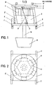
- Figs. 1 and 2 show in elevation and in plan an embodiment of the oscillator according to the invention. It comprises a massive base plate 1, of square shape, made of magnetic material. When the oscillator is in operation, the base plate occupies a horizontal portion.
- Two laying rails 2 are connected to the base plate 1 by means of elastic supports 3 making it possible to filter the vibrations of the oscillator.
- the laying rails 2, or any other similar device, such as a hook make it possible to place the oscillator above a tank on a frame provided for this purpose, secured to the installation.
- six coils 4 are fixed. ugly of a coil support 5.
- Each coil is wound around a magnetic core (not shown) of the same length as the coil.
- the number of coils could be other than six, but not less than three.
- the coils 4 are supplied with current from an electrical distribution box 6, fixed to the base plate 1 and comprising contact terminals.
- This plate is secured to the base plate 1 by means of six identical leaf springs 8.
- Each leaf spring is attached obliquely 'on each of the plates 1 and 7 by means of a bracket 9.
- the upper plate 7 then takes a position parallel to the base plate 1.
- a magnetic frame 10 fixed opposite the coils 4 on the upper plate 7, makes it possible to close the magnetic circuit formed by the cores of the coils 4 and the base plate 1.
- the length of the spring leaves 8 is chosen so that a small space, called the air gap, is formed between the coils 4 and the magnetic armature 10, allowing the plate 7 to perform rotational and translational movements compatible with connections imposed by the spring leaves 8.
- the upper plate 7 is also provided, on the opposite side of the magnetic frame 10, with cheches 11 allowing an external arm, not shown, to grasp and transport the oscillator.
- the elements 1 to 11 which have just been described and their arrangement form the motor of the oscillator. Below this motor is fixed a container 15 by means of a pin 16 anchored in the center of the upper plate 7.
- the container 15 has an inclined ramp not shown and it is preferably made of transparent plastic, for example polyvinyl, to allow observation of the parts inside.
- the operation of the oscillator is as follows.
- this results in an attractive force between the cores of the coils and the magnetic armature 10. From this force results, thanks to the action of the spring blades 8, a movement of vertical translation and rotation about the axis 16 of the upper plate 7 relative to the base plate * 1, assumed to be stationary.
- This movement is naturally transmitted to the container 15.
- the container will also be animated with a periodic oscillatory movement. Thanks to a suitable choice of the shape of the current, its intensity and its frequency, the container 15 can then be animated with a movement conducive to making the pieces climb the inclined ramp and ensuring their mixing.
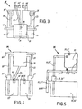
- the installation comprises a certain number of modules M and an embodiment of such a module is shown in FIGS. 3 to 5.
- the module M comprises a tank 21, two tanks 22, 22 ', but their number could be higher, two filling conduits 23, 23', connecting the lower part of each tank 22, 22 'to the part upper part of the tank 21, a movable duct 24, connecting the lower part of the tank 21 either to a drain pipe 25 or 25 ', located at the upper part of each tank 22, 22', or to a duct discharge 26 or 26 ', finally two supply conduits 27, 27', but their number could be higher, ending in the tank 21 above the filling conduits 23, 23 '.
- a drain valve 30 makes it possible, in its open position, to put the bottom of the tank 21 in communication with the movable pipe 24 to which is also connected an overflow pipe 31, fixed inside the tank 21.
- the filling conduits 23, 23 ' each contain a pump 35, 35' and the displacement of one end of the movable conduit 24, putting it in front of one of the emptying conduits 25, 25 'or one of the conduits d 'evacuation 26, 26', is obtained using a control device not shown.
- the transfer of a treatment bath from the reservoir 22 into the tank 21, the drain valve 30 being closed, is carried out by forced circulation of the liquid thanks to the pump 35.
- a rinsing bath of its side, is brought into the tank 21 by a pressurized conduit 27, for example a water pipe, its flow rate being regulated by a valve not shown.
- the return of the treatment bath from the tank 21 into the tank 22 is done, in this construction, by gravity, after having placed the end of the movable duct 24 opposite the drain duct 25, the drain valve 30 being open.
- the rinsing bath is transferred by gravity into the evacuation conduit 26 using the movable conduit 24 placed in an adequate position.
- the circulation of the baths between the tank 21 and the reservoir 22 'or the emptying conduits 25', evacuation 26 'and supply 27' is identical to that which has just been described.
- the tank 21 could be at the same level or even lower than the tanks 22, 22 '.
- pumps could be used in all the conduits to increase the flow rates.
- the movable conduit 24 could also be replaced by fixed conduits, with a valve in each conduit, connecting the bottom of the tank 21 to the emptying conduits 25, 25 'and evacuation 26, 26'.
- Fig. 6 shows a complete installation according to the invention. It is composed, in this example, of six modules M previously described, all identical, except possibly with regard to the number of tanks 22, 22 '.
- a frame 40 surrounding and holding the modules M together, supports two horizontal guide rails 41 and 42 on the rear part of the installation, where the drain 25 and discharge 26 conduits of the modules are located.
- a carriage 43 can move horizontally which supports a movable arm 44 which can slide vertically on this carriage.
- the arm 44 in its low position, can grasp a support 45 to which is fixed an oscillator previously described by the hooks 11 and of which only the container 15 is visible.
- the support 45 contains all the current leads necessary for the operation of the oscillator.
- the support 45 is not in engagement with the arm 44, it rests on a horizontal hanging rail 47 which runs, as well as the rails 41 and 42 along the installation.
- the parts are placed in the container 15 when it is released, out of the modules, in a change position provided for this purpose on the frame 40.
- the arm 44 can raise the container 15 from occupy a high position on the carriage 43. A translation of this carriage along the guide rails 41, 42 makes it possible to bring this container 15 above the module M chosen.
- the position of the container 15, relative to the support 45, is such that the return of the arm 24 in the low position places it at the desired location inside the tank 21 of the module M.
- the support 45 remains in this position, resting on the hanging rail 47 while keeping the oscillator motor out of the bath of the tank 21.
- the arm 44 can then release the support 45 and return to its starting position to grab another oscillator, fixed to a support 45, which would have been loaded in the meantime or move an oscillator from one tank to another.
- the circulation of the baths in the modules M, the movements of the carriage 43 and of the arm 44 are obtained by known devices not shown, controlled from a control cabinet 48 manually or programmed, the latter operating mode being obtained by means of memory devices, such as for example a perforated tape or a magnetic tape.
Landscapes
- Engineering & Computer Science (AREA)
- Mechanical Engineering (AREA)
- Power Engineering (AREA)
- Physics & Mathematics (AREA)
- Electromagnetism (AREA)
- Apparatuses For Generation Of Mechanical Vibrations (AREA)
- Finish Polishing, Edge Sharpening, And Grinding By Specific Grinding Devices (AREA)
- Jigging Conveyors (AREA)
- General Electrical Machinery Utilizing Piezoelectricity, Electrostriction Or Magnetostriction (AREA)
- Coating Apparatus (AREA)
- Cleaning And De-Greasing Of Metallic Materials By Chemical Methods (AREA)
Priority Applications (1)
| Application Number | Priority Date | Filing Date | Title |
|---|---|---|---|
| AT85810071T ATE47808T1 (de) | 1984-03-05 | 1985-02-22 | Schwingungsvorrichtung zum bewegen von werkstuecken in anlagen zur oberflaechenbehandlung. |
Applications Claiming Priority (2)
| Application Number | Priority Date | Filing Date | Title |
|---|---|---|---|
| CH1075/84 | 1984-03-05 | ||
| CH1075/84A CH660994A5 (fr) | 1984-03-05 | 1984-03-05 | Oscillateur et installation de traitement de surface. |
Publications (3)
| Publication Number | Publication Date |
|---|---|
| EP0154606A2 true EP0154606A2 (de) | 1985-09-11 |
| EP0154606A3 EP0154606A3 (en) | 1986-10-22 |
| EP0154606B1 EP0154606B1 (de) | 1989-11-08 |
Family
ID=4201865
Family Applications (1)
| Application Number | Title | Priority Date | Filing Date |
|---|---|---|---|
| EP85810071A Expired EP0154606B1 (de) | 1984-03-05 | 1985-02-22 | Schwingungsvorrichtung zum Bewegen von Werkstücken in Anlagen zur Oberflächenbehandlung |
Country Status (6)
| Country | Link |
|---|---|
| US (1) | US4658953A (de) |
| EP (1) | EP0154606B1 (de) |
| JP (1) | JPS60209420A (de) |
| AT (1) | ATE47808T1 (de) |
| CH (1) | CH660994A5 (de) |
| DE (1) | DE3574112D1 (de) |
Cited By (1)
| Publication number | Priority date | Publication date | Assignee | Title |
|---|---|---|---|---|
| WO2021248726A1 (zh) * | 2020-06-12 | 2021-12-16 | 苏州苏试试验集团股份有限公司 | 一种电动振动台的导向装置及电动振动台 |
Families Citing this family (6)
| Publication number | Priority date | Publication date | Assignee | Title |
|---|---|---|---|---|
| EP0424590A1 (de) * | 1989-10-23 | 1991-05-02 | Elga Sa | Galvanoplastik-Vorrichtung |
| FR2686747A1 (fr) * | 1992-01-16 | 1993-07-30 | Magnin Georges | Dispositif moteur a mouvement alternatif. |
| TW422807B (en) * | 1998-02-23 | 2001-02-21 | Shinko Electric Co Ltd | Vibration conveyer |
| FR2794382B1 (fr) * | 1999-06-04 | 2001-09-28 | Vibration Ind | Dispositif de traitement de pieces au moyens d'un agent liquide |
| DE102004034481B4 (de) * | 2004-07-15 | 2006-08-31 | Feintool International Holding | Antriebseinheit für einen Vibrationswendelförderer |
| CN111038987B (zh) * | 2019-11-28 | 2024-07-19 | 厦门瑞固科技有限公司 | 一种振动盘 |
Family Cites Families (10)
| Publication number | Priority date | Publication date | Assignee | Title |
|---|---|---|---|---|
| USRE24281E (en) | 1957-02-26 | Degreasing apparatus | ||
| US24281A (en) * | 1859-06-07 | Corn-huskek | ||
| US2662851A (en) * | 1951-10-15 | 1953-12-15 | Harry H Jones | Degreasing apparatus |
| US2760504A (en) * | 1953-02-18 | 1956-08-28 | Syntron Co | In and out spiral trough parts cleaner |
| US2845168A (en) * | 1954-11-26 | 1958-07-29 | Floyd E Smith | Vibratory conveyor |
| US3207293A (en) * | 1962-11-05 | 1965-09-21 | Robert C White | Vibratory conveyor with inversion diverter |
| US3397126A (en) * | 1965-10-14 | 1968-08-13 | Sel Rex Corp | Plating of small parts |
| US3964600A (en) * | 1974-10-17 | 1976-06-22 | Fmc Corporation | Natural frequency adjustment for vibratory feeder |
| CH594072A5 (en) * | 1975-05-09 | 1977-12-30 | Beaud Jean Louis | Electroplating tank contg. vibrating perforated work basket - which contains helical ramp for continuous circulation of workpieces |
| FR2432751A1 (fr) * | 1978-06-30 | 1980-02-29 | Commissariat Energie Atomique | Dispositif de transfert de materiaux immerges dans un liquide |
-
1984
- 1984-03-05 CH CH1075/84A patent/CH660994A5/fr not_active IP Right Cessation
-
1985
- 1985-02-22 EP EP85810071A patent/EP0154606B1/de not_active Expired
- 1985-02-22 AT AT85810071T patent/ATE47808T1/de not_active IP Right Cessation
- 1985-02-22 DE DE8585810071T patent/DE3574112D1/de not_active Expired
- 1985-03-01 US US06/707,401 patent/US4658953A/en not_active Expired - Lifetime
- 1985-03-04 JP JP60041380A patent/JPS60209420A/ja active Granted
Cited By (1)
| Publication number | Priority date | Publication date | Assignee | Title |
|---|---|---|---|---|
| WO2021248726A1 (zh) * | 2020-06-12 | 2021-12-16 | 苏州苏试试验集团股份有限公司 | 一种电动振动台的导向装置及电动振动台 |
Also Published As
| Publication number | Publication date |
|---|---|
| JPH0333607B2 (de) | 1991-05-17 |
| EP0154606B1 (de) | 1989-11-08 |
| US4658953A (en) | 1987-04-21 |
| EP0154606A3 (en) | 1986-10-22 |
| CH660994A5 (fr) | 1987-06-30 |
| ATE47808T1 (de) | 1989-11-15 |
| DE3574112D1 (en) | 1989-12-14 |
| JPS60209420A (ja) | 1985-10-22 |
Similar Documents
| Publication | Publication Date | Title |
|---|---|---|
| EP0119126B1 (de) | Verfahren und Vorrichtung zur Herstellung von abwechselnden monomolekularen Schichten | |
| EP0154606A2 (de) | Schwingungsvorrichtung zum Bewegen von Werkstücken in Anlagen zur Oberflächenbehandlung | |
| FR2480631A1 (fr) | Procede de tri ou de transport et installation et chariot pour sa mise en oeuvre | |
| CA2102248C (fr) | Methode, dispositif et appareil de traitement de surface de corps de boites metalliques, en particulier en a1 ou ses alliages | |
| KR100817762B1 (ko) | 웨이퍼 자동 도금시스템 | |
| FR2491682A1 (fr) | Procede et appareillage de fabrication de batteries electriques | |
| FR2584483A1 (fr) | Appareil secheur tournant pour plaquettes de semi-conducteurs. | |
| EP0015848A1 (de) | Transportvorrichtung für die Behandlung von Werkstücken in einer Bearbeitungsanlage | |
| CH661057A5 (en) | Plant for the treatment of components by immersion in baths | |
| CA2058382A1 (fr) | Procede et dispositif d'etamage de plages etamables d'un boitier de composant electronique | |
| FR2899133A1 (fr) | Dispositif pour charger avec menagement des tambours de machines | |
| FR2515471A1 (fr) | Appareil pour l'assemblage de faisceaux de conducteurs | |
| EP1389506A1 (de) | Automatische metallographische Poliervorrichtung | |
| FR2678133A1 (fr) | Procede et appareil pour charger des composants electroniques dans un moyen de stockage. | |
| FR2717721A1 (fr) | Dispositif de soudage d'un manchon dans un piquage d'une canalisation circulaire d'accès difficile. | |
| FR2607406A1 (fr) | Procede de traitement d'un objet dans une atmosphere de haute proprete et conteneur pour la mise en oeuvre de ce procede | |
| EP0277373B1 (de) | Vorrichtung zum Entwässern von Garnwickeln | |
| EP0610207A1 (de) | Verfahren und vorrichtung zur behandlung und reinigung von platten mit einem zentralen reaktor | |
| FR2585460A1 (fr) | Bras pour l'enfournement automatique de nacelles-supports de disques de silicium a l'interieur d'un four tubulaire, en vue de la fabrication de micro-circuits integres | |
| FR2481716A1 (fr) | Appareil pour recuperer l'argent des produits chimiques pour photographie | |
| EP2769773B1 (de) | Anlage zur Oberflächenbehandlung von Werkstücken durch Eintauchen | |
| FR3125449A1 (fr) | Dispositif d’usinage par électroérosion d’une pluralité de barres, comprenant un équipement de récupération des segments de barres usinées | |
| BE897579A (fr) | Appareil de realisation d'une structure de borne surmoulee de batterie d'accumulateurs | |
| FR2919594A1 (fr) | Appareil de placement d'elements a traiter sur un support, en particulier d'elements creux pour le traitement de surface | |
| FR2516554A1 (fr) | Procede et machine pour le depot d'un metal de recouvrement sur une zone d'une piece metallique |
Legal Events
| Date | Code | Title | Description |
|---|---|---|---|
| PUAI | Public reference made under article 153(3) epc to a published international application that has entered the european phase |
Free format text: ORIGINAL CODE: 0009012 |
|
| 17P | Request for examination filed |
Effective date: 19850225 |
|
| AK | Designated contracting states |
Designated state(s): AT BE CH DE FR GB IT LI LU NL SE |
|
| PUAL | Search report despatched |
Free format text: ORIGINAL CODE: 0009013 |
|
| AK | Designated contracting states |
Kind code of ref document: A3 Designated state(s): AT BE CH DE FR GB IT LI LU NL SE |
|
| 17Q | First examination report despatched |
Effective date: 19880728 |
|
| ITF | It: translation for a ep patent filed | ||
| GRAA | (expected) grant |
Free format text: ORIGINAL CODE: 0009210 |
|
| AK | Designated contracting states |
Kind code of ref document: B1 Designated state(s): AT BE CH DE FR GB IT LI LU NL SE |
|
| REF | Corresponds to: |
Ref document number: 47808 Country of ref document: AT Date of ref document: 19891115 Kind code of ref document: T |
|
| GBT | Gb: translation of ep patent filed (gb section 77(6)(a)/1977) | ||
| REF | Corresponds to: |
Ref document number: 3574112 Country of ref document: DE Date of ref document: 19891214 |
|
| PLBI | Opposition filed |
Free format text: ORIGINAL CODE: 0009260 |
|
| 26 | Opposition filed |
Opponent name: VIBROBOT S.A. Effective date: 19900805 |
|
| NLR1 | Nl: opposition has been filed with the epo |
Opponent name: VIBROBOT S.A. |
|
| PLBN | Opposition rejected |
Free format text: ORIGINAL CODE: 0009273 |
|
| STAA | Information on the status of an ep patent application or granted ep patent |
Free format text: STATUS: OPPOSITION REJECTED |
|
| ITTA | It: last paid annual fee | ||
| 27O | Opposition rejected |
Effective date: 19940102 |
|
| EPTA | Lu: last paid annual fee | ||
| NLR2 | Nl: decision of opposition | ||
| EAL | Se: european patent in force in sweden |
Ref document number: 85810071.2 |
|
| REG | Reference to a national code |
Ref country code: CH Ref legal event code: PUE Owner name: OSCI-GALVANO SA TRANSFER- STS INDUSTRIE SA |
|
| REG | Reference to a national code |
Ref country code: GB Ref legal event code: 732E |
|
| NLS | Nl: assignments of ep-patents |
Owner name: STS INDUSTRIE SA |
|
| REG | Reference to a national code |
Ref country code: FR Ref legal event code: TP |
|
| REG | Reference to a national code |
Ref country code: GB Ref legal event code: IF02 |
|
| PGFP | Annual fee paid to national office [announced via postgrant information from national office to epo] |
Ref country code: GB Payment date: 20020118 Year of fee payment: 18 Ref country code: CH Payment date: 20020118 Year of fee payment: 18 |
|
| PGFP | Annual fee paid to national office [announced via postgrant information from national office to epo] |
Ref country code: FR Payment date: 20020124 Year of fee payment: 18 |
|
| PGFP | Annual fee paid to national office [announced via postgrant information from national office to epo] |
Ref country code: SE Payment date: 20020130 Year of fee payment: 18 |
|
| PGFP | Annual fee paid to national office [announced via postgrant information from national office to epo] |
Ref country code: BE Payment date: 20020205 Year of fee payment: 18 |
|
| PGFP | Annual fee paid to national office [announced via postgrant information from national office to epo] |
Ref country code: DE Payment date: 20020209 Year of fee payment: 18 |
|
| PGFP | Annual fee paid to national office [announced via postgrant information from national office to epo] |
Ref country code: AT Payment date: 20020215 Year of fee payment: 18 |
|
| PGFP | Annual fee paid to national office [announced via postgrant information from national office to epo] |
Ref country code: LU Payment date: 20020221 Year of fee payment: 18 |
|
| PGFP | Annual fee paid to national office [announced via postgrant information from national office to epo] |
Ref country code: NL Payment date: 20020228 Year of fee payment: 18 |
|
| PG25 | Lapsed in a contracting state [announced via postgrant information from national office to epo] |
Ref country code: LU Free format text: LAPSE BECAUSE OF NON-PAYMENT OF DUE FEES Effective date: 20030222 Ref country code: GB Free format text: LAPSE BECAUSE OF NON-PAYMENT OF DUE FEES Effective date: 20030222 Ref country code: AT Free format text: LAPSE BECAUSE OF NON-PAYMENT OF DUE FEES Effective date: 20030222 |
|
| PG25 | Lapsed in a contracting state [announced via postgrant information from national office to epo] |
Ref country code: SE Free format text: LAPSE BECAUSE OF NON-PAYMENT OF DUE FEES Effective date: 20030223 |
|
| PG25 | Lapsed in a contracting state [announced via postgrant information from national office to epo] |
Ref country code: LI Free format text: LAPSE BECAUSE OF NON-PAYMENT OF DUE FEES Effective date: 20030228 Ref country code: CH Free format text: LAPSE BECAUSE OF NON-PAYMENT OF DUE FEES Effective date: 20030228 Ref country code: BE Free format text: LAPSE BECAUSE OF NON-PAYMENT OF DUE FEES Effective date: 20030228 |
|
| PG25 | Lapsed in a contracting state [announced via postgrant information from national office to epo] |
Ref country code: NL Free format text: LAPSE BECAUSE OF NON-PAYMENT OF DUE FEES Effective date: 20030901 |
|
| PG25 | Lapsed in a contracting state [announced via postgrant information from national office to epo] |
Ref country code: DE Free format text: LAPSE BECAUSE OF NON-PAYMENT OF DUE FEES Effective date: 20030902 |
|
| EUG | Se: european patent has lapsed | ||
| GBPC | Gb: european patent ceased through non-payment of renewal fee | ||
| REG | Reference to a national code |
Ref country code: CH Ref legal event code: PL |
|
| PG25 | Lapsed in a contracting state [announced via postgrant information from national office to epo] |
Ref country code: FR Free format text: LAPSE BECAUSE OF NON-PAYMENT OF DUE FEES Effective date: 20031031 |
|
| NLV4 | Nl: lapsed or anulled due to non-payment of the annual fee |
Effective date: 20030901 |
|
| REG | Reference to a national code |
Ref country code: FR Ref legal event code: ST |
|
| APAH | Appeal reference modified |
Free format text: ORIGINAL CODE: EPIDOSCREFNO |