EP0154612B1 - Vorrichtung zur Ein- und Ausgabe von Reifen bei einer Vulkanisiereinrichtung - Google Patents
Vorrichtung zur Ein- und Ausgabe von Reifen bei einer Vulkanisiereinrichtung Download PDFInfo
- Publication number
- EP0154612B1 EP0154612B1 EP85830043A EP85830043A EP0154612B1 EP 0154612 B1 EP0154612 B1 EP 0154612B1 EP 85830043 A EP85830043 A EP 85830043A EP 85830043 A EP85830043 A EP 85830043A EP 0154612 B1 EP0154612 B1 EP 0154612B1
- Authority
- EP
- European Patent Office
- Prior art keywords
- tyre
- tyres
- articulated
- vulcanizing
- arm
- Prior art date
- Legal status (The legal status is an assumption and is not a legal conclusion. Google has not performed a legal analysis and makes no representation as to the accuracy of the status listed.)
- Expired
Links
- 230000033001 locomotion Effects 0.000 claims description 9
- 230000005540 biological transmission Effects 0.000 claims description 5
- 238000006073 displacement reaction Methods 0.000 claims description 4
- 230000001172 regenerating effect Effects 0.000 claims description 2
- 230000000284 resting effect Effects 0.000 claims description 2
- 238000013459 approach Methods 0.000 description 2
- 239000011324 bead Substances 0.000 description 2
- 238000006243 chemical reaction Methods 0.000 description 1
- 230000001419 dependent effect Effects 0.000 description 1
- 238000003780 insertion Methods 0.000 description 1
- 230000037431 insertion Effects 0.000 description 1
Images




Classifications
-
- B—PERFORMING OPERATIONS; TRANSPORTING
- B65—CONVEYING; PACKING; STORING; HANDLING THIN OR FILAMENTARY MATERIAL
- B65G—TRANSPORT OR STORAGE DEVICES, e.g. CONVEYORS FOR LOADING OR TIPPING, SHOP CONVEYOR SYSTEMS OR PNEUMATIC TUBE CONVEYORS
- B65G47/00—Article or material-handling devices associated with conveyors; Methods employing such devices
- B65G47/74—Feeding, transfer, or discharging devices of particular kinds or types
- B65G47/90—Devices for picking-up and depositing articles or materials
- B65G47/904—Devices for picking-up and depositing articles or materials provided with rotary movements only
-
- B—PERFORMING OPERATIONS; TRANSPORTING
- B29—WORKING OF PLASTICS; WORKING OF SUBSTANCES IN A PLASTIC STATE IN GENERAL
- B29D—PRODUCING PARTICULAR ARTICLES FROM PLASTICS OR FROM SUBSTANCES IN A PLASTIC STATE
- B29D30/00—Producing pneumatic or solid tyres or parts thereof
- B29D30/0016—Handling tyres or parts thereof, e.g. supplying, storing, conveying
-
- B—PERFORMING OPERATIONS; TRANSPORTING
- B29—WORKING OF PLASTICS; WORKING OF SUBSTANCES IN A PLASTIC STATE IN GENERAL
- B29D—PRODUCING PARTICULAR ARTICLES FROM PLASTICS OR FROM SUBSTANCES IN A PLASTIC STATE
- B29D30/00—Producing pneumatic or solid tyres or parts thereof
- B29D30/06—Pneumatic tyres or parts thereof (e.g. produced by casting, moulding, compression moulding, injection moulding, centrifugal casting)
- B29D30/0601—Vulcanising tyres; Vulcanising presses for tyres
- B29D30/0603—Loading or unloading the presses
Definitions
- the invention relates to an apparatus for handling tyres to be placed in a vulcanizing machine - particularly for regenerating the tread or the whole tyre - and for the removal from it, comprising: a housing or frame developed along the front of a set of vulcanizing machines and rail guides along which a carriage is movable to reach transfer positions towards and from each of the vulcanizing machines; on said carriage an articulated arm, for handling the tyres, having several degrees of freedom and engaging means to engage the tyre in order to withdraw it from the open mold of a vulcanizing machine or to transfer it from the engaging position into the open mold of a vulcanizing machine.
- An apparatus of this type is known from EP-A-0 099 326.
- This document discloses a tyre supplying apparatus which comprises a carriage running along rails placed on the ground and extending parallel to a front of vulcanizing machines.
- the carriage which supplies tyres to all the machines of the front, is equipped with an arm which picks up a tyre from the carriage and places it into the vulcanizing machine after having centered it with a centering device of said arm.
- the arm of this known apparatus is placed horizontally and can be lowered in order to pick up a tyre from the carriage and then to be lifted up in order to bring said tyre at a height above the aperture of the mold of the vulcanizing machine.
- said articulated arm has two articulated heads, a beam articulated between the two heads, a transmission for kinematically connecting said two heads, and an end arm carrying said engaging means and that there is provided a conveyor formed by said frame, on which the vulcanized tyres are placed by said articulated arm.
- the articulated arm of the apparatus according to the invention needs very little room for its movements.
- the apparatus according to the invention is able to pick up a tyre to be vulcanized, which is placed in front of the vulcanizing machine, and to place a vulcanized tyre over a conveyor which extends above the vulcanizing machines and which, therefore, does not occupy any working area in front of the vulcanizing machines front.
- the articulated arm has at least four orthogonal and skew articulation axes.
- a storing and feeding group can be placed in front of each vulcanizing machine; said group is provided with a reservoir-conveyor for tyres, and has means for presenting successive tyres in a horizontal position and with means for centering the tyre in the horizontal position.
- the storing group comprises: a continuous conveyor with intermittent motion, having seats to carry the tyres in a vertical and transversal position; transmission means to open the seats and permit the tyre to be inclined; an equipment movable around a horizontal and transversal axis, comprising a plate and bracket-like small pillars to receive the tyre in an almost vertical resting position and placing it in a horizontal position; and on said plate, means for centering the tyre.
- the centering means may comprise articulated teeth for upward - as well as radially outward - displacements, and means for the simultaneous operating of said teeth.
- numeral 1 indicates individual vulcanizing machines of traditional type, mostly with molds having sectors 3, with a cover 5 being liftable by an arm 7 and with or without a vertical extractor to lift the tyre.
- the individual machines 1 are lined-up disposed and uniformly oriented to be served by a pick up and replacement plant capable of alternatively serving the various machines.
- a back housing is provided, generally indicated with 10, which makes up - in the upper part - a conveyor 12, usually a roll conveyor, which is only partially shown and is intended for receiving the regenerated tyres to allow for their easy moving away.
- the housing 10 forms also rail guides 14, 16 for the sliding of a shaped carriage 18 which can thus move backwardly and above the front of the machines 1.
- the carriage 18 carries an arm being articulated according to various directions for handling the tyres to be placed in the molds of the vulcanizing machines and to be picked up therefrom and laid down on the conveyor 12.
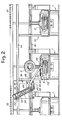
- a head 22 is mounted according to a vertical articulation axis 20, which head can swing - together with all is connected thereto - around said vertical axis in a horizontal plane, for example, between the position shown by a continuous line and the position 22X shown by a dotted line in Fig. 1.
- the head 22 bears an axis 24 being inclined respect to the horizontal and skew respect to the vertical axis 20; around the inclined axis 24 a beam 26 may rotate, in all the positions that can be reached by head 22; from the position shown by continuous line in Figs. 2 and 3, the beam 26 may reach other positions like the one indicated by 26X.
- an articulation axis 28 is formed, being advantageously parallel to the articulation axis 24, to articulate a second head 30.
- Heads 22 and 30 are kinematically connected - for example through a chain system 32 - in order to remain substantially parallel between them during the angular excursions of beam 26; anyway, it is not excluded that some changes may occur in the arrangement of the two heads 22 and 30, connected with the angular excursion of the beam 26.
- the second head 30 carries an articulated end arm 34 especially shaped to be operated by a cam system to be described below.
- the actuating system of beam 26 may consist of a cylinder-piston system 36, combined with chains 32 for the actuation of the beam through the reaction of the chain wheels carried by axis 24.
- the head 22 may be operated by a motor system 40 which reacts on the carriage 18.
- the end arm 24 is articulated at 42 with a connecting rod 44 being articulated at 46 with the head 30; a stylus, summarily illustrated in 48 cooperates with a cam profile (not shown) carried by head 30 in order to obtain a predetermined law of movement of the arm 34 when the articulation 42 is moved with the freedom degree allowed by the connecting rod 44.
- a cylinder-piston operating system 50 causes, by reacting on head 30, the movements of articulation 42 around the articulation 46 and thus the movements of the end arm 34 according to the law imposed by the above mentioned cam profile.
- a system to pick up a tyre is provided, generally indicated by 52 and capable to engage the bead or rim of the tyre to be handled in a horizontal arrangement for example, and besides, to move a regenerated tyre CR from the open mold, which has vulcanized it, on to the conveyor 12.
- the carriage 18 is brought, for example, to the position shown in Fig. 1, and the articulated arm made up of the components 20, 22, 24, 26, 28, 30, 34 is lowered to the position shown in Figs. 1 to 3 and is able to pick up the tyre CR since the cover is lifted; the cover begins to be raised in an approximately vertical direction and then is shifted as shown in Fig.
- the program controlling the articulated arm causes the same arm displacement from the position 26Z, 30Z, 34Z (Fig. 3) as far as the lowered and rotated position shown with 22X, 26X, 30X, 34X (Fig. 1), where the drawing system 52 is able to engage a tyre to be worked CL, for its transfer from a position where it is properly presented as far as the open mold of the machine, from which the retreaded tyre CR has been just before drawn in the above mentioned way.
- the articulated arm is operated by the program to raise the tyre CL, transfer it along the trajectory TL (Fig. 1) and lay it in the mold ready for its reception.
- the loading operation of a tyre CL may be carried out not immediately after a retreaded tyre CR has been drawn.
- the machine After positioning a tyre CL in the open mold, the machine is operated for closing the mold and for the vulcanizing cycle, the articulated arm being moved away in time in order not to interfere with the cover 5 running through its closing trajectory.
- the carriage 18 is in time brought again in operative position respect to the various machines 1, whenever a machine has completed its own vulcanizing cycle, with an adequate and possible phase difference respect to the cycles of the other machines.
- Each machine 1 is associated with a supplying, storing and feeding group partially shown in Fig. 1 and better shown in Figs. 4 to 6.
- Each storing and feeding group is generally indicated by 60 and comprises a framework 62 supporting a chain conveyor 64 driven around end axes 66 and 68 and also advantageously supported by intermediate guide means, developed as bearing rolls 70 and possible auxiliary rails.
- the conveyor 64 has seats 72 for tyres C, which are placed on the conveyor 64 in the seats provided along the conveyor upper branch, to make up a storing reservoir for tyres of the same type to be fed to a same machine.
- Each of the seats 72 is made up of a pair of appendixes singularly combined to the chains of the conveyor 64, thereby, along the driving wheels and, in particular, along the one around the axis 66 reached by the conveyor upper branch, the appendixes progressively and independently tilts as shown in 72X in Figs. 4 and 5; accordingly, a tyre C reaching the position C1 is no longer firmly held by the appendixes forming the seat for the tyre in position C1.
- a drive system 80 can move the equipment 76, 78 around the axis 74, from the position shown by continuous line up to the position 76X, 78X and vice versa.
- said equipment In the position 76X, 78X, said equipment has the plate 78 in such a position as to make contact with the tyre that reaches position C1.
- Plate 78 presents slots, that is, notches 78A, which permit the passage of the appendixes of seats 72 when they tilt, as indicated by 72X, around the driving wheel on the axis 66.
- the plate 78 presents also a pair of small pillars 78B, which are located immediately below the tyre in the position C1 when the plate 78 is in the position 78X and the tyre approaches the position C1.
- the tyre in the position C1 can be picked up by the equipment 76, 78 when the tyre in position C1 approaches the plate 78X and this is moved according to the arrow fx from the position 76X, 78X up to the position shown by continuous line, with the plate 78 being horizontal.
- the tyre which has reached the position C1 is thus brought in the horizontal position CL to be picked up and worked.
- the tyre in position C1 must be centered so as to have its own axis in an exactly defined position to consent the drawing of same tyre by the articulated arm 22, 26, 30, 34. This occurs automatically, with pillars 78B picking up the plate 78 only when tyres are present having the maximum diameter which has been devised when designing the group 60.
- tyres having lower diameter are to be worked, they do not result automatically centered; and, anyway, it is always advisable to provide for an accurate centering of the tyre in the position CL on the horizontal plate 78.
- a centering device is provided, as can be better seen in Figs. 4 and 6, which acts on the lower rim or bead of the tyre in position CL.
- This device comprises a set of centering fingers 84 being articulated at 86 below the plate 78 suitably centrally open; fingers 84 - from a position (shown in dotted line in Fig. 6) where they are lowered and brought near the centre of plate 78- may be lifted and radially displaced in centrifugal direction by a sole and underlying cylinder -piston driving system 88, whose movable head 88A drives the single fingers 84 through small connecting rods 90.
- a tyre in position CL is automatically centered by the fingers 84 which have been raised and spread apart simultaneously and symmetrically; this is possible for a certain range of diameters of the inner rim belonging to tyres of different type.
- a tyre from the storage built up by the conveyor of group 60 may be accurately positioned in a horizontal arrangement, as shown in CL, to be drawn, as above mentioned, by the articulated arm, as previously indicated.
Landscapes
- Engineering & Computer Science (AREA)
- Mechanical Engineering (AREA)
- Moulds For Moulding Plastics Or The Like (AREA)
- Heating, Cooling, Or Curing Plastics Or The Like In General (AREA)
- Tyre Moulding (AREA)
Claims (5)
Applications Claiming Priority (2)
| Application Number | Priority Date | Filing Date | Title |
|---|---|---|---|
| IT09349/84A IT1198794B (it) | 1984-02-29 | 1984-02-29 | Attrezzatura di movimentazione dei copertoni pneumatici verso e da una macchina vulcanizzatrice |
| IT934984 | 1984-02-29 |
Publications (3)
| Publication Number | Publication Date |
|---|---|
| EP0154612A2 EP0154612A2 (de) | 1985-09-11 |
| EP0154612A3 EP0154612A3 (en) | 1988-03-16 |
| EP0154612B1 true EP0154612B1 (de) | 1990-08-01 |
Family
ID=11128812
Family Applications (1)
| Application Number | Title | Priority Date | Filing Date |
|---|---|---|---|
| EP85830043A Expired EP0154612B1 (de) | 1984-02-29 | 1985-02-25 | Vorrichtung zur Ein- und Ausgabe von Reifen bei einer Vulkanisiereinrichtung |
Country Status (6)
| Country | Link |
|---|---|
| US (1) | US4585405A (de) |
| EP (1) | EP0154612B1 (de) |
| JP (1) | JPS60222209A (de) |
| BR (1) | BR8500896A (de) |
| DE (1) | DE3578925D1 (de) |
| IT (1) | IT1198794B (de) |
Families Citing this family (15)
| Publication number | Priority date | Publication date | Assignee | Title |
|---|---|---|---|---|
| DE3925859C2 (de) * | 1989-08-04 | 1999-03-11 | Stahl R Blasformtechnik | Blasformmaschine |
| IT1240507B (it) * | 1990-07-27 | 1993-12-17 | Firestone Int Dev Spa | Dispositivo caricatore-scaricatore di pneumatici di veicoli |
| US5820885A (en) * | 1993-09-14 | 1998-10-13 | Mitsubishi, Jukogyo Kabushiki Kaisha | Tire vulcanizing system |
| JPH07117055A (ja) * | 1993-10-21 | 1995-05-09 | Kobe Steel Ltd | タイヤ加硫機に対するローダシステム及びローダ方法 |
| JPH07227850A (ja) * | 1994-02-15 | 1995-08-29 | Kobe Steel Ltd | タイヤ加硫機工場におけるグリーンタイヤ搬送システム |
| JPH0857858A (ja) * | 1994-08-25 | 1996-03-05 | Kobe Steel Ltd | タイヤ加硫システム |
| EP0709179B1 (de) * | 1994-10-31 | 2002-04-03 | Mitsubishi Jukogyo Kabushiki Kaisha | Reifenvulkanisiervorrichtung |
| JP3245011B2 (ja) * | 1995-07-20 | 2002-01-07 | 三菱重工業株式会社 | タイヤ加硫設備の生タイヤ供給設備 |
| FR2737678A1 (fr) * | 1995-08-08 | 1997-02-14 | Sedepro | Manipulation de pneumatiques vulcanises, en particulier refroidissement de ceux-ci |
| JP3637156B2 (ja) * | 1996-07-29 | 2005-04-13 | 三菱重工業株式会社 | タイヤ加硫機 |
| KR100263815B1 (ko) * | 1998-09-23 | 2000-08-16 | 정성수 | 재생 타이어의 제조장치 |
| JP4917837B2 (ja) * | 2006-05-31 | 2012-04-18 | 住友ゴム工業株式会社 | タイヤ加硫装置 |
| CN103523510B (zh) * | 2012-07-04 | 2016-02-03 | 青岛科捷物流科技有限公司 | 一种轮胎自动装卸方法 |
| DE112015005209A5 (de) | 2014-11-18 | 2017-08-10 | Harburg-Freudenberger Maschinenbau Gmbh | Vorrichtung und Transporteinrichtung zur Handhabung von Reifenrohlingen |
| EP3792048B1 (de) * | 2019-09-16 | 2023-05-24 | Desmasa, S.L. | Handhabungskopf für rohreifenlaufflächen |
Family Cites Families (17)
| Publication number | Priority date | Publication date | Assignee | Title |
|---|---|---|---|---|
| US1326874A (en) * | 1919-12-30 | macbeth and e | ||
| US2323767A (en) * | 1941-03-19 | 1943-07-06 | Jr John Hays Hammond | Automatic ignition and gas shutoff mechanism |
| US2802586A (en) * | 1954-08-26 | 1957-08-13 | Bliss E W Co | Coil transfer mechanism |
| FR1136039A (fr) * | 1955-09-27 | 1957-05-07 | Schwermaschb Ernst Thalmann Ma | Appareil roulant pour l'ouverture et la fermeture de moules chauffants pour bandages pneumatiques |
| US2923527A (en) * | 1956-07-02 | 1960-02-02 | Super Mold Corp | Tire spreader |
| US3033387A (en) * | 1959-06-18 | 1962-05-08 | Nat Equip Corp | Article transferring apparatus |
| US3137032A (en) * | 1960-03-29 | 1964-06-16 | Donald M Macmillan | Roll top matrix loader |
| US3091802A (en) * | 1961-06-05 | 1963-06-04 | Rawls Brothers Company | Multiple pneumatic tire retreading station |
| US3130446A (en) * | 1961-07-27 | 1964-04-28 | Super Mold Corp | Tire mold loader |
| US3585679A (en) * | 1963-04-11 | 1971-06-22 | Macmillan Mold Co Inc | Mold loader |
| US3550196A (en) * | 1967-01-30 | 1970-12-29 | Nrm Corp | Tire vulcanizing apparatus |
| SU502763A1 (ru) * | 1971-10-07 | 1976-02-15 | Невинномысский Шиноремонтный Завод | Подвижный перезар дчик дл обслуживани пресс-форм дл вулканизации покрышек пневматических шин |
| US3988077A (en) * | 1975-03-04 | 1976-10-26 | Alexei Mikhailovich Naratov | Pneumatic tire vulcanizing apparatus |
| US4088524A (en) * | 1976-04-14 | 1978-05-09 | Taylor Don A | Method and apparatus for continuously applying tread material to tire casings and curing the same |
| IT1064031B (it) * | 1976-11-15 | 1985-02-18 | Pirelli | Dispositivo per il centraggio reciproco di elementi meccanici relativamente spostabili,particolarmente per l'impiego su presse di vulcanizzazione per pneumatici |
| US4236883A (en) * | 1979-07-05 | 1980-12-02 | Nrm Corporation | Tire press |
| JPS597032A (ja) * | 1982-07-06 | 1984-01-14 | Mitsubishi Heavy Ind Ltd | 生タイヤの供給装置 |
-
1984
- 1984-02-29 IT IT09349/84A patent/IT1198794B/it active
-
1985
- 1985-02-25 EP EP85830043A patent/EP0154612B1/de not_active Expired
- 1985-02-25 DE DE8585830043T patent/DE3578925D1/de not_active Expired - Lifetime
- 1985-02-27 US US06/706,024 patent/US4585405A/en not_active Expired - Fee Related
- 1985-02-28 BR BR8500896A patent/BR8500896A/pt unknown
- 1985-02-28 JP JP60037725A patent/JPS60222209A/ja active Pending
Also Published As
| Publication number | Publication date |
|---|---|
| US4585405A (en) | 1986-04-29 |
| EP0154612A3 (en) | 1988-03-16 |
| DE3578925D1 (de) | 1990-09-06 |
| BR8500896A (pt) | 1985-10-22 |
| IT8409349A0 (it) | 1984-02-29 |
| IT1198794B (it) | 1988-12-21 |
| EP0154612A2 (de) | 1985-09-11 |
| JPS60222209A (ja) | 1985-11-06 |
Similar Documents
| Publication | Publication Date | Title |
|---|---|---|
| US4585405A (en) | Apparatus for handling tires to and from a vulcanizing machine | |
| CN101905527B (zh) | 吹制机和自动更换器 | |
| US20250018752A1 (en) | Method for assembling a pneumatic tyre on a wheel rim | |
| US4197065A (en) | System for feeding raw elastomer products to vulcanizing autoclaves | |
| US5746964A (en) | Loading system and method for a tire vulcanizing machine | |
| JP4204122B2 (ja) | 環状部材のセンタリング装置 | |
| CN111266860B (zh) | 一种汽车玩具智能组装协作机器人 | |
| EP0289469B1 (de) | Reifenvulkanisierpresse mit Vorrichtung zum Laden und Entladen der Reifen | |
| CN207362051U (zh) | 3d热弯机的上下料系统 | |
| CA1326247C (en) | Roll wrapping head storage and delivery apparatus and method | |
| US4462776A (en) | Tire withdrawal arrangement | |
| CN218344652U (zh) | 镜片模具制模输送机 | |
| CN116653303A (zh) | 塑料桶提手自动组装设备 | |
| US4970888A (en) | Method of changing workpiece holders for press machine | |
| US4866974A (en) | Method of changing die assemblies for press machine | |
| CN220993463U (zh) | 全自动高效密封圈组装装置 | |
| CN212860194U (zh) | 一种注塑上料机 | |
| CN218751554U (zh) | 一种固化剂自动灌装设备 | |
| US6051098A (en) | Keyboard etching apparatus | |
| KR102530302B1 (ko) | Cnc선반용 소재 적재장치 | |
| US4830692A (en) | Method and device for automatic assembly of laminated panes | |
| CN210236302U (zh) | 一种套标机的上料装置 | |
| CN111620098B (zh) | 镜片自动整理机 | |
| JP2698032B2 (ja) | 台タイヤの自動投入・取り出し方法及びその装置 | |
| CN114799859A (zh) | 无线充电环形磁体装配装置 |
Legal Events
| Date | Code | Title | Description |
|---|---|---|---|
| PUAI | Public reference made under article 153(3) epc to a published international application that has entered the european phase |
Free format text: ORIGINAL CODE: 0009012 |
|
| AK | Designated contracting states |
Designated state(s): DE FR GB SE |
|
| PUAL | Search report despatched |
Free format text: ORIGINAL CODE: 0009013 |
|
| AK | Designated contracting states |
Kind code of ref document: A3 Designated state(s): DE FR GB SE |
|
| 17P | Request for examination filed |
Effective date: 19880603 |
|
| 17Q | First examination report despatched |
Effective date: 19890424 |
|
| GRAA | (expected) grant |
Free format text: ORIGINAL CODE: 0009210 |
|
| AK | Designated contracting states |
Kind code of ref document: B1 Designated state(s): DE FR GB SE |
|
| PG25 | Lapsed in a contracting state [announced via postgrant information from national office to epo] |
Ref country code: SE Free format text: THE PATENT HAS BEEN ANNULLED BY A DECISION OF A NATIONAL AUTHORITY Effective date: 19900801 Ref country code: FR Effective date: 19900801 |
|
| REF | Corresponds to: |
Ref document number: 3578925 Country of ref document: DE Date of ref document: 19900906 |
|
| EN | Fr: translation not filed | ||
| PGFP | Annual fee paid to national office [announced via postgrant information from national office to epo] |
Ref country code: GB Payment date: 19910215 Year of fee payment: 7 |
|
| PGFP | Annual fee paid to national office [announced via postgrant information from national office to epo] |
Ref country code: DE Payment date: 19910423 Year of fee payment: 7 |
|
| PLBE | No opposition filed within time limit |
Free format text: ORIGINAL CODE: 0009261 |
|
| STAA | Information on the status of an ep patent application or granted ep patent |
Free format text: STATUS: NO OPPOSITION FILED WITHIN TIME LIMIT |
|
| 26N | No opposition filed | ||
| PG25 | Lapsed in a contracting state [announced via postgrant information from national office to epo] |
Ref country code: GB Effective date: 19920225 |
|
| GBPC | Gb: european patent ceased through non-payment of renewal fee | ||
| PG25 | Lapsed in a contracting state [announced via postgrant information from national office to epo] |
Ref country code: DE Effective date: 19921103 |