EP0154654A1 - Dispositif de detection de la position du rotor d'un moteur - Google Patents
Dispositif de detection de la position du rotor d'un moteur Download PDFInfo
- Publication number
- EP0154654A1 EP0154654A1 EP83903309A EP83903309A EP0154654A1 EP 0154654 A1 EP0154654 A1 EP 0154654A1 EP 83903309 A EP83903309 A EP 83903309A EP 83903309 A EP83903309 A EP 83903309A EP 0154654 A1 EP0154654 A1 EP 0154654A1
- Authority
- EP
- European Patent Office
- Prior art keywords
- rotor
- phase
- pulses
- pulse
- code
- Prior art date
- Legal status (The legal status is an assumption and is not a legal conclusion. Google has not performed a legal analysis and makes no representation as to the accuracy of the status listed.)
- Granted
Links
- 238000001514 detection method Methods 0.000 claims abstract 3
- 230000007704 transition Effects 0.000 claims description 8
- 230000008859 change Effects 0.000 abstract description 7
- 230000001360 synchronised effect Effects 0.000 description 17
- 238000010586 diagram Methods 0.000 description 9
- 238000010276 construction Methods 0.000 description 7
- 238000006243 chemical reaction Methods 0.000 description 3
- 230000004044 response Effects 0.000 description 3
- 238000004804 winding Methods 0.000 description 3
- GPDHNZNLPKYHCN-DZOOLQPHSA-N [[(z)-(1-cyano-2-ethoxy-2-oxoethylidene)amino]oxy-morpholin-4-ylmethylidene]-dimethylazanium;hexafluorophosphate Chemical compound F[P-](F)(F)(F)(F)F.CCOC(=O)C(\C#N)=N/OC(=[N+](C)C)N1CCOCC1 GPDHNZNLPKYHCN-DZOOLQPHSA-N 0.000 description 2
- 230000009471 action Effects 0.000 description 2
- 230000001419 dependent effect Effects 0.000 description 2
- 230000004907 flux Effects 0.000 description 2
- 238000000034 method Methods 0.000 description 2
- 230000004048 modification Effects 0.000 description 2
- 238000012986 modification Methods 0.000 description 2
- 102100031033 CCR4-NOT transcription complex subunit 3 Human genes 0.000 description 1
- 101000919663 Homo sapiens CCR4-NOT transcription complex subunit 3 Proteins 0.000 description 1
- 230000007423 decrease Effects 0.000 description 1
- 230000003111 delayed effect Effects 0.000 description 1
- 230000010354 integration Effects 0.000 description 1
Images



Classifications
-
- G—PHYSICS
- G01—MEASURING; TESTING
- G01D—MEASURING NOT SPECIALLY ADAPTED FOR A SPECIFIC VARIABLE; ARRANGEMENTS FOR MEASURING TWO OR MORE VARIABLES NOT COVERED IN A SINGLE OTHER SUBCLASS; TARIFF METERING APPARATUS; MEASURING OR TESTING NOT OTHERWISE PROVIDED FOR
- G01D5/00—Mechanical means for transferring the output of a sensing member; Means for converting the output of a sensing member to another variable where the form or nature of the sensing member does not constrain the means for converting; Transducers not specially adapted for a specific variable
- G01D5/12—Mechanical means for transferring the output of a sensing member; Means for converting the output of a sensing member to another variable where the form or nature of the sensing member does not constrain the means for converting; Transducers not specially adapted for a specific variable using electric or magnetic means
- G01D5/244—Mechanical means for transferring the output of a sensing member; Means for converting the output of a sensing member to another variable where the form or nature of the sensing member does not constrain the means for converting; Transducers not specially adapted for a specific variable using electric or magnetic means influencing characteristics of pulses or pulse trains; generating pulses or pulse trains
- G01D5/24404—Interpolation using high frequency signals
-
- G—PHYSICS
- G01—MEASURING; TESTING
- G01D—MEASURING NOT SPECIALLY ADAPTED FOR A SPECIFIC VARIABLE; ARRANGEMENTS FOR MEASURING TWO OR MORE VARIABLES NOT COVERED IN A SINGLE OTHER SUBCLASS; TARIFF METERING APPARATUS; MEASURING OR TESTING NOT OTHERWISE PROVIDED FOR
- G01D5/00—Mechanical means for transferring the output of a sensing member; Means for converting the output of a sensing member to another variable where the form or nature of the sensing member does not constrain the means for converting; Transducers not specially adapted for a specific variable
- G01D5/12—Mechanical means for transferring the output of a sensing member; Means for converting the output of a sensing member to another variable where the form or nature of the sensing member does not constrain the means for converting; Transducers not specially adapted for a specific variable using electric or magnetic means
- G01D5/244—Mechanical means for transferring the output of a sensing member; Means for converting the output of a sensing member to another variable where the form or nature of the sensing member does not constrain the means for converting; Transducers not specially adapted for a specific variable using electric or magnetic means influencing characteristics of pulses or pulse trains; generating pulses or pulse trains
- G01D5/245—Mechanical means for transferring the output of a sensing member; Means for converting the output of a sensing member to another variable where the form or nature of the sensing member does not constrain the means for converting; Transducers not specially adapted for a specific variable using electric or magnetic means influencing characteristics of pulses or pulse trains; generating pulses or pulse trains using a variable number of pulses in a train
- G01D5/2454—Encoders incorporating incremental and absolute signals
- G01D5/2455—Encoders incorporating incremental and absolute signals with incremental and absolute tracks on the same encoder
-
- H—ELECTRICITY
- H03—ELECTRONIC CIRCUITRY
- H03M—CODING; DECODING; CODE CONVERSION IN GENERAL
- H03M1/00—Analogue/digital conversion; Digital/analogue conversion
- H03M1/12—Analogue/digital converters
- H03M1/14—Conversion in steps with each step involving the same or a different conversion means and delivering more than one bit
- H03M1/143—Conversion in steps with each step involving the same or a different conversion means and delivering more than one bit in pattern-reading type converters, e.g. having both absolute and incremental tracks on one disc or strip
-
- H—ELECTRICITY
- H03—ELECTRONIC CIRCUITRY
- H03M—CODING; DECODING; CODE CONVERSION IN GENERAL
- H03M1/00—Analogue/digital conversion; Digital/analogue conversion
- H03M1/12—Analogue/digital converters
- H03M1/22—Analogue/digital converters pattern-reading type
- H03M1/24—Analogue/digital converters pattern-reading type using relatively movable reader and disc or strip
- H03M1/26—Analogue/digital converters pattern-reading type using relatively movable reader and disc or strip with weighted coding, i.e. the weight given to a digit depends on the position of the digit within the block or code word, e.g. there is a given radix and the weights are powers of this radix
-
- H—ELECTRICITY
- H03—ELECTRONIC CIRCUITRY
- H03M—CODING; DECODING; CODE CONVERSION IN GENERAL
- H03M1/00—Analogue/digital conversion; Digital/analogue conversion
- H03M1/12—Analogue/digital converters
- H03M1/22—Analogue/digital converters pattern-reading type
- H03M1/24—Analogue/digital converters pattern-reading type using relatively movable reader and disc or strip
- H03M1/28—Analogue/digital converters pattern-reading type using relatively movable reader and disc or strip with non-weighted coding
- H03M1/30—Analogue/digital converters pattern-reading type using relatively movable reader and disc or strip with non-weighted coding incremental
- H03M1/303—Circuits or methods for processing the quadrature signals
Definitions
- This invention relates to a rotor position sensing apparatus for motors for sensing the rotational position of a motor such as a synchronous motor. More particularly, the invention relates to a rotor position sensing apparatus for motors wherein a fine position code is capable of being generated be performing an interpolation between position codes from a sensor provided on a rotor.
- a rotating field-type synchronous motor which is composed of an armature serving as a stator and a field pole serving as a rotor, is operable to generate a rotating field by application of a three-phase current to the stator windings (armature windings), with the field pole being pulled by the rotating field so as to rotate at the same velocity as the rotating field.
- torque generation is controlled in a manner equivalent to that of a DC motor if the armature current and induced voltage are controlled to have the same phase (i.e., if control is effected in such a manner that the main flux and armature current are rendered mutually perpendicular).
- the position of the field pole i.e., the phase of the main flux, which is displaced from the phase of the induced voltage by 90 0
- the current command having a phase corresponding to the position
- a widely adopted arrangement has a pulse coder provided on the rotary shaft of the field pole (rotor).
- the pulse coder produces a position code corresponding to the rotational position of the rotor and thus allows the rotational position of the rotor to be sensed.
- the pulse coder is composed of a rotary disk having position codes disposed radially of the disk at predetermined angles, and a sensor for reading the position codes.
- the number of position codes capable of being disposed along the circumference of the coder is limited by resolution, with the number being several hundred at most even if a high-resolution Gray code is used as the position code. The position sensing precision is therefore less than satisfactory, making it difficult to carry out fine control.
- an object of the present invention is to provide a rotor position sensing apparatus for motors which, irrespective of a limitation imposed on a number of position codes by the resolution of a sensor for sensing the rotational position of a rotor, readily enables generation of fine position signals surpassing the number of position codes of the sensor.
- a sensor generates a coarse position code which corresponds to the rotational position of a rotor of a motor, as well as fine rotation pulses each of which is issued whenever the rotor rotates through a predetermined angle.
- the rotation pulses are counted by a counter.
- the rotational position of the rotor is indicated by the coarse position code and the value counted by the counter. According to the invention, a precise rotor position is capable of being indicated even when the position code is coarse, thereby enabling a motor to be controlled in accurate fashion.
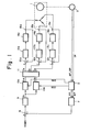
- Fig. 1 is a block diagram of an embodiment of the present invention
- Figs. 2 and 3 are views illustrating the construction of a pulse encoder shown in the arrangement of Fig. 1
- Fig. 4 is a view showing the construction of a two phase - three phase converting circuit in the arrangement of Fig. 1
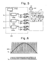
- Fig. 5 is a view showing the construction of a pulse-width modulatorinverter circuit in the arrangement of Fig. 1
- Fig. 6 is a waveform diagram for describing a pulse-width modulation operation performed in Fig. 5
- Fig. 7 is a detailed block diagram of a rotor position sensing apparatus according to the present invention
- Fig. 8 is a waveform diagram for describing the operation of principal portions of Fig. 7, and
- Fig. 9 is a waveform diagram for describing a sine wave generating operation according to the present invention.
- Fig. 1 is a block diagram showing an embodiment of the present invention in its entirety.
- the pulse encoder 2 includes a code disk 23 provided on a rotary shaft 20 which is directly connected to the shaft of the synchronous motor 1, a light-emitting element 22 such as a light-emitting diode for reading a position signal from the code disk 23, a light-receiving element 21 such as a photodiode, the elements 21, 22 being disposed so as to face each other with the code disk 23 interposed therebetween, and an output circuit 24.
- an A-phase track a, a B-phase track b, and a code track d comprising four tracks are formed concentrically on the code disk 23. Patterns are formed on the A- and B-phase tracks a, b in such a manner that rotation pulse trains (incremental pulses) displaced in phase from each other bylT/2 will be generated when the code disk rotates.
- the code track d comprises four tracks each of which is formed with a pattern in such a manner that different four-bit position codes (absolute codes) will be generated in correspondence with each angle of rotation of the code disk.
- a Gray code is used for the position codes.
- Numeral 3 denotes a sine wave generating circuit, described below.
- the circuit includes a counter which is set to a position code IP from the pulse encoder 2, and which counts A-phase pulses AP and B-phase pulses BP from the pulse encoder 2 for producing values of sine, cos ⁇ , which are dependent upon the counted value.
- Numeral 7 denotes an F/V converter for converting the pulse rate of a positive pulse train PP or negative pulse train N P from the sine wave generating circuit 3 into a voltage, the output voltage being an actual velocity voltage TSA, which is proportional to the rotational velocity of the synchronous motor 1.
- Numeral 8 denotes an arithmetic circuit for calculating the difference (hereafter referred to as a velocity error) ER between the actual velocity voltage TSA and a velocity command VCMD issued by a velocity command circuit, not shown.
- Numeral 9 designates an error amplifier for amplifying the velocity error ER to produce the amplitude I s of an armature current.
- Numeral 11 denotes a two phase - three phase converting circuit having the circuit construction shown in Fig. 4 for converting the two-phase signal into a three-phase signal. More specifically, the two phase - three phase converting circuit 11 includes two operational amplifiers OA 1 , OA 2 , 10 K ⁇ resistors R 1 through R 4 , a 5.78 K ⁇ resistor R 5 , and a 5 K ⁇ resistor R 6 .
- Numerals 12, 12b, 12c denote arithmetic circuits for obtaining the differences between the commanded currents I u , I v , I w and the actual phase currents. More specifically, these calculate the differences between the current commands I u , I v , I w in the respective phases, and actual phase currents I au , I av , I aw sensed by current transformers 15a, 15b, 15c, respectively.
- Numerals 13a, 13b 13c denote current amplifiers provided in the respective phases for amplifying the current differences in these phases.
- Numerals 14a, 14b, 14c designate pulse-width modulator/inverter circuits. As illustrated in Fig.
- the pulse width modulator/inverter circuits 14a, 14b, 14c each include a sawtooth generating circuit for generating a triangular wave, e.g., a sawtooth signal STS, comparators COM u , COM v , COM w , NOT gates NOT 1 through NOT3, and drivers DV 1 through DV 6 .
- the inverter 14 includes six power transistors Q 1 through Q 6 and six diodes D 1 through D 6 . These construct a pulse-width modulator circuit 140.
- the comparators COM u , COM v , COM w compare the sawtooth signal STS with the amplitudes of the three-phase alternating current signals i u , i v , i w , respectively, and produce a "1" output when i u , i v or i w is greater than the value of STS, or a "0" output when i u , i v or i w is smaller.
- the comparator COM u produces the pulse-width modulated current command i uc shown in Fig. 6. More specifically, pulse-width modulated three-phase current commands i uc , i vc' i wc dependent upon the amplitudes of i , i v , i w are produced.
- a triangular signal in the form of isosceles triangles can be employed instead of the sawtooth signal used for pulse-width modulation.
- the NOT gates NOT 1 through NOT 3 and drivers DV 1 through DV 6 convert the current commands i uc , i vc' i wc into drive signals SQ 1 through SQ 6 to control the on/off action of the power transistors Q 1 through Q 6 constituting the inverter 141.
- Numeral 142 denotes a rectifying circuit for DC current feed
- numerals 15a, 15b, 15c designate current transformers for sensing the phase currents.
- the position code IP from the pulse encoder 2 enters the sine wave generating circuit 3, which converts the code into corresponding values of cos ⁇ , sine and produces output voltages conforming to cos ⁇ , sine.
- the velocity command VCMD is applied to the synchronous motor 1, which is supplied with three-phase alternating current.
- the pulse encoder 2 When the synchronous motor 1 rotates, the pulse encoder 2 generates the A-phase pulses AP and the B-phase pulses BP, depending upon the direction of rotation. These pulses are counted by the counter.
- a sine wave sine and a cosine wave cos9 conforming to both the position code IP and position ⁇ of the rotor are produced.
- an addition input terminal of the arithmetic circuit 8 is supplied with a velocity command VCMD having a predetermined analog value. Since the synchronous motor 1 is rotating at an actual velocity V a ( ⁇ V c ), the F/V converter 7 produces the actual velocity voltage TSA, which is proportional to the actual velocity V a The actual velocity voltage TSA is applied to a subtraction terminal of the arithmetic circuit 8. Accordingly, the arithmetic circuit 8 calculates the velocity error ER, which is the difference between the commanded velocity V c and the actual velocity V a , and applies the error to the error amplifier 9. The error amplifier 9 performs a proportional integration operation expressed by the following equation:
- the two phase - three phase converting circuit 11 then performs the computation indicated by Eq. (1) to produce three-phase current commands I u , I v , I w . These are three-phase current commands the phases of which are the same as those of the induced voltage E o of the synchronous motor 1.
- the arithmetic circuits 12a, 12b, 12c compute the differences between the three-phase current commands I u , I v , I w and the actual phase currents I au , i av , I aw' These differences, namely the three-phase AC signals i u , i v , i w , are amplified and then applied to the respective comparators COM U , COM V , COM W of the pulse-width modulator/inverter circuits 14a, 14b, 14c.
- the comparators COM U , COM V , COM W compare the sawtooth signal STS with the amplitudes of the three-phase AC signals i , i v , i w and produce the pulse-width modulated three-phase current commands i uc , i vc' i wc' whereby the inverter drive signals SQ 1 through SQ 6 are produced via the NOT gates NOT 1 through NOT 3 and drivers DV 1 through DV 6 .
- the inverter drive signals SQ 1 through SQ 6 are applied to the bases of the respective power transistors Q 1 through Q 6 constituting the inverter 141, thereby controlling the on/off action of the power transistors Q, through Q 6 to supply the synchronous motor 1 with three-phase current. Control is thenceforth performed in a similar manner until the synchronous motor 1 eventually rotates at the commanded velocity.
- Fig. 7 is a block diagram of an embodiment of the present invention.
- numeral 30 denotes a quadrupling pulse generating circuit. Using the A- and B-phase rotation pulses AP, BP, the quadrupling pulse generating circuit 30 generates quadrupled positive rotation pulses PP when rotation is in the forward direction, and quadrupled negative rotation pulses NP when rotation is in the reverse direction.
- Numeral 31 denotes a leading edge/trailing edge sensing circuit for sensing the leading edge/trailing edge of each bit of bits C 1 through C 8 of the position code IP, and for producing preset data PD and a preset signal PS for a counter, described below.
- Numeral 32 denotes an up/down counter which is set to the preset data PD in response to the preset signal PS from the leading edge/trailing edge sensing circuit 31, and which counts up the positive rotation pulses PP and counts down the negative rotation pulses NP.
- Numeral 33 denotes a Gray/binary conversion circuit for converting the Gray code of the position code IP (bits C1 through C 8 ) into a binary code.
- Numeral 34 denotes a read-only memory (ROM) which stores the digital values sin ⁇ , cos ⁇ of the sine and cosine waves at respective addresses.
- Numeral 35 denotes a digital/analog (DA) converter for converting the values of sin ⁇ , cos ⁇ from the ROM 34 into analog outputs which are delivered to the multiplier circuits 10a, 10b (Fig. 1), respectively.
- DA digital/analog
- the quadrupling pulse generating circuit 30 is provided with a NOT circuit N1 and flip-flop circuits FF 1 , FF 2 for the A-phase pulses AP, and with a NOT circuit N 2 and flip-flop circuits FF 3 , FF 4 for the B-phase pulses BP. Also provided is a gate group circuit GC for forming the positive rotation pulses PP or reverse rotation pulses from the outputs of the flip-flops FF 1 through FF 4 . This circuit will now be described with reference to the waveform diagram of Fig. 8. If the motor is rotating in the forward direction, the B-phase pulses BP are generated at a 90° phase lag with respect to the A-phase pulses AP.
- the A-phase pulses AP are generated at a 90° phase lag with respect to the B-phase pulses BP. Accordingly, as shown by the waveform diagram for forward rotation in Fig. 8, the Q, Q outputs of the flip-flop circuit FF 1 have the form A l , A 1 shown in the Figure, so that an output is generated in phase with, or opposite in phase to, the A-phase pulses AP. These outputs A 1 , A 1 are delayed by one block by means of the flip-flop circuit FF 2 , emerging as outputs A 2 , A 2 .
- the aforementioned leading edge/trailing edge sensing circuit 31 is provided with NOT circuits N 3 , N 4 , N 5 , N 6 , prestage flip-flop circuits FF 5 , FF 7 , FF 9 , FF 11 and poststage flip-flop circuits FF6, FF 8 , FF10, FF 12 for the bits C 1 , C 2 , C 4 , C 8 of the position code IP.
- These 16 outputs C 81 through C 12 are applied to the gate group circuit GD, which forms the preset data PD and preset signal PS.
- the gate group circuit GD senses the transition points of the position code IP (i.e., the leading edge/trailing edge thereof). Specifically, since the four outputs C 81 through C 82 , C 41 through C 42 . C 21 through C 22 or C 11 through C 12 will have the same phase relationship as the outputs A1 through A 2 of Fig. 8, as mentioned above, the trailing edge of each bit is capable of being sensed by the conditions ( C 81 ⁇ C 82 ), ( C 41 .C 42 ), ( C 21 -C 22 )' ( C 11 .
- each bit is capable of being sensed by the conditions (c 8 1. C 82 ), (C 41' C 42 ) ' (C 21 . C 22 ) ' (C 11 .C 12 ) ' so that it will suffice if four AND gates are provided for detecting these conditions.
- the logical sum of the outputs from these eight AND gates is taken by an OR gate, the output of which is delivered as the preset signal PS.
- the gate group circuit GD also has a circuit for sensing the direction of motor rotation from the aforementioned 16 inputs C 81 through C12, and for producing preset data "0000" as an output in case of forward rotation, and preset data "1111” as an output in case of reverse rotation.
- a change in the Gray code is utilized. Specifically, the Gray code is arranged as shown in the following table:
- the quadrupling pulse generating circuit 30 For forward rotation of the motor, the quadrupling pulse generating circuit 30 generates the positive rotation pulses PP by utilizing the above-described A- and B-phase pulses AP, BP.
- the counter 32 counts up the positive rotation pulses.
- the position code IP is applied to the leading edge/trailing edge sensing circuit 31, which senses the transition points (leading edge/trailing edge) and generates the preset signal PS.
- a forward rotation pulse is produced whenever a transition point occurs, and "0000" is generated as the preset data PD.
- the counter 32 is preset to the preset data PD "0000" whenever a transition point is sensed, and thereafter counts up the positive rotation pulses PP until the next transition point is sensed (i.e., until the preset signal PS is generated).
- the position code IP is converted into a binary position code IP by the Gray/binary conversion circuit 33 and is applied to the ROM 34 as the higher order digit of the address thereof.
- the value counted by the counter 32 is applied to the ROM 34 as the lower order digit of the address.
- the values of sine, cos ⁇ at the corresponding address of the ROM 34 are read from the ROM.
- the number of addresses applied to the ROM 34 is 2 n times the number that would prevail in the case of the position code IP alone (where n is the number of bits possessed by the counter 32).
- n is the number of bits possessed by the counter 32.
- the values of sin ⁇ , cos8 are converted into analog values of sin&, cos ⁇ by the DA converter 35.
- the analog value of sin ⁇ or of cos8 is delivered as an output M having a smooth, sinusoidal waveform, rather than as an output N which has a step-like waveform when the solely the position code IP is used.
- the quadrupling pulse generating circuit 30 If the motor is rotating in the reverse direction, the quadrupling pulse generating circuit 30 generates the negative rotation pulses NP, and the leading edge/trailing edge sensing circuit 31 generates "1111" as the preset data PD whenever the preset signal PS is generated.
- the counter 32 is preset to the preset data PD "llll" whenever the preset signal PS is generated, and thereafter counts down the negative rotation pulses NP until the next preset signal PS is generated.
- the ROM 34 is then addressed in the manner described above with regard to forward rotation, and therefore the description thereof is deleted.
- a counter is provided for counting fine rotation pulses from a sensor, and the rotational position of a rotor is indicated by a rough position code from the sensor and the value counted by the counter.
- the invention is advantageous in that a fine rotor position can be indicated even when the position code is coarse.
- the present invention which makes it possible to produce a number of position codes several score that of the number of actual position codes, is extremely useful for precise control of a motor. Since the foregoing can be achieved purely through circuitry without modification of the conventional sensor, the apparatus is simple in construction and control can be performed with facility.
- the arrangement is such that a fine position code can be generated by performing an interpolation between position codes from a sensor provided on the rotor of a motor, thereby making it possible to provide a precise indication of the position of the motor rotor.
- the motor can be controlled in a precise manner.
- the present invention is therefore well-suited for application to the field of motor control.
Landscapes
- Physics & Mathematics (AREA)
- General Physics & Mathematics (AREA)
- Engineering & Computer Science (AREA)
- Theoretical Computer Science (AREA)
- Control Of Motors That Do Not Use Commutators (AREA)
- Transmission And Conversion Of Sensor Element Output (AREA)
- Measurement Of Length, Angles, Or The Like Using Electric Or Magnetic Means (AREA)
Abstract
Applications Claiming Priority (2)
| Application Number | Priority Date | Filing Date | Title |
|---|---|---|---|
| JP187939/82 | 1982-10-26 | ||
| JP57187939A JPS5980186A (ja) | 1982-10-26 | 1982-10-26 | モ−タのロ−タ位置検出回路 |
Publications (3)
| Publication Number | Publication Date |
|---|---|
| EP0154654A1 true EP0154654A1 (fr) | 1985-09-18 |
| EP0154654A4 EP0154654A4 (fr) | 1988-08-23 |
| EP0154654B1 EP0154654B1 (fr) | 1991-01-16 |
Family
ID=16214816
Family Applications (1)
| Application Number | Title | Priority Date | Filing Date |
|---|---|---|---|
| EP83903309A Expired EP0154654B1 (fr) | 1982-10-26 | 1983-10-26 | Dispositif de detection de la position du rotor d'un moteur |
Country Status (5)
| Country | Link |
|---|---|
| US (1) | US4623831A (fr) |
| EP (1) | EP0154654B1 (fr) |
| JP (1) | JPS5980186A (fr) |
| DE (1) | DE3382126D1 (fr) |
| WO (1) | WO1984001821A1 (fr) |
Cited By (12)
| Publication number | Priority date | Publication date | Assignee | Title |
|---|---|---|---|---|
| EP0333928A3 (fr) * | 1988-03-22 | 1991-11-21 | EGM Entwicklungsgesellschaft für Montagetechnik GmbH | Méthode et dispositif pour mesure indirecte de position |
| WO1992011452A3 (fr) * | 1990-12-07 | 1992-08-06 | Vogt Electronic Ag | Circuit de commande electronique de machines a combustion interne |
| EP0502534A3 (en) * | 1991-03-06 | 1993-06-23 | Hitachi, Ltd. | Encoder |
| EP0602657A3 (en) * | 1992-12-18 | 1995-11-29 | Nitto Kohki Co | Safety operation system for manipulator. |
| WO1996023198A1 (fr) * | 1995-01-25 | 1996-08-01 | Bourns, Inc. | Codeur a position numerique absolue |
| EP0732567A1 (fr) * | 1995-03-11 | 1996-09-18 | Dr. Johannes Heidenhain GmbH | Appareil de mesure de position |
| US5687103A (en) * | 1994-10-13 | 1997-11-11 | Johannes Heidenhain Gmbh | Position measuring device |
| US5739775A (en) * | 1993-07-22 | 1998-04-14 | Bourns, Inc. | Digital input and control device |
| US5880683A (en) * | 1993-07-22 | 1999-03-09 | Bourns, Inc. | Absolute digital position encoder |
| WO2003044465A3 (fr) * | 2001-11-16 | 2003-11-20 | Trw Lucas Varity Electric | Detecteur de positions angulaires |
| US9399723B2 (en) | 2011-08-10 | 2016-07-26 | Tesa Se | Electrically conductive adhesive compound and adhesive tape |
| US9593264B2 (en) | 2011-08-10 | 2017-03-14 | Tesa Se | Electrically conductive heat-activated adhesive compound |
Families Citing this family (14)
| Publication number | Priority date | Publication date | Assignee | Title |
|---|---|---|---|---|
| JPS6126491A (ja) * | 1984-07-16 | 1986-02-05 | Fuji Electric Co Ltd | 無整流子電動機 |
| JPS6315116A (ja) * | 1986-07-07 | 1988-01-22 | Fanuc Ltd | モ−タロ−タ位置検出方法 |
| JPH0823502B2 (ja) * | 1986-11-18 | 1996-03-06 | 株式会社明電舎 | 位置検出装置 |
| JPH04333904A (ja) * | 1991-05-09 | 1992-11-20 | Brother Ind Ltd | サーボモータの制御装置 |
| KR100203063B1 (ko) * | 1992-07-09 | 1999-06-15 | 윤종용 | 엔코더형모터의속도검출장치 |
| US5699058A (en) * | 1994-03-17 | 1997-12-16 | Copal Company Limited | Absolute encoder generating phase-shifted triangular waveforms to produce multi-bit signals |
| US5646496A (en) * | 1994-11-08 | 1997-07-08 | Dana Corporation | Apparatus and method for generating digital position signals for a rotatable shaft |
| US6037735A (en) * | 1999-03-01 | 2000-03-14 | Eastman Kodak Company | Slow-speed servomechanism |
| US6944906B2 (en) | 2002-05-15 | 2005-09-20 | Trico Products Corporation | Direct drive windshield wiper assembly |
| US7676880B2 (en) * | 2002-05-15 | 2010-03-16 | Trico Products Corporation | Direct drive windshield wiper assembly |
| US7015832B2 (en) * | 2004-05-25 | 2006-03-21 | Bei Sensors & Systems Company, Inc. | Pulse width modulation based digital incremental encoder |
| TWI408893B (zh) * | 2008-12-24 | 2013-09-11 | Ind Tech Res Inst | 伺服馬達低速控制方法與裝置 |
| CN103308854A (zh) * | 2012-03-08 | 2013-09-18 | 深圳市蓝韵实业有限公司 | 电机运动故障监控方法及系统 |
| CN102868404A (zh) * | 2012-09-14 | 2013-01-09 | 北京交通大学 | 基于余弦算法和格雷编码的模数转换方法 |
Family Cites Families (16)
| Publication number | Priority date | Publication date | Assignee | Title |
|---|---|---|---|---|
| CH511423A (de) * | 1969-08-05 | 1971-08-15 | Oerlikon Buehrle Ag | Vorrichtung zum Ablesen und Auswerten eines Codeträgers |
| US3824587A (en) | 1972-10-25 | 1974-07-16 | Laitram Corp | Dual mode angle encoder |
| JPS52124352A (en) * | 1976-04-12 | 1977-10-19 | Nippon Chemical Ind | Scale reader |
| US4194184A (en) | 1976-04-30 | 1980-03-18 | Rca Corporation | Bidirectional digital position encoder |
| JPS5333162A (en) * | 1976-09-08 | 1978-03-28 | Nissan Motor | Displacement meter |
| JPS5362354U (fr) * | 1976-10-28 | 1978-05-26 | ||
| US4090116A (en) | 1976-12-10 | 1978-05-16 | General Electric Company | Closed loop digital control system and method for motor control |
| JPS54151263U (fr) * | 1978-04-12 | 1979-10-20 | ||
| DE2921103C2 (de) * | 1979-05-25 | 1986-09-25 | Robert Bosch Gmbh, 7000 Stuttgart | Inkrementaler Drehwinkelgeber |
| DE2948854A1 (de) * | 1979-12-05 | 1981-06-11 | Dr. Johannes Heidenhain Gmbh, 8225 Traunreut | Inkrementales messsystem |
| JPS6031196B2 (ja) | 1979-12-11 | 1985-07-20 | ファナック株式会社 | 誘導電動機の可変速運転装置 |
| GB2076147B (en) * | 1980-05-15 | 1984-07-11 | Ferranti Ltd | Position encoder |
| JPS573582A (en) | 1980-06-05 | 1982-01-09 | Toshiba Corp | Controller for inverter |
| JPS5739312A (en) * | 1980-08-20 | 1982-03-04 | Fanuc Ltd | Pulse encoder device having alarm circuit |
| JPS58157384A (ja) | 1982-03-12 | 1983-09-19 | Fanuc Ltd | 交流モ−タの駆動方式 |
| GB2121252A (en) * | 1982-05-18 | 1983-12-14 | Marconi Co Ltd | Apparatus for indicating the position of a member |
-
1982
- 1982-10-26 JP JP57187939A patent/JPS5980186A/ja active Pending
-
1983
- 1983-10-26 WO PCT/JP1983/000380 patent/WO1984001821A1/fr not_active Ceased
- 1983-10-26 US US06/650,721 patent/US4623831A/en not_active Expired - Lifetime
- 1983-10-26 DE DE8383903309T patent/DE3382126D1/de not_active Expired - Lifetime
- 1983-10-26 EP EP83903309A patent/EP0154654B1/fr not_active Expired
Cited By (16)
| Publication number | Priority date | Publication date | Assignee | Title |
|---|---|---|---|---|
| EP0333928A3 (fr) * | 1988-03-22 | 1991-11-21 | EGM Entwicklungsgesellschaft für Montagetechnik GmbH | Méthode et dispositif pour mesure indirecte de position |
| WO1992011452A3 (fr) * | 1990-12-07 | 1992-08-06 | Vogt Electronic Ag | Circuit de commande electronique de machines a combustion interne |
| EP0490088A3 (en) * | 1990-12-07 | 1992-09-02 | Vogt Electronic Aktiengesellschaft | Circuit for the electronic control of an internal combustion engine |
| EP0502534A3 (en) * | 1991-03-06 | 1993-06-23 | Hitachi, Ltd. | Encoder |
| US5530331A (en) * | 1991-03-06 | 1996-06-25 | Hitachi, Ltd. | Encoder, servo system and industrial robot |
| EP0602657A3 (en) * | 1992-12-18 | 1995-11-29 | Nitto Kohki Co | Safety operation system for manipulator. |
| US5739775A (en) * | 1993-07-22 | 1998-04-14 | Bourns, Inc. | Digital input and control device |
| US5880683A (en) * | 1993-07-22 | 1999-03-09 | Bourns, Inc. | Absolute digital position encoder |
| US5751230A (en) * | 1993-07-22 | 1998-05-12 | Bourns, Inc. | Digital input and control device |
| US5687103A (en) * | 1994-10-13 | 1997-11-11 | Johannes Heidenhain Gmbh | Position measuring device |
| WO1996023198A1 (fr) * | 1995-01-25 | 1996-08-01 | Bourns, Inc. | Codeur a position numerique absolue |
| EP0732567A1 (fr) * | 1995-03-11 | 1996-09-18 | Dr. Johannes Heidenhain GmbH | Appareil de mesure de position |
| WO2003044465A3 (fr) * | 2001-11-16 | 2003-11-20 | Trw Lucas Varity Electric | Detecteur de positions angulaires |
| US7022975B2 (en) | 2001-11-16 | 2006-04-04 | Trw Lucasvarity Electric Steering Limited | Angular position sensor |
| US9399723B2 (en) | 2011-08-10 | 2016-07-26 | Tesa Se | Electrically conductive adhesive compound and adhesive tape |
| US9593264B2 (en) | 2011-08-10 | 2017-03-14 | Tesa Se | Electrically conductive heat-activated adhesive compound |
Also Published As
| Publication number | Publication date |
|---|---|
| EP0154654A4 (fr) | 1988-08-23 |
| EP0154654B1 (fr) | 1991-01-16 |
| DE3382126D1 (de) | 1991-02-21 |
| US4623831A (en) | 1986-11-18 |
| WO1984001821A1 (fr) | 1984-05-10 |
| JPS5980186A (ja) | 1984-05-09 |
Similar Documents
| Publication | Publication Date | Title |
|---|---|---|
| EP0154654A1 (fr) | Dispositif de detection de la position du rotor d'un moteur | |
| US4943760A (en) | Control systems for variable reluctance electrical machines | |
| US4228396A (en) | Electronic tachometer and combined brushless motor commutation and tachometer system | |
| US4772815A (en) | Variable refluctance position transducer | |
| GB2145297A (en) | Brushless motor control | |
| JPH04505801A (ja) | レゾルバにより回転数比例電圧を発生するための方法およびこの方法を実施するための回路装置 | |
| JP2572026B2 (ja) | 速度信号発生装置 | |
| US4559485A (en) | Control systems for AC induction motors | |
| KR100355062B1 (ko) | 무브러쉬dc모터의최고속도를최대화하기위한방법및장치 | |
| US4266176A (en) | Induction motor slip frequency controller | |
| CN100511964C (zh) | 马达控制器 | |
| CN206077268U (zh) | 用于速度和位置反馈的正余弦信号处理电路 | |
| CN106357172A (zh) | 用于速度和位置反馈的正余弦信号处理电路 | |
| US4558269A (en) | Induction motor drive apparatus | |
| EP0133580A1 (fr) | Circuit de commande pour moteur synchrone à aimant permanent | |
| JPH10132605A (ja) | 位置検出装置 | |
| JPH0342325Y2 (fr) | ||
| JPS6169386A (ja) | 無整流子電動機駆動装置 | |
| JP2764722B2 (ja) | エンコーダの読取信号の内挿方法 | |
| JPH0449892B2 (fr) | ||
| KR900005762B1 (ko) | 교류 서어보 시스템 | |
| RU2007027C1 (ru) | Преобразователь перемещения в код | |
| IE56498B1 (en) | Control system for improving induction motor transient response by excitation angle control | |
| JPS6130477Y2 (fr) | ||
| KR940008532B1 (ko) | 교류 서보 모터 제어 회로 |
Legal Events
| Date | Code | Title | Description |
|---|---|---|---|
| PUAI | Public reference made under article 153(3) epc to a published international application that has entered the european phase |
Free format text: ORIGINAL CODE: 0009012 |
|
| 17P | Request for examination filed |
Effective date: 19840928 |
|
| AK | Designated contracting states |
Designated state(s): DE FR GB |
|
| A4 | Supplementary search report drawn up and despatched |
Effective date: 19880823 |
|
| 17Q | First examination report despatched |
Effective date: 19890925 |
|
| GRAA | (expected) grant |
Free format text: ORIGINAL CODE: 0009210 |
|
| AK | Designated contracting states |
Kind code of ref document: B1 Designated state(s): DE FR GB |
|
| REF | Corresponds to: |
Ref document number: 3382126 Country of ref document: DE Date of ref document: 19910221 |
|
| ET | Fr: translation filed | ||
| PGFP | Annual fee paid to national office [announced via postgrant information from national office to epo] |
Ref country code: FR Payment date: 19911010 Year of fee payment: 9 |
|
| PGFP | Annual fee paid to national office [announced via postgrant information from national office to epo] |
Ref country code: GB Payment date: 19911015 Year of fee payment: 9 |
|
| PLBE | No opposition filed within time limit |
Free format text: ORIGINAL CODE: 0009261 |
|
| STAA | Information on the status of an ep patent application or granted ep patent |
Free format text: STATUS: NO OPPOSITION FILED WITHIN TIME LIMIT |
|
| 26N | No opposition filed | ||
| PG25 | Lapsed in a contracting state [announced via postgrant information from national office to epo] |
Ref country code: GB Effective date: 19921026 |
|
| GBPC | Gb: european patent ceased through non-payment of renewal fee |
Effective date: 19921026 |
|
| PG25 | Lapsed in a contracting state [announced via postgrant information from national office to epo] |
Ref country code: FR Effective date: 19930630 |
|
| REG | Reference to a national code |
Ref country code: FR Ref legal event code: ST |
|
| PGFP | Annual fee paid to national office [announced via postgrant information from national office to epo] |
Ref country code: DE Payment date: 20021031 Year of fee payment: 20 |