EP0154719A2 - Appareil de commutation - Google Patents
Appareil de commutation Download PDFInfo
- Publication number
- EP0154719A2 EP0154719A2 EP84116256A EP84116256A EP0154719A2 EP 0154719 A2 EP0154719 A2 EP 0154719A2 EP 84116256 A EP84116256 A EP 84116256A EP 84116256 A EP84116256 A EP 84116256A EP 0154719 A2 EP0154719 A2 EP 0154719A2
- Authority
- EP
- European Patent Office
- Prior art keywords
- cooling
- component
- switching device
- spring element
- cooling part
- Prior art date
- Legal status (The legal status is an assumption and is not a legal conclusion. Google has not performed a legal analysis and makes no representation as to the accuracy of the status listed.)
- Granted
Links
- 238000001816 cooling Methods 0.000 claims abstract description 81
- 238000010521 absorption reaction Methods 0.000 abstract description 2
- 238000002347 injection Methods 0.000 abstract 1
- 239000007924 injection Substances 0.000 abstract 1
- 239000004020 conductor Substances 0.000 description 2
- 239000002184 metal Substances 0.000 description 2
- 238000009825 accumulation Methods 0.000 description 1
- 238000011161 development Methods 0.000 description 1
- 230000018109 developmental process Effects 0.000 description 1
- 230000017525 heat dissipation Effects 0.000 description 1
- 238000011031 large-scale manufacturing process Methods 0.000 description 1
- 238000012986 modification Methods 0.000 description 1
- 230000004048 modification Effects 0.000 description 1
Images
Classifications
-
- H—ELECTRICITY
- H05—ELECTRIC TECHNIQUES NOT OTHERWISE PROVIDED FOR
- H05K—PRINTED CIRCUITS; CASINGS OR CONSTRUCTIONAL DETAILS OF ELECTRIC APPARATUS; MANUFACTURE OF ASSEMBLAGES OF ELECTRICAL COMPONENTS
- H05K7/00—Constructional details common to different types of electric apparatus
- H05K7/20—Modifications to facilitate cooling, ventilating, or heating
- H05K7/2039—Modifications to facilitate cooling, ventilating, or heating characterised by the heat transfer by conduction from the heat generating element to a dissipating body
- H05K7/20509—Multiple-component heat spreaders; Multi-component heat-conducting support plates; Multi-component non-closed heat-conducting structures
Definitions
- the invention is based on an electrical switching device according to the preamble of the main claim.
- the known switching device has a cooling angle on which electrical components emitting dissipated heat are fixed in their lateral position by a comb-like fixing part made of insulating plastic and are pressed against the cooling angle by a spring element.
- a comb-like fixing part made of insulating plastic and are pressed against the cooling angle by a spring element.
- the heat dissipation by the cooling part is disadvantageously often not sufficient.
- the electrical switching device with the characterizing features of the main claim has the advantage that even with dissipating heat dissipating electrical components with plastic housing, the briefly occurring high heat loss can be quickly dissipated by increasing the heat capacity of the cooling association additional cooling part, which lies directly on the base plate of the component.
- the additional cooling part is also advantageously held on the fixing part and pressed by the spring element on the base plate.
- Another advantage is that the spring element attached to the first cooling part holds the entire cooling assembly together on the first cooling part.
- the fixing part in such a way that the at least one electrical component cannot move relative to the at least one additional cooling part and thus damage to the plastic housing of the component, for example a transistor, can be prevented by the additional cooling part; that the fixing part is provided with at least one elastic holding section, via which the spring element presses on the additional cooling part, and that the fixing part has latching means with which, on the one hand, the fixing part on the first cooling part and, on the other hand, the spring element can be detachably fastened on the fixing part.
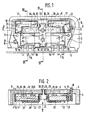
- FIG. 1 shows part of an electrical switching device with a cooling bandage
- FIG. 2 shows a section along the line II-II
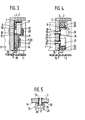
- FIG. 3 shows a section along the line III-III
- FIG. IV shows a section along the line IV-IV in each case in FIG Cooling bandage
- FIG. 5 a modification at V in FIG. 2
- a cooling frame 1 is arranged in an electrical switching device known per se and not shown in detail. On the cooling frame 1 is also known and not shown a conductor tracks and electrical and electronic components carrying circuit board 2 is attached.
- the cooling frame 1 has an area serving as the first cooling part 3 with a cooling level 4. At the cooling level 4 there are two fixing pins 5, on which a heat-conducting insulating film 6 and a fixing part 7 made of insulating plastic are held in their position on the first cooling part 3,
- the fixing part 7 is provided with two locking hooks 8, which protrude through assigned holes 9 in the first cooling part 3 and are locked on the back of the first cooling part 3.
- the fixing part 7 is preassembled on the first cooling part 3 by the locking hooks 8.
- the fixing part 7 is provided with two openings J0 for two electronic components 11 held in position on the first cooling part 3.
- the electronic components 11 are, for example, transistors SOT 93, whose Dissipate heat loss.
- the components 11 with their base plate 12 made of metal lie on the insulating film 6 and thus on the first cooling part 3.
- the openings 10 limiting stops 13 and 14 are formed on the fixing part 7, which stop the components 1.1 in the fixing part 7 from moving on the insulating film 6 and thus prevent on the cooling level 4.
- connection electrodes 15 of the components 11 In the area of the connection electrodes 15 of the components 11, the fixing part 11 is provided with insulating sections 16 encompassing the lower edge of the first cooling part 3. As is known per se, the angled connecting electrodes 15 of the two components 11 are electrically conductively and mechanically connected to associated conductor tracks of the printed circuit board 2.
- the components 11 are pressed by spring force against the first cooling part 3 with the interposition of the insulating film 6. Since in the electrical switching device the electronic components 11 work under conditions that give off high heat loss for a short time, the first cooling part 3 that absorbs and transmits the heat loss is often not sufficient, so that heat accumulation can result in damage to the switching device.
- a second cooling part 17 lies directly on each component 11.
- the second cooling part 17 is a non-insulated metal plate.
- the second cooling part 17 is through limited a stop 21 of the fixing part 7 in its movement to the plastic housing 20 of the component 11 so as not to damage it.
- Elastic flaps 22 are integrally formed on the fixing part 7 and are each pivotably attached to the fixing part 7 by means of a film hinge 23.
- the second cooling parts 17 are pressed by spring force against the base plate 12 of the associated component 11. The spring force acts on the tab 22 pivoted toward the side of the second cooling parts 17 facing away from the base plate 12 and at the same time holds the second cooling parts 17 in the fixing part 7.
- a spring element 24 exerts both the spring force acting directly on the components 11 and on the second cooling parts 17.
- the spring element 24 has a rectangular fastening section 25 with two fastening holes 26.
- Two cranked spring arms 27, 28 are formed on the longitudinal sides of the fastening section 25.
- the spring arms 27 rest against the plastic housing 20 of the assigned component 11, while the narrower spring arms 28, which exert a lower spring force, pivot the tab 22 around the respective film hinge 23 to the assigned second cooling part and into the tab when the spring element 24 is inserted into the fixing part 7 22 concerns.
- the spring element 24 is inserted with its rectangular fastening section 25 into an opening 29 in the fixing part 7.
- Two hollow rivets 30 are inserted into the holes 26, which protrude through bores 3J of the first cooling part 3 and are riveted to the rear of the first cooling part 3.
- a cranked locking projection 32 or 33 is formed on each narrow side of the rectangular fastening section 25 of the spring element 24.
- the locking projections 32 and 33 are pressed behind locking lug pairs 34 and 35 of the fixing part 7.
- the spring element 24 already holds the entire cooling assembly consisting of the first cooling part 3, insulating film 6, fixing part 7, electronic components 11, second cooling parts 17 and spring element 24 before it is attached to the first cooling part 3.
- the briefly occurring high heat loss of the electronic components 11 is now not only given off to the first cooling part 3 with heat transfer via the insulating film 6 and is dissipated from there.
- heat loss is emitted directly to the second cooling part 17 via the base plate 12 of the components 11 and stored there. Since the heat of loss only reaches relatively high values over a short period of time, the heat loss stored in the second cooling part 1-7 is then dissipated via the base plate 12 to the first cooling part 3.
- the capacity for dissipating heat to be dissipated quickly from the electronic component 11 is thus significantly increased in an inventive manner with little means, so that undesired heat build-up can no longer occur at the component 11.
- the second cooling part 17 can also be modified such that it serves for two and more electronic components 11 as a store for dissipated heat to be dissipated.
- the spring element 24 can be designed for pressing on only one or more components 11.
- the spring element 24 By latching on the locking lug pairs 34 and 35 on the fixing part 7, the spring element 24 is also held securely against unequal tilting moment loads.
- the unequal tilting moment loads occur due to the different spring force of the spring arms or spring arm pairs 27 and 28, as well as spring arms 27, 28 formed asymmetrically with respect to the longitudinal axis of the fastening section 25, if the cooling bandage is to be held together for only one electronic component 11.
- FIG. 5 A modified fastening is shown in FIG. 5.
- a pressure plate 36 is arranged on the fastening section 25 of the spring element 24. It is provided with two fastening holes 37 which are aligned with the holes 26 in the spring element 24. Longer hollow rivets 38 are inserted through the pressure plate 36, the spring element 24 and the bores 31 of the first cooling part 3 and riveted to the rear of the first cooling part 3, or the hollow rivets 38 are inserted from the cooling part 3 through the holes and riveted to the pressure plate 36 . It is also possible to detachably fasten the spring element 24 to the first cooling part 3, for example with screws or locking means.
Landscapes
- Physics & Mathematics (AREA)
- Thermal Sciences (AREA)
- Engineering & Computer Science (AREA)
- Microelectronics & Electronic Packaging (AREA)
- Cooling Or The Like Of Electrical Apparatus (AREA)
- Cooling Or The Like Of Semiconductors Or Solid State Devices (AREA)
Applications Claiming Priority (2)
| Application Number | Priority Date | Filing Date | Title |
|---|---|---|---|
| DE3409037 | 1984-03-13 | ||
| DE19843409037 DE3409037A1 (de) | 1984-03-13 | 1984-03-13 | Elektrisches schaltgeraet |
Publications (3)
| Publication Number | Publication Date |
|---|---|
| EP0154719A2 true EP0154719A2 (fr) | 1985-09-18 |
| EP0154719A3 EP0154719A3 (en) | 1986-09-17 |
| EP0154719B1 EP0154719B1 (fr) | 1988-11-23 |
Family
ID=6230256
Family Applications (1)
| Application Number | Title | Priority Date | Filing Date |
|---|---|---|---|
| EP84116256A Expired EP0154719B1 (fr) | 1984-03-13 | 1984-12-22 | Appareil de commutation |
Country Status (4)
| Country | Link |
|---|---|
| US (1) | US4605986A (fr) |
| EP (1) | EP0154719B1 (fr) |
| JP (1) | JPH0680910B2 (fr) |
| DE (2) | DE3409037A1 (fr) |
Cited By (3)
| Publication number | Priority date | Publication date | Assignee | Title |
|---|---|---|---|---|
| GB2189651A (en) * | 1986-04-22 | 1987-10-28 | Weber Srl | A housing and cooling system for a central electronic processing unit of a heat engine |
| WO1988002184A1 (fr) * | 1986-09-10 | 1988-03-24 | Eastman Kodak Company | Support de montage de semi-conducteurs |
| WO2011131686A1 (fr) * | 2010-04-23 | 2011-10-27 | Napatech A/S | Ensemble commandé de manière thermique |
Families Citing this family (31)
| Publication number | Priority date | Publication date | Assignee | Title |
|---|---|---|---|---|
| GB2164213B (en) * | 1984-09-06 | 1988-07-13 | Nec Corp | Structure for connecting leadless chip carrier |
| DE3633625A1 (de) * | 1985-12-04 | 1987-06-11 | Vdo Schindling | Traegerplatte |
| DE3545253A1 (de) * | 1985-12-20 | 1987-06-25 | Philips Patentverwaltung | Einrichtung und verfahren zur montage von waermeerzeugenden bauelementen in einem gehaeuse |
| US4845590A (en) * | 1987-11-02 | 1989-07-04 | Chrysler Motors Corporation | Heat sink for electrical components |
| US4923179A (en) * | 1987-11-02 | 1990-05-08 | Chrysler Corporation | Spring panel heat sink for electrical components |
| US5019942A (en) * | 1987-11-30 | 1991-05-28 | Thermalloy Incorporated | Insulating apparatus for electronic device assemblies |
| US4888637A (en) * | 1988-01-15 | 1989-12-19 | Chrysler Motors Corporation | Multiple semiconductor heat sink/mounting assembly |
| DE3837975A1 (de) * | 1988-11-09 | 1990-05-10 | Telefunken Electronic Gmbh | Elektronisches steuergeraet |
| DE3837974A1 (de) * | 1988-11-09 | 1990-05-10 | Telefunken Electronic Gmbh | Elektronisches steuergeraet |
| US5068764A (en) * | 1990-03-05 | 1991-11-26 | Thermalloy Incorporated | Electronic device package mounting assembly |
| US5060112A (en) * | 1990-04-02 | 1991-10-22 | Cocconi Alan G | Electrical component assembly with heat sink |
| DE4012182A1 (de) * | 1990-04-14 | 1991-10-17 | Bosch Gmbh Robert | Elektrisches schalt- und steuergeraet, insbesondere fuer kraftfahrzeuge |
| US5107330A (en) * | 1990-10-19 | 1992-04-21 | At&T Bell Laboratories | Self-adjusting heat sink design for vlsi packages |
| JPH05121487A (ja) * | 1991-10-26 | 1993-05-18 | Rohm Co Ltd | 半導体装置の実装構造および実装方法 |
| US5289337A (en) * | 1992-02-21 | 1994-02-22 | Intel Corporation | Heatspreader for cavity down multi-chip module with flip chip |
| RU94045886A (ru) * | 1992-02-28 | 1996-06-10 | Аавид Инджиниринг | Приспособление для крепления теплоотвода на плате прибора поверхностного монтажа |
| US5321582A (en) * | 1993-04-26 | 1994-06-14 | Cummins Engine Company, Inc. | Electronic component heat sink attachment using a low force spring |
| DE4336961C2 (de) * | 1993-10-29 | 2000-07-06 | Kerafol Keramische Folien Gmbh | Flexible Wärmeübertragungsvorrichtung |
| DE4416460C2 (de) * | 1994-05-10 | 1996-04-11 | Hella Kg Hueck & Co | Schaltungsanordnung, insbesondere zur Gebläsesteuerung für Kraftfahrzeuge |
| US5812376A (en) * | 1997-04-21 | 1998-09-22 | Chrysler Corporation | Mounting assembly for electrical components and heat sinks |
| US5932942A (en) * | 1997-12-16 | 1999-08-03 | Reliance Electric Industrial Company | DC motor drive with improved thermal characteristics |
| US5939807A (en) * | 1997-12-16 | 1999-08-17 | Reliance Electric Industrial Company | Cap mounted drive for a brushless DC motor |
| US5910716A (en) * | 1997-12-16 | 1999-06-08 | Reliance Electric Industrial Company | Brushless DC motor drive |
| US6177740B1 (en) * | 1999-01-29 | 2001-01-23 | Delphi Technologies, Inc. | Integrated motor and motor drive unit |
| KR100319198B1 (ko) * | 1999-11-17 | 2001-12-29 | 윤종용 | 반도체 모듈에 히트 싱크를 조립하는 설비 및 그 조립 방법 |
| US6765798B1 (en) | 2003-06-19 | 2004-07-20 | Curtiss-Wright Controls, Inc. | Electronic thermal management utilizing device with deflectable, two-leg conductive member; and with elastic, thermally-conductive material there between |
| US7824368B2 (en) * | 2003-06-19 | 2010-11-02 | Ethicon Endo-Surgery, Inc. | Method for endoscopic, transgastric access into the abdominal cavity |
| JP2013021083A (ja) * | 2011-07-08 | 2013-01-31 | Tdk Corp | 電子部品の固定用ばね具及び放熱構造体 |
| US9357670B2 (en) * | 2014-02-18 | 2016-05-31 | Lockheed Martin Corporation | Efficient heat transfer from conduction-cooled circuit cards |
| JP6644038B2 (ja) * | 2017-09-13 | 2020-02-12 | シナノケンシ株式会社 | 送風装置 |
| EP3742875B1 (fr) * | 2019-05-22 | 2023-07-12 | Veoneer Sweden AB | Gestion thermique dans un dispositif électronique |
Family Cites Families (10)
| Publication number | Priority date | Publication date | Assignee | Title |
|---|---|---|---|---|
| US2881364A (en) * | 1954-11-12 | 1959-04-07 | Ibm | Electrical assembly housing |
| US3519889A (en) * | 1967-11-06 | 1970-07-07 | Motorola Inc | Assembly with transistor heat dissipation |
| US3495131A (en) * | 1968-07-16 | 1970-02-10 | Nat Connector Corp | Integrated circuit connector assembly |
| US3864607A (en) * | 1972-03-16 | 1975-02-04 | Programmed Power | Stackable heat sink assembly |
| DE2456802C3 (de) * | 1974-11-30 | 1980-12-11 | Robert Bosch Gmbh, 7000 Stuttgart | Elektronisches Schaltgerät |
| JPS51162660U (fr) * | 1975-06-18 | 1976-12-24 | ||
| CH601918A5 (fr) * | 1976-09-29 | 1978-07-14 | Schlatter Ag | |
| IT7821073V0 (it) * | 1978-03-09 | 1978-03-09 | Ates Componenti Elettron | Morsetto per il fissaggio di un dispositivo a semiconduttore ad un dissipatore di calore. |
| DE2823699A1 (de) * | 1978-05-31 | 1979-12-06 | Bosch Gmbh Robert | Anordnung mit einem kuehlkoerper fuer zwei halbleiterbauelemente |
| US4224663A (en) * | 1979-02-01 | 1980-09-23 | Power Control Corporation | Mounting assembly for semiconductive controlled rectifiers |
-
1984
- 1984-03-13 DE DE19843409037 patent/DE3409037A1/de not_active Withdrawn
- 1984-12-20 US US06/684,091 patent/US4605986A/en not_active Expired - Lifetime
- 1984-12-22 DE DE8484116256T patent/DE3475374D1/de not_active Expired
- 1984-12-22 EP EP84116256A patent/EP0154719B1/fr not_active Expired
-
1985
- 1985-03-13 JP JP60048470A patent/JPH0680910B2/ja not_active Expired - Fee Related
Cited By (7)
| Publication number | Priority date | Publication date | Assignee | Title |
|---|---|---|---|---|
| GB2189651A (en) * | 1986-04-22 | 1987-10-28 | Weber Srl | A housing and cooling system for a central electronic processing unit of a heat engine |
| GB2189651B (en) * | 1986-04-22 | 1989-11-29 | Weber Srl | A housing system for a central electronic processing unit of a heat engine |
| WO1988002184A1 (fr) * | 1986-09-10 | 1988-03-24 | Eastman Kodak Company | Support de montage de semi-conducteurs |
| WO2011131686A1 (fr) * | 2010-04-23 | 2011-10-27 | Napatech A/S | Ensemble commandé de manière thermique |
| CN102986318A (zh) * | 2010-04-23 | 2013-03-20 | 纳派泰克股份公司 | 热控制组件 |
| US9155224B2 (en) | 2010-04-23 | 2015-10-06 | Napatech A/S | Thermally controlled assembly |
| US9155223B2 (en) | 2010-04-23 | 2015-10-06 | Napatech A/S | Thermally controlled assembly |
Also Published As
| Publication number | Publication date |
|---|---|
| US4605986A (en) | 1986-08-12 |
| EP0154719B1 (fr) | 1988-11-23 |
| DE3409037A1 (de) | 1985-09-19 |
| JPS60208898A (ja) | 1985-10-21 |
| JPH0680910B2 (ja) | 1994-10-12 |
| EP0154719A3 (en) | 1986-09-17 |
| DE3475374D1 (en) | 1988-12-29 |
Similar Documents
| Publication | Publication Date | Title |
|---|---|---|
| EP0154719B1 (fr) | Appareil de commutation | |
| DE3020902A1 (de) | Elektronisches steuergeraet, insbesondere fuer kraftfahrzeuge | |
| DE2314247A1 (de) | Halbleiteranordnung | |
| DE3331207C2 (fr) | ||
| DE4332115B4 (de) | Anordnung zur Kühlung mindestens einen Kühlkörper aufweisenden Leiterplatte | |
| DE4416460A1 (de) | Schaltungsanordnung, insbesondere zur Gebläsesteuerung für Kraftfahrzeuge | |
| DE3627372C2 (fr) | ||
| DE29716303U1 (de) | Elektrisches Gerät mit Bauelementwärmeleitung | |
| DE3903615C2 (fr) | ||
| DE102016105783A1 (de) | Leistungshalbleitereinrichtung | |
| DE102008015785B4 (de) | Elektroniksubstrat-Montagestruktur | |
| EP1791177A1 (fr) | Unité semi-conductrice à couplage de chaleur amélioré | |
| DE2725340A1 (de) | Elektronisches steuergeraet | |
| DE3545253C2 (fr) | ||
| DE8707370U1 (de) | Vorrichtung zum Befestigen eines elektronischen Bauelementes an einem Kühlblech | |
| DE10123198A1 (de) | Anordnung aus einem Gehäuse und einem Schaltungsträger | |
| DE202021100914U1 (de) | Vorrichtung zum Montieren elektronischer Komponenten auf einer Leiterplatte | |
| EP1095547A1 (fr) | Systeme de traitement de fil | |
| EP0511965A1 (fr) | Fixation pour des composants electroniques a refroidir | |
| DE3437774C2 (fr) | ||
| DE102021207477A1 (de) | Schaltungsanordnung und Gehäuse mit einer solchen Schaltungsanordnung | |
| EP0465693A1 (fr) | Plaquette à circuit imprimé isolant aux moyens intégrés de refroidissement | |
| DE3412129A1 (de) | Einschiebbare baugruppe | |
| DE29905056U1 (de) | Elektrische Baueinheit mit Leistungshalbleiter | |
| DE4305147C2 (de) | Elektrisches Gerät mit einer Vorrichtung zur Ableitung von Wärme von elektrischen Bauelementen |
Legal Events
| Date | Code | Title | Description |
|---|---|---|---|
| PUAI | Public reference made under article 153(3) epc to a published international application that has entered the european phase |
Free format text: ORIGINAL CODE: 0009012 |
|
| 17P | Request for examination filed |
Effective date: 19841222 |
|
| AK | Designated contracting states |
Designated state(s): DE FR GB |
|
| PUAL | Search report despatched |
Free format text: ORIGINAL CODE: 0009013 |
|
| AK | Designated contracting states |
Kind code of ref document: A3 Designated state(s): DE FR GB |
|
| 17Q | First examination report despatched |
Effective date: 19880503 |
|
| GRAA | (expected) grant |
Free format text: ORIGINAL CODE: 0009210 |
|
| AK | Designated contracting states |
Kind code of ref document: B1 Designated state(s): DE FR GB |
|
| GBT | Gb: translation of ep patent filed (gb section 77(6)(a)/1977) | ||
| REF | Corresponds to: |
Ref document number: 3475374 Country of ref document: DE Date of ref document: 19881229 |
|
| ET | Fr: translation filed | ||
| PLBE | No opposition filed within time limit |
Free format text: ORIGINAL CODE: 0009261 |
|
| STAA | Information on the status of an ep patent application or granted ep patent |
Free format text: STATUS: NO OPPOSITION FILED WITHIN TIME LIMIT |
|
| 26N | No opposition filed | ||
| REG | Reference to a national code |
Ref country code: GB Ref legal event code: IF02 |
|
| PGFP | Annual fee paid to national office [announced via postgrant information from national office to epo] |
Ref country code: GB Payment date: 20021213 Year of fee payment: 19 Ref country code: FR Payment date: 20021213 Year of fee payment: 19 |
|
| PGFP | Annual fee paid to national office [announced via postgrant information from national office to epo] |
Ref country code: DE Payment date: 20030127 Year of fee payment: 19 |
|
| PG25 | Lapsed in a contracting state [announced via postgrant information from national office to epo] |
Ref country code: GB Free format text: LAPSE BECAUSE OF NON-PAYMENT OF DUE FEES Effective date: 20031222 |
|
| PG25 | Lapsed in a contracting state [announced via postgrant information from national office to epo] |
Ref country code: DE Free format text: LAPSE BECAUSE OF NON-PAYMENT OF DUE FEES Effective date: 20040701 |
|
| GBPC | Gb: european patent ceased through non-payment of renewal fee |
Effective date: 20031222 |
|
| PG25 | Lapsed in a contracting state [announced via postgrant information from national office to epo] |
Ref country code: FR Free format text: LAPSE BECAUSE OF NON-PAYMENT OF DUE FEES Effective date: 20040831 |
|
| REG | Reference to a national code |
Ref country code: FR Ref legal event code: ST |