EP0154761B1 - Vibrofinisseuse comportant un dispositif d'insertion des barres d'armatures dans un revêtement routier fraîchement posé - Google Patents
Vibrofinisseuse comportant un dispositif d'insertion des barres d'armatures dans un revêtement routier fraîchement posé Download PDFInfo
- Publication number
- EP0154761B1 EP0154761B1 EP84810221A EP84810221A EP0154761B1 EP 0154761 B1 EP0154761 B1 EP 0154761B1 EP 84810221 A EP84810221 A EP 84810221A EP 84810221 A EP84810221 A EP 84810221A EP 0154761 B1 EP0154761 B1 EP 0154761B1
- Authority
- EP
- European Patent Office
- Prior art keywords
- reinforcing bars
- plate
- slipform
- maker
- holding devices
- Prior art date
- Legal status (The legal status is an assumption and is not a legal conclusion. Google has not performed a legal analysis and makes no representation as to the accuracy of the status listed.)
- Expired
Links
Images

Classifications
-
- E—FIXED CONSTRUCTIONS
- E01—CONSTRUCTION OF ROADS, RAILWAYS, OR BRIDGES
- E01C—CONSTRUCTION OF, OR SURFACES FOR, ROADS, SPORTS GROUNDS, OR THE LIKE; MACHINES OR AUXILIARY TOOLS FOR CONSTRUCTION OR REPAIR
- E01C23/00—Auxiliary devices or arrangements for constructing, repairing, reconditioning, or taking-up road or like surfaces
- E01C23/04—Devices for laying inserting or positioning reinforcing elements or dowel bars with or without joint bodies; Removable supports for reinforcing or load transfer elements; Devices, e.g. removable forms, for making essentially horizontal ducts in paving, e.g. for prestressed reinforcements
Definitions
- the invention relates to a device on a slipform paver for the introduction of reinforcement bars having at least approximately the same dimensions at the locations provided for transverse joints in a freshly laid concrete road surface with two-part holding devices for the reinforcement bars and a vibrator beam carrying vibrators, which can be lowered and pulled up by means of a hydraulic cylinder the forks are arranged, which press the reinforcement bars out of the holding devices through slots in a plate suspended from the beams on the slipform paver freely projecting back into the concrete that has been liquefied again by vibration, the plate having a number of parallel through slots for the alignment of the reinforcement bars.
- Such a device is known from EP-A-51 885.
- the holding devices for the reinforcing bars are formed by pliers.
- Each pair of pliers consists of two arms that can be swiveled around an upper pin and are constantly pulled towards each other by a spring.
- the lower part of the two pliers has recesses into which the dowels are inserted. In operation, they are pushed out of these recesses downward by so-called pressure-exerting guides, which is fundamentally possible, since under the pressure of these "pressure-exerting guides" the two arms of the side pliers open against the force of the spring mentioned.
- the dowels are then vibrated in by first lowering the vibrator bar until the pliers mentioned settle on the plate; the pliers then no longer take part in the further settling movement of the vibrator beam.
- the pressure-exerting guides continue to move downward and then push the dowels out of the pliers down through the slots into the concrete in the manner described. Valuable time is thus lost when the reinforcing bars are transported from the holding device formed by the bars to the surface of the concrete.
- downward pressure of the pressure-exerting guides is also required.
- the plate is designed as a drag plate and is suspended on rods which project freely to the rear by means of rods.
- a horizontal hydraulic cylinder connects the plate to the slipform paver.
- the panel When the dowels are set, the panel remains in place while the slipform paver continues at a constant speed.
- the plate in a rear end position after setting the dowels is then brought back in by the horizontal hydraulic cylinder.
- the rods used to hang the plate can move upwards; however, they compress a spring, so that the pressure of the plate on the concrete increases during the fetching.
- the known device thus causes a slight indentation of the freshly concreted surface of the concrete when it is brought up, which cannot be compensated for by the smoothing bolt due to the inevitable structural change so that it would not leave a permanent image.
- the holding devices for the provision of a reinforcing bar each consist of spring plates, which are arranged in pairs on the long sides of the slots provided in the plate, bent backwards and inclined towards one another in the slot, and the plate on the slipform paver supports that protrude to the rear and are horizontally displaceable and height-adjustable free-floating above the carriageway.
- the reinforcement bars are located at the location closest to the ground. This makes it possible to shorten the time for introduction by vibration. A particularly good homogeneous formation of the concrete around the indentation point is achieved.
- the suspension of the plate according to the invention also prevents slight indentations, as in the prior art according to EP-A-51 885.
- An advantageous further development provides that the vibrator beam is guided in a vertically displaceable manner on yoke-shaped supports standing on the plate, and that a vertical hydraulic cylinder is also present in the supports in order to pull the vibrator beam up after the reinforcing bars have been set.
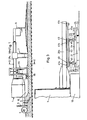
- Fig. 1 shows schematically a slipform paver 1 with a two-armed support frame 20a, 20b, the hydraulic drive units and the cabin.
- Distribution screws 4 are located at the front of the paver to distribute the fresh concrete over the pave width.
- the inner vibrators 5 are arranged behind a baffle wall 3, with which a vibration is generated in the concrete, through which the concrete is liquid and thus homogenized.
- a device 20 for introducing reinforcing bars is shown on the support frame 2 behind the pressure plate 10. This device is described in more detail below.
- transverse screed 7 is followed by the transverse screed 7 and a longitudinal screed 8 with the screed held vertically movable.
- longitudinal straightener is described in detail, for example, in DE-A-3 036 234.
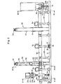
- Fig. 2 shows the device 20 for inserting the reinforcing bars viewed from the line 11-11 in Fig. 1, thus in the direction of the pavement.
- the device 20 consists of two parts arranged side by side.
- the section located symmetrically to the right of the center console has been omitted.
- this section on the right is identical to the section on the left.
- Sectional views transverse to this representation, thus in planes that run parallel to the direction of installation, are shown in FIGS. 3, 4 and 5.
- An elongated plate 21 in hollow chamber construction has a beveled underside 22, 23 in the front and rear in the direction of travel. On the rear side and above this underside 23 there is a catwalk 25 for an operator.
- Upright cross brackets 24 are provided with elongated holes 24a, 24b with vertical longitudinal expansion.
- a guide rod 30 is rigidly held by means of three equidistantly arranged T-profile pieces 31a, 31b, 31c.
- a rectangular frame 32 is provided in the two shorter side parts with slide bearings 33a, 33b which slide on the guide rod 30.
- slide bearings 33a, 33b can consist of a slidable plastic, such as NYLON.
- two height-adjustable columns 34 are rigidly attached. These columns 34 each have a U-shaped holder 35 at their lower end, which engages over the tab 24 on the plate 21 on both sides and is connected to it in height by means of bolts 36 due to the elongated holes 24a, 24b. As shown in FIG. 5, the columns 34 in turn consist of two threaded spindle stubs 34b, 34c held together by an internally threaded sleeve 34a. The length of the columns 34 can thus be adjusted in a known manner by rotating the sleeve 34a, and during operation the length of the columns 34 should be such that the plate 21 can just touch the road surface, but in no way rests on it.
- the plate 21 When the machine is moved, the plate 21 does not slide on the road surface. In the event of any unevenness in the road surface, the slab can slide over it via the slotted holes without bumping into it and thus creating a defective spot.
- the center console according to FIG. 3 is constructed in a similar manner.
- a lower center carrier 20c (not shown in FIG. 1), three T-profile pieces 41a, 41b, 41c are again rigidly and equidistantly attached, which carry two parallel central guide rods 40a, 40b.
- a rectangular frame 42 has slide bearings 43 on its shorter sides and, in the middle on these shorter sides, height-adjustable columns 44 are rigidly fastened again, the lower ends of which, with U-shaped brackets 45, overlap one of the tabs 24 mentioned and by means of bolts 46 through the elongated holes 24a these are connected in a vertically movable manner.
- these columns 44 are designed as threaded spindles and a sleeve 45 with an internal thread, which acts as a nut, is fastened to the frame 42. These columns 44 can thus also be adjusted to the correct length.
- two yoke-shaped supports 50 are rigidly attached to the plate 21 between the outer support frame 20a and the central support 20c.
- These supports 50 consist of two support columns 51, 52 which support a yoke beam 53.
- These three elements can consist of I-beams, or the two support columns 51, 52 can be designed as a hollow beam and the yoke beam 53 as two back-to-back U-beams, the latter embodiment being shown in FIG. 2.
- a vertical hydraulic cylinder 54 is articulated in the center of the yoke beam 53.
- the free end 56 of the associated piston 55 is articulated to a vibrator beam arrangement 60.
- the vibrator beam arrangement 60 is also designed as a rectangular frame made of interconnected U-beams. The longer sides are at least approximately the same length as the beam 21 and the shorter sides are shorter than the distance between the two support columns 51, 52.
- Vertical elongate plates 61 on the support columns 51, 52 form guide rails for the vibrator beam arrangement 60.
- Forks 62 arranged in pairs are attached to the vibrator beam arrangement 60 at equidistant intervals of, for example, 50 cm, and three external vibrators 64, for example, are arranged thereon. These external vibrators 64 can be used as electric motors with unbalance disks be formed on the motor shafts.
- the forks 62 are aligned precisely with slot recesses 26 in the plate 21, as FIG. 4 clearly shows.
- Holding baskets for the reinforcing bars are arranged in the slot recesses 26.
- These holding baskets consist of two spring plates 27, 28 arranged in pairs as shown in FIGS. 2 and 4.
- a horizontal hydraulic cylinder 70 can also be seen.
- a second such cylinder is present in the symmetrically arranged support of the right half of the device, not shown in FIG. 2.
- This hydraulic cylinder 70 is articulated on the slipform paver by means of a first joint 72.
- the associated piston 71 in turn is articulated with a second joint 73 in the outer support 50.
- the device 20 can slide backwards in order to remain stationary during the insertion of the reinforcing bars. After insertion, the device 20 is removed through the cylinder.
- fluid control is e.g. with a synchronized cylinder with six chambers, and in each chamber a piston with a piston rod common to all pistons, so that a displacement in all chambers causes the same displacement.
- the mode of action is as follows:
- the horizontal cylinders 70 with their pistons 71 are in the position shown in FIG. 4.
- the cylinders 54 with the pistons 55 are also in the retracted position.
- the vibration bar arrangement 60 is thus in the position designated by P1 in FIGS. 4 and 5 (this position is shown in broken lines in FIG. 4) and the forks 62 are spaced above the plate 21.
- the cylinders 54 are pressurized with fluid and the forks 63 push the reinforcing bars down out of the holding baskets.
- all six cylinders are fed with minimal pressure to overcome friction and at the same time the external vibrators 64 are activated and the forks 62 transmit vibratory vibrations to the reinforcing bars. Under this influence, the concrete liquefies at these points and the bars sink into the pavement.
- the vibrators 64 are switched off and the forks 63 with the vibrator beam arrangement 60 are pulled up by means of the cylinders 54.
- the plate 21 has not moved during this time, while the paver has continued at a constant speed, which is why the plate 21 is now at a distance from the paver.
- This position is in Fig. 4 in the position shown with dash-dotted lines.
- the reinforcement rod has thus reached the specific position and the cylinders 54 can now be supplied with pressurized fluid in order to pull the vibrating beam arrangement 60 up to the position P1 in FIG. 5.
- pressure fluid can also be supplied to the cylinders 70 in order to pull the plates 21 towards the paver.
- the paver's feed speed is around 90 - 100 m / h and thus around 2.5 cm / sec. If the cylinder 70 has a stroke length of 40 cm, only 16 seconds are available for inserting the reinforcing bars. It is therefore very important that all preparatory work has been completed so far that only the reinforcement bar has to be inserted by means of vibration during this time and then the forks are pulled out. With the proposed holding baskets 27, 28 in the plate 21, the reinforcing bars are located at the location closest to the ground. With the arrangement explained at the outset according to EP-A-51 885, however, the reinforcement bars are still held with pliers and are only released when the forks are vibrated, ie only at the point in time when the insertion point is reached.
Landscapes
- Engineering & Computer Science (AREA)
- Architecture (AREA)
- Civil Engineering (AREA)
- Structural Engineering (AREA)
- Road Paving Machines (AREA)
- Road Paving Structures (AREA)
Claims (2)
Priority Applications (1)
| Application Number | Priority Date | Filing Date | Title |
|---|---|---|---|
| AT84810221T ATE37915T1 (de) | 1984-03-14 | 1984-05-08 | Strassenbaumaschine mit einem vibrationsfertiger und mit einer vorrichtung zum einbringen von bewehrungsstaeben in eine frisch verlegte fahrbahndecke. |
Applications Claiming Priority (2)
| Application Number | Priority Date | Filing Date | Title |
|---|---|---|---|
| CH1277/84A CH679600A5 (en) | 1984-03-14 | 1984-03-14 | Road building machine with sliding shuttering vibrator |
| CH1277/84 | 1984-03-14 |
Publications (3)
| Publication Number | Publication Date |
|---|---|
| EP0154761A2 EP0154761A2 (fr) | 1985-09-18 |
| EP0154761A3 EP0154761A3 (en) | 1986-07-30 |
| EP0154761B1 true EP0154761B1 (fr) | 1988-10-12 |
Family
ID=4206654
Family Applications (1)
| Application Number | Title | Priority Date | Filing Date |
|---|---|---|---|
| EP84810221A Expired EP0154761B1 (fr) | 1984-03-14 | 1984-05-08 | Vibrofinisseuse comportant un dispositif d'insertion des barres d'armatures dans un revêtement routier fraîchement posé |
Country Status (4)
| Country | Link |
|---|---|
| EP (1) | EP0154761B1 (fr) |
| AT (1) | ATE37915T1 (fr) |
| CH (1) | CH679600A5 (fr) |
| DE (1) | DE3474574D1 (fr) |
Families Citing this family (4)
| Publication number | Priority date | Publication date | Assignee | Title |
|---|---|---|---|---|
| CH669232A5 (de) * | 1986-03-27 | 1989-02-28 | Thoma Werksvertretungen | Vorrichtung zum einbringen von bewehrungsstaeben in eine fahrbahndecke aus beton. |
| CH669233A5 (de) * | 1986-04-04 | 1989-02-28 | Thoma Werksvertretungen | Strassenbaumaschine. |
| DE3811186C2 (de) * | 1988-04-01 | 1996-10-02 | Erhard Thoma | Gleitschalungsfertiger |
| BE1011454A6 (nl) * | 1997-09-16 | 1999-09-07 | Casters Francois | Betonneermachine en deuvelapparaat hierbij aangewend. |
Citations (1)
| Publication number | Priority date | Publication date | Assignee | Title |
|---|---|---|---|---|
| DE3036234A1 (de) * | 1980-07-22 | 1982-02-11 | Walo Bertschinger AG, Zürich | Vorrichtung zur nivellierung einer betonbelagsoberflaeche und verfahren zu ihrem betrieb |
Family Cites Families (3)
| Publication number | Priority date | Publication date | Assignee | Title |
|---|---|---|---|---|
| GB1390491A (en) * | 1971-06-16 | 1975-04-16 | Rcgregor Sons Ltd Robert | Device for introducing rods dowels or the like into concrete paved carriageways |
| BE800703A (fr) * | 1973-06-08 | 1973-10-01 | Moser Hans | Dispositif pour enfoncer et positionner des goujons parallelles dans des dalles en beton |
| BE886077A (fr) * | 1980-11-07 | 1981-05-07 | Moser Andreas | Dispositif perfectionne d'enfoncement et de positionnement de goujons dans des dalles en beton |
-
1984
- 1984-03-14 CH CH1277/84A patent/CH679600A5/de not_active IP Right Cessation
- 1984-05-08 EP EP84810221A patent/EP0154761B1/fr not_active Expired
- 1984-05-08 AT AT84810221T patent/ATE37915T1/de not_active IP Right Cessation
- 1984-05-08 DE DE8484810221T patent/DE3474574D1/de not_active Expired
Patent Citations (1)
| Publication number | Priority date | Publication date | Assignee | Title |
|---|---|---|---|---|
| DE3036234A1 (de) * | 1980-07-22 | 1982-02-11 | Walo Bertschinger AG, Zürich | Vorrichtung zur nivellierung einer betonbelagsoberflaeche und verfahren zu ihrem betrieb |
Also Published As
| Publication number | Publication date |
|---|---|
| CH679600A5 (en) | 1992-03-13 |
| DE3474574D1 (en) | 1988-11-17 |
| EP0154761A3 (en) | 1986-07-30 |
| ATE37915T1 (de) | 1988-10-15 |
| EP0154761A2 (fr) | 1985-09-18 |
Similar Documents
| Publication | Publication Date | Title |
|---|---|---|
| CH669232A5 (de) | Vorrichtung zum einbringen von bewehrungsstaeben in eine fahrbahndecke aus beton. | |
| DE2159714C3 (de) | Vorrichtung zum Trennen von durch horizontale Schnitte abgegrenzten, nach dem Härten zu einem Stapel zusammenhaftenden Gasbetonelementen | |
| CH622302A5 (en) | Track-tamping machine, in particular for tamping down track points, crossings and the like | |
| CH669233A5 (de) | Strassenbaumaschine. | |
| DE1708651C3 (de) | Verfahren und Vorrichtung zum seitlichen Ausrichten von Gleisen | |
| EP0002814B1 (fr) | Coffrage pour béton formé de panneaux assemblés par clavettage | |
| CH679600A5 (en) | Road building machine with sliding shuttering vibrator | |
| DE2446768C3 (de) | Vorrichtung zum Einrütteln von Dübeln in Straßendecken aus Beton | |
| DE3811186C2 (de) | Gleitschalungsfertiger | |
| DE4014098A1 (de) | Duebelsetzer | |
| DE10337066B4 (de) | Straßenrüttelfertiger zur Ausbreitung von Konglomerat | |
| CH598429A5 (en) | Frame for applying concrete liner to excavated canal | |
| EP0460686A1 (fr) | Dispositif pour la pose d'au moins un conduit | |
| DE2524969A1 (de) | Vorrichtung zum verlegen von rohrleitungen | |
| EP0104441B1 (fr) | Dispositif pour l'insertion de goujons | |
| AT391335B (de) | Gleisstopfmaschine | |
| DE2436088A1 (de) | Verfahrbare schalungsvorrichtung | |
| DE3808754C2 (de) | Verfahren zum Einbringen von Preßpfählen und Spunddielen | |
| DE9301755U1 (de) | Spannvorrichtung zum Festhalten einer Türzarge | |
| DE1555670C2 (de) | Kraftfahrzeug zum Transport von kastenförmigen Baukörpern, insbesondere Fertiggaragen | |
| AT210812B (de) | Schalung zum Einbetonieren der unter Zugspannung stehenden Teile zweier steifer metallischer Bewehrungen | |
| DE19916884C2 (de) | Vorrichtung zur Herstellung von Spannbetonteilen | |
| DE2850939A1 (de) | Vorrichtung zur halterung von kraftgeraeten zum geraderichten einer karosserie und oder eines fahrgestelles eines fahrzeuges, beispielsweise eines kraftfahrzeuges | |
| DE4408282A1 (de) | Vorrichtung für die stufenlose Verstellung der Arbeitsbreiten eines Straßenfertigers | |
| DE19609385C2 (de) | Preßvorrichtung |
Legal Events
| Date | Code | Title | Description |
|---|---|---|---|
| PUAI | Public reference made under article 153(3) epc to a published international application that has entered the european phase |
Free format text: ORIGINAL CODE: 0009012 |
|
| AK | Designated contracting states |
Designated state(s): AT BE CH DE FR GB IT LI LU NL SE |
|
| PUAL | Search report despatched |
Free format text: ORIGINAL CODE: 0009013 |
|
| AK | Designated contracting states |
Kind code of ref document: A3 Designated state(s): AT BE CH DE FR GB IT LI LU NL SE |
|
| RAP1 | Party data changed (applicant data changed or rights of an application transferred) |
Owner name: THOMA, ERHARD L. |
|
| 17P | Request for examination filed |
Effective date: 19861119 |
|
| 17Q | First examination report despatched |
Effective date: 19871020 |
|
| GRAA | (expected) grant |
Free format text: ORIGINAL CODE: 0009210 |
|
| AK | Designated contracting states |
Kind code of ref document: B1 Designated state(s): AT BE CH DE FR GB IT LI LU NL SE |
|
| REF | Corresponds to: |
Ref document number: 37915 Country of ref document: AT Date of ref document: 19881015 Kind code of ref document: T |
|
| ITF | It: translation for a ep patent filed | ||
| GBT | Gb: translation of ep patent filed (gb section 77(6)(a)/1977) | ||
| REF | Corresponds to: |
Ref document number: 3474574 Country of ref document: DE Date of ref document: 19881117 |
|
| ET | Fr: translation filed | ||
| PLBI | Opposition filed |
Free format text: ORIGINAL CODE: 0009260 |
|
| 26 | Opposition filed |
Opponent name: ANDREAS MOSER, Effective date: 19890630 |
|
| NLR1 | Nl: opposition has been filed with the epo |
Opponent name: ANDREAS MOSER |
|
| PLBM | Termination of opposition procedure: date of legal effect published |
Free format text: ORIGINAL CODE: 0009276 |
|
| STAA | Information on the status of an ep patent application or granted ep patent |
Free format text: STATUS: OPPOSITION PROCEDURE CLOSED |
|
| 27C | Opposition proceedings terminated |
Effective date: 19891021 |
|
| PGFP | Annual fee paid to national office [announced via postgrant information from national office to epo] |
Ref country code: SE Payment date: 19910523 Year of fee payment: 8 |
|
| PGFP | Annual fee paid to national office [announced via postgrant information from national office to epo] |
Ref country code: LU Payment date: 19910529 Year of fee payment: 8 |
|
| ITTA | It: last paid annual fee | ||
| EPTA | Lu: last paid annual fee | ||
| PG25 | Lapsed in a contracting state [announced via postgrant information from national office to epo] |
Ref country code: LU Free format text: LAPSE BECAUSE OF NON-PAYMENT OF DUE FEES Effective date: 19920508 |
|
| PG25 | Lapsed in a contracting state [announced via postgrant information from national office to epo] |
Ref country code: SE Effective date: 19920509 |
|
| NLR2 | Nl: decision of opposition | ||
| EUG | Se: european patent has lapsed |
Ref document number: 84810221.6 Effective date: 19921204 |
|
| PGFP | Annual fee paid to national office [announced via postgrant information from national office to epo] |
Ref country code: GB Payment date: 19960422 Year of fee payment: 13 |
|
| PGFP | Annual fee paid to national office [announced via postgrant information from national office to epo] |
Ref country code: FR Payment date: 19960515 Year of fee payment: 13 |
|
| PGFP | Annual fee paid to national office [announced via postgrant information from national office to epo] |
Ref country code: BE Payment date: 19960521 Year of fee payment: 13 |
|
| PGFP | Annual fee paid to national office [announced via postgrant information from national office to epo] |
Ref country code: AT Payment date: 19960522 Year of fee payment: 13 |
|
| PGFP | Annual fee paid to national office [announced via postgrant information from national office to epo] |
Ref country code: CH Payment date: 19960524 Year of fee payment: 13 |
|
| PGFP | Annual fee paid to national office [announced via postgrant information from national office to epo] |
Ref country code: NL Payment date: 19960529 Year of fee payment: 13 |
|
| PG25 | Lapsed in a contracting state [announced via postgrant information from national office to epo] |
Ref country code: GB Effective date: 19970508 Ref country code: AT Effective date: 19970508 |
|
| PG25 | Lapsed in a contracting state [announced via postgrant information from national office to epo] |
Ref country code: LI Free format text: LAPSE BECAUSE OF NON-PAYMENT OF DUE FEES Effective date: 19970531 Ref country code: CH Free format text: LAPSE BECAUSE OF NON-PAYMENT OF DUE FEES Effective date: 19970531 Ref country code: BE Effective date: 19970531 |
|
| BERE | Be: lapsed |
Owner name: THOMA ERHARD L. Effective date: 19970531 |
|
| PG25 | Lapsed in a contracting state [announced via postgrant information from national office to epo] |
Ref country code: NL Effective date: 19971201 |
|
| GBPC | Gb: european patent ceased through non-payment of renewal fee |
Effective date: 19970508 |
|
| REG | Reference to a national code |
Ref country code: CH Ref legal event code: PL |
|
| PG25 | Lapsed in a contracting state [announced via postgrant information from national office to epo] |
Ref country code: FR Free format text: LAPSE BECAUSE OF NON-PAYMENT OF DUE FEES Effective date: 19980130 |
|
| NLV4 | Nl: lapsed or anulled due to non-payment of the annual fee |
Effective date: 19971201 |
|
| REG | Reference to a national code |
Ref country code: FR Ref legal event code: ST |
|
| PGFP | Annual fee paid to national office [announced via postgrant information from national office to epo] |
Ref country code: DE Payment date: 20000722 Year of fee payment: 17 |
|
| PG25 | Lapsed in a contracting state [announced via postgrant information from national office to epo] |
Ref country code: DE Free format text: LAPSE BECAUSE OF NON-PAYMENT OF DUE FEES Effective date: 20020301 |