EP0154801A2 - Coupe-circuit miniature et méthode de sa fabrication - Google Patents
Coupe-circuit miniature et méthode de sa fabrication Download PDFInfo
- Publication number
- EP0154801A2 EP0154801A2 EP85101136A EP85101136A EP0154801A2 EP 0154801 A2 EP0154801 A2 EP 0154801A2 EP 85101136 A EP85101136 A EP 85101136A EP 85101136 A EP85101136 A EP 85101136A EP 0154801 A2 EP0154801 A2 EP 0154801A2
- Authority
- EP
- European Patent Office
- Prior art keywords
- receptacle
- conductors
- conductor
- fuse
- base
- Prior art date
- Legal status (The legal status is an assumption and is not a legal conclusion. Google has not performed a legal analysis and makes no representation as to the accuracy of the status listed.)
- Granted
Links
Images
Classifications
-
- H—ELECTRICITY
- H01—ELECTRIC ELEMENTS
- H01H—ELECTRIC SWITCHES; RELAYS; SELECTORS; EMERGENCY PROTECTIVE DEVICES
- H01H85/00—Protective devices in which the current flows through a part of fusible material and this current is interrupted by displacement of the fusible material when this current becomes excessive
- H01H85/02—Details
- H01H85/04—Fuses, i.e. expendable parts of the protective device, e.g. cartridges
- H01H85/041—Fuses, i.e. expendable parts of the protective device, e.g. cartridges characterised by the type
- H01H85/0411—Miniature fuses
- H01H85/0415—Miniature fuses cartridge type
- H01H85/0417—Miniature fuses cartridge type with parallel side contacts
Definitions
- the invention relates to a miniature fuse, consisting of a plastic base, a plastic cap and two conductors passing through the base, which are bridged within the cap by a fusible conductor soldered to the conductors, and a manufacturing method for this miniature fuse.
- the invention is suitable for all fuses in which a fusible conductor is to be fastened to it in a transverse position, and for other electrical components on which another conductor is to be securely fastened to a conductor transversely to the latter. Since the invention is to be used preferably for miniature fuses of the above type, the invention is explained in the following only with reference to miniature fuses.
- the fuse element is softly soldered in the area of the ends of the pin-shaped conductors above the base. Especially when using fusible conductors made of very thin wire, soldering is carried out by hand in order to establish a reliable connection between the conductors and the fusible conductor.
- the heat transferred can influence the soldering point between the connecting pin and the fuse element in such a way that in the worst case the soldered connection opens.
- the object of the invention is therefore to create a secure attachment of the fuse element to the conductors.
- the extremely small dimensions of the fuse element and the conductor are to be taken into account as well as the fact that fuses of the type concerned here are a typical mass-produced article, with which even a small additional effort drastically increases the manufacturing costs overall can cause.
- the invention provides that a receptacle for the fusible conductor is formed on each conductor above the base and the connection between the receptacle and the fusible conductor is strengthened by melting soft solder.
- the fuse element receives an additional fastening by means of a receptacle through which the fuse element is grasped.
- a mechanical or positive connection is thus established between the fuse element and each of the two conductors of the miniature fuse before soft solder is additionally applied to the connection point. It is sufficient if the fuse element is initially only held in or on the receptacle and is finally secured by the soft soldering.
- the possibilities for training the receptacle to perform this holding function are correspondingly diverse.
- the receptacle is preferably formed by rolling or bending the upper end of the conductor.
- the fuse element can either be retracted or hooked in, depending on whether the receptacle completely or only partially encompasses the fuse element, or the fuse element is placed on the conductor before curling or bending, so that after the receptacle has been formed, the fuse element is already in it.
- the upper end of the conductor is expediently shaped flat, namely flattened, and recesses or notches are preferably provided in the region of the receptacle.
- the conductors which are usually round in cross section, are shaped flat for fastening the fuse element, so that the receptacle encloses the fuse element with a flat section.
- the notches are very important for the quality of the soldering because the solder not only adheres to the fuse element on both sides of the receptacle, but also reaches the fuse element through the notch and creates additional bridges between the fuse element and the receptacle or the conductor.
- solder adheres to the jagged surface of the receptacle much better than if the receptacle had a smooth surface.
- this form of the receptacle also has a certain capillary action when the liquid soft solder is applied, which contributes to a further improvement in the strength of the soldered connection.
- a particularly economical method for producing the miniature fuse according to the invention consists in the fact that several bases with inserted conductors, at the upper ends of which the receptacle is prepared, are arranged in a row aligned side by side, a continuous fusible conductor thread in a stretched position and a predetermined height across the upper ends of the conductors are placed against them, the receptacle is formed by rolling or bending the upper ends of the conductors to enclose and hold the fusible conductor thread, the soft solder is applied to the receptacle and the fusible conductor in this area and the connecting pieces between the fused conductors formed be separated. Then the fastening area is reground, cleaned and cleaned if necessary, whereupon the cap is placed on the base and fastened.
- the fusible conductor thread which runs simultaneously over the entire row of conductors, is embraced and held in one step in the manufacture of the receptacle by rolling or bending the upper ends of the conductor, so that the solder can be melted in the further step, after which the so-called separation formed fuse element from the common thread, whereupon the remaining work can be carried out.
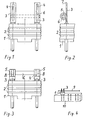
- An existing plastic, cross-sectionally circular base 1 is provided on its circumference with ribs 2 for fastening a plastic cap, not shown, and with two pin-shaped conductors 3 which pass through and are anchored in this base and whose contact pins are used, for example, to connect to printed circuit boards below the Protrude base 1.
- the conductors 3 are shaped flat and, as shown, have elongate cutouts 4. These flattened sections of the conductors 3 are rolled in, including a dash-dotted fusible conductor 6 to form a receptacle 5 comprising the fusible conductor 6, as illustrated in FIG. 2, and after prior tilting at position 7.
- the solder is then applied 8, then the separation of protruding fusible conductor parts, so that finally the final state according to FIG. 3 results.
- a device 10 which is in the form of a strip, aligned in a row next to one another. If the flattening of the conductor 6 has already taken place before the insertion of the same into the base 1, the processing in the device 10 begins with the application of a fusible conductor thread 9 in an extended position to all conductors 3. Now the conductor 3 which is attached to the Point 7 are tilted so that the fusible conductor 6 is then, as shown in Fig. 2, gripped or encompassed by the receptacle 5 formed.
- the fusible conductors 6 are separated, namely cut off from the common thread, and at the connection points may be necessary agile remaining work performed, whereupon the cap, not shown, is placed on the base 1 and firmly connected to this.
- the same size of the eyelet receptacle 5 can be used for fusible conductors of different diameters. This is because the gap between the fuse element 6 and the receptacle 5 fills the solder 8 in each case, of which as much flows into the receptacle 5 as is needed to fill the gap.
- the solder 8 is drawn into the eyelet-shaped receptacle 5.
- the receptacle 5 forms a natural protection of the soldered connection against any kind of impairment of the fastening, also against direct mechanical action, especially in the further course of production.
Landscapes
- Fuses (AREA)
- Table Devices Or Equipment (AREA)
Priority Applications (1)
| Application Number | Priority Date | Filing Date | Title |
|---|---|---|---|
| AT85101136T ATE42866T1 (de) | 1984-03-10 | 1985-02-04 | Kleinstsicherung und herstellungsverfahren hierfuer. |
Applications Claiming Priority (2)
| Application Number | Priority Date | Filing Date | Title |
|---|---|---|---|
| DE3408854 | 1984-03-10 | ||
| DE19843408854 DE3408854A1 (de) | 1984-03-10 | 1984-03-10 | Kleinstsicherung und herstellungsverfahren hierfuer |
Publications (3)
| Publication Number | Publication Date |
|---|---|
| EP0154801A2 true EP0154801A2 (fr) | 1985-09-18 |
| EP0154801A3 EP0154801A3 (en) | 1986-04-02 |
| EP0154801B1 EP0154801B1 (fr) | 1989-05-03 |
Family
ID=6230133
Family Applications (1)
| Application Number | Title | Priority Date | Filing Date |
|---|---|---|---|
| EP85101136A Expired EP0154801B1 (fr) | 1984-03-10 | 1985-02-04 | Coupe-circuit miniature et méthode de sa fabrication |
Country Status (5)
| Country | Link |
|---|---|
| US (1) | US4628293A (fr) |
| EP (1) | EP0154801B1 (fr) |
| JP (1) | JPS60258824A (fr) |
| AT (1) | ATE42866T1 (fr) |
| DE (2) | DE3408854A1 (fr) |
Cited By (2)
| Publication number | Priority date | Publication date | Assignee | Title |
|---|---|---|---|---|
| GB2204457A (en) * | 1987-05-05 | 1988-11-09 | Dubilier Plc | Sub-miniature fuse |
| EP0484703A3 (en) * | 1990-11-05 | 1993-03-24 | Wickmann-Werke Gmbh | Electrical fuse |
Families Citing this family (10)
| Publication number | Priority date | Publication date | Assignee | Title |
|---|---|---|---|---|
| JPH0720828Y2 (ja) * | 1989-06-14 | 1995-05-15 | エス・オー・シー株式会社 | 超小型電流ヒューズ |
| US5287079A (en) * | 1992-11-09 | 1994-02-15 | Cooper Industries, Inc. | Sub-miniature plastic fuse |
| DE19803605B4 (de) * | 1998-01-30 | 2004-08-26 | Wickmann-Werke Gmbh | Verfahren zur Herstellung elektrischer Sicherungen |
| US6462472B1 (en) * | 2000-04-12 | 2002-10-08 | Chen Hsien Huang | Fixing structure for safety fuse of Christmas lamp |
| JP2009540522A (ja) * | 2006-06-16 | 2009-11-19 | スマート エレクトロニクス インク | 表面実装型の小型ヒューズ及びその製造方法 |
| US20080143471A1 (en) * | 2006-12-15 | 2008-06-19 | Chun-Chang Yen | Fuse assembly |
| US20090108980A1 (en) * | 2007-10-09 | 2009-04-30 | Littelfuse, Inc. | Fuse providing overcurrent and thermal protection |
| US8576041B2 (en) * | 2008-12-17 | 2013-11-05 | Cooper Technologies Company | Radial fuse base and assembly |
| KR101038401B1 (ko) | 2009-04-21 | 2011-06-03 | 스마트전자 주식회사 | 소형퓨즈 및 그 제조방법 |
| DE102009019059A1 (de) * | 2009-04-27 | 2010-11-04 | Chun-Chang Yen | Automatischer Fertigungsprozeß für die Basis einer Sicherung sowie eine geeignete Konstruktion für die Basis |
Family Cites Families (11)
| Publication number | Priority date | Publication date | Assignee | Title |
|---|---|---|---|---|
| US3123696A (en) * | 1964-03-03 | Cffalq l | ||
| US1008411A (en) * | 1908-11-09 | 1911-11-14 | Henry A Hills | Safety device for electrically-heated implements. |
| FR762124A (fr) * | 1932-11-15 | 1934-04-04 | Barette de coupe-circuit en matière isolante moulée avec cloisonnement évitant la propagation de l'arc électrique | |
| FR948836A (fr) * | 1947-06-19 | 1949-08-11 | Procédé de fabrication de porte-fusibles | |
| US3253244A (en) * | 1963-11-06 | 1966-05-24 | Indak Mfg Corp | Electrical resistors |
| JPS5852289B2 (ja) * | 1979-09-08 | 1983-11-21 | エス・オ−・シ−株式会社 | 超速断型小型ヒユ−ズ |
| EP0041966A1 (fr) * | 1979-12-03 | 1981-12-23 | Kenneth E Beswick Limited | Procede de fabrication de fusibles electriques enfichables et fusibles produits par ce procede |
| JPS56112856U (fr) * | 1980-01-31 | 1981-08-31 | ||
| JPS58184219A (ja) * | 1982-04-21 | 1983-10-27 | 日本電気ホームエレクトロニクス株式会社 | 温度ヒユ−ズの製造方法 |
| US4483064A (en) * | 1982-07-22 | 1984-11-20 | Bel Fuse, Inc. | Process of multiple fuse construction |
| DE8411568U1 (de) * | 1984-04-13 | 1984-08-23 | Wickmann-Werke GmbH, 5810 Witten | Miniatursicherung |
-
1984
- 1984-03-10 DE DE19843408854 patent/DE3408854A1/de not_active Withdrawn
-
1985
- 1985-02-04 DE DE8585101136T patent/DE3570011D1/de not_active Expired
- 1985-02-04 AT AT85101136T patent/ATE42866T1/de not_active IP Right Cessation
- 1985-02-04 EP EP85101136A patent/EP0154801B1/fr not_active Expired
- 1985-03-05 US US06/708,532 patent/US4628293A/en not_active Expired - Lifetime
- 1985-03-11 JP JP60048091A patent/JPS60258824A/ja active Granted
Cited By (2)
| Publication number | Priority date | Publication date | Assignee | Title |
|---|---|---|---|---|
| GB2204457A (en) * | 1987-05-05 | 1988-11-09 | Dubilier Plc | Sub-miniature fuse |
| EP0484703A3 (en) * | 1990-11-05 | 1993-03-24 | Wickmann-Werke Gmbh | Electrical fuse |
Also Published As
| Publication number | Publication date |
|---|---|
| US4628293A (en) | 1986-12-09 |
| JPH0542767B2 (fr) | 1993-06-29 |
| DE3570011D1 (en) | 1989-06-08 |
| JPS60258824A (ja) | 1985-12-20 |
| DE3408854A1 (de) | 1985-09-12 |
| ATE42866T1 (de) | 1989-05-15 |
| EP0154801A3 (en) | 1986-04-02 |
| EP0154801B1 (fr) | 1989-05-03 |
Similar Documents
| Publication | Publication Date | Title |
|---|---|---|
| DE3808971A1 (de) | Zusammengesetztes bauelement | |
| DE69109368T2 (de) | Sicherungseinheit, insbesondere für gedruckte Schaltung. | |
| EP0154801B1 (fr) | Coupe-circuit miniature et méthode de sa fabrication | |
| DE2444892C3 (de) | Verfahren zur Herstellung von streifenförmigen Anschlußelementen | |
| DE2234961B2 (de) | Verfahren zur Herstellung von Steckern für Schaltplatten | |
| DE68913843T2 (de) | Elektrischer Steckverbinder mit einem Lötmittel. | |
| DE1293268B (de) | Schaltungsmodul | |
| DE3010876A1 (de) | Verfahren zur herstellung einer leiterplatte | |
| DE3134381A1 (de) | Verfahren zur herstellung von stecksockeln fuer leuchtdioden-anzeigeelemente | |
| DE3304263A1 (de) | Glasschmelzsicherungen sowie verfahren zu ihrer herstellung | |
| DE2603151C3 (de) | Bauelement für Schalt- und/oder Trennleisten in Verteilern für Fernmeldeanlagen | |
| DE19636237A1 (de) | Schaltkontaktsystem eines Niederspannungs-Leistungsschalters mit biegsamen Leitern | |
| EP0471922A2 (fr) | Elément fusible | |
| DE1916554B2 (de) | Verfahren zum Herstellen von Halbleitergleichrichteranordnungen | |
| DE1962175A1 (de) | Elektrisches Geraet,insbesondere Zungenschalter | |
| DE3724033C2 (fr) | ||
| DE2509763C3 (de) | Mehrdraht-Sauerstoffelektrode und Verfahren zur Herstellung derselben | |
| DE3150125A1 (de) | Verfahren zur herstellung eines relais und danach hergestelltes relais | |
| DE1963313B2 (de) | Klemmelement zum loetfreien anschluss isolierter elektrischer leiter | |
| DE3715093A1 (de) | Verfahren zum anschliessen einer spule | |
| DE2820002A1 (de) | Elektrisches anschlussbauteil fuer die bestueckung einer elektrischen leiterplatte | |
| DE602004001871T2 (de) | Kontaktbuchse mit Lötmasse und Herstellungsverfahren | |
| DE19803605B4 (de) | Verfahren zur Herstellung elektrischer Sicherungen | |
| DE19851532A1 (de) | Sicherungshalter | |
| AT401125B (de) | Verfahren zur herstellung einer thermosicherung |
Legal Events
| Date | Code | Title | Description |
|---|---|---|---|
| PUAI | Public reference made under article 153(3) epc to a published international application that has entered the european phase |
Free format text: ORIGINAL CODE: 0009012 |
|
| AK | Designated contracting states |
Designated state(s): AT BE CH DE FR GB IT LI LU NL SE |
|
| PUAL | Search report despatched |
Free format text: ORIGINAL CODE: 0009013 |
|
| AK | Designated contracting states |
Kind code of ref document: A3 Designated state(s): AT BE CH DE FR GB IT LI LU NL SE |
|
| 17P | Request for examination filed |
Effective date: 19860515 |
|
| 17Q | First examination report despatched |
Effective date: 19871027 |
|
| ITF | It: translation for a ep patent filed | ||
| GRAA | (expected) grant |
Free format text: ORIGINAL CODE: 0009210 |
|
| AK | Designated contracting states |
Kind code of ref document: B1 Designated state(s): AT BE CH DE FR GB IT LI LU NL SE |
|
| PG25 | Lapsed in a contracting state [announced via postgrant information from national office to epo] |
Ref country code: SE Effective date: 19890503 Ref country code: BE Effective date: 19890503 |
|
| REF | Corresponds to: |
Ref document number: 42866 Country of ref document: AT Date of ref document: 19890515 Kind code of ref document: T |
|
| REF | Corresponds to: |
Ref document number: 3570011 Country of ref document: DE Date of ref document: 19890608 |
|
| ET | Fr: translation filed | ||
| GBT | Gb: translation of ep patent filed (gb section 77(6)(a)/1977) | ||
| PG25 | Lapsed in a contracting state [announced via postgrant information from national office to epo] |
Ref country code: AT Effective date: 19900204 |
|
| PG25 | Lapsed in a contracting state [announced via postgrant information from national office to epo] |
Ref country code: LU Free format text: LAPSE BECAUSE OF NON-PAYMENT OF DUE FEES Effective date: 19900228 Ref country code: LI Effective date: 19900228 Ref country code: CH Effective date: 19900228 |
|
| PLBE | No opposition filed within time limit |
Free format text: ORIGINAL CODE: 0009261 |
|
| STAA | Information on the status of an ep patent application or granted ep patent |
Free format text: STATUS: NO OPPOSITION FILED WITHIN TIME LIMIT |
|
| 26N | No opposition filed | ||
| REG | Reference to a national code |
Ref country code: CH Ref legal event code: PL |
|
| ITTA | It: last paid annual fee | ||
| REG | Reference to a national code |
Ref country code: GB Ref legal event code: IF02 |
|
| PGFP | Annual fee paid to national office [announced via postgrant information from national office to epo] |
Ref country code: DE Payment date: 20030129 Year of fee payment: 19 |
|
| PGFP | Annual fee paid to national office [announced via postgrant information from national office to epo] |
Ref country code: GB Payment date: 20030130 Year of fee payment: 19 |
|
| PGFP | Annual fee paid to national office [announced via postgrant information from national office to epo] |
Ref country code: NL Payment date: 20030204 Year of fee payment: 19 |
|
| PGFP | Annual fee paid to national office [announced via postgrant information from national office to epo] |
Ref country code: FR Payment date: 20030206 Year of fee payment: 19 |
|
| PG25 | Lapsed in a contracting state [announced via postgrant information from national office to epo] |
Ref country code: GB Free format text: LAPSE BECAUSE OF NON-PAYMENT OF DUE FEES Effective date: 20040204 |
|
| PG25 | Lapsed in a contracting state [announced via postgrant information from national office to epo] |
Ref country code: NL Free format text: LAPSE BECAUSE OF NON-PAYMENT OF DUE FEES Effective date: 20040901 Ref country code: DE Free format text: LAPSE BECAUSE OF NON-PAYMENT OF DUE FEES Effective date: 20040901 |
|
| GBPC | Gb: european patent ceased through non-payment of renewal fee |
Effective date: 20040204 |
|
| PG25 | Lapsed in a contracting state [announced via postgrant information from national office to epo] |
Ref country code: FR Free format text: LAPSE BECAUSE OF NON-PAYMENT OF DUE FEES Effective date: 20041029 |
|
| NLV4 | Nl: lapsed or anulled due to non-payment of the annual fee |
Effective date: 20040901 |
|
| REG | Reference to a national code |
Ref country code: FR Ref legal event code: ST |