EP0154957A2 - Machine de coupe avec disque rotatif pour revêtements routiers - Google Patents
Machine de coupe avec disque rotatif pour revêtements routiers Download PDFInfo
- Publication number
- EP0154957A2 EP0154957A2 EP85102716A EP85102716A EP0154957A2 EP 0154957 A2 EP0154957 A2 EP 0154957A2 EP 85102716 A EP85102716 A EP 85102716A EP 85102716 A EP85102716 A EP 85102716A EP 0154957 A2 EP0154957 A2 EP 0154957A2
- Authority
- EP
- European Patent Office
- Prior art keywords
- cylinder
- slide
- hammer
- rotary disk
- guide cylinder
- Prior art date
- Legal status (The legal status is an assumption and is not a legal conclusion. Google has not performed a legal analysis and makes no representation as to the accuracy of the status listed.)
- Withdrawn
Links
Images
Classifications
-
- E—FIXED CONSTRUCTIONS
- E01—CONSTRUCTION OF ROADS, RAILWAYS, OR BRIDGES
- E01C—CONSTRUCTION OF, OR SURFACES FOR, ROADS, SPORTS GROUNDS, OR THE LIKE; MACHINES OR AUXILIARY TOOLS FOR CONSTRUCTION OR REPAIR
- E01C23/00—Auxiliary devices or arrangements for constructing, repairing, reconditioning, or taking-up road or like surfaces
- E01C23/06—Devices or arrangements for working the finished surface; Devices for repairing or reconditioning the surface of damaged paving; Recycling in place or on the road
- E01C23/09—Devices or arrangements for working the finished surface; Devices for repairing or reconditioning the surface of damaged paving; Recycling in place or on the road for forming cuts, grooves, or recesses, e.g. for making joints or channels for markings, for cutting-out sections to be removed; for cleaning, treating, or filling cuts, grooves, recesses, or fissures; for trimming paving edges
- E01C23/0906—Devices or arrangements for working the finished surface; Devices for repairing or reconditioning the surface of damaged paving; Recycling in place or on the road for forming cuts, grooves, or recesses, e.g. for making joints or channels for markings, for cutting-out sections to be removed; for cleaning, treating, or filling cuts, grooves, recesses, or fissures; for trimming paving edges for forming, opening-out, cleaning, drying or heating cuts, grooves, recesses or, excluding forming, cracks, e.g. cleaning by sand-blasting or air-jet ; for trimming paving edges
- E01C23/0926—Devices or arrangements for working the finished surface; Devices for repairing or reconditioning the surface of damaged paving; Recycling in place or on the road for forming cuts, grooves, or recesses, e.g. for making joints or channels for markings, for cutting-out sections to be removed; for cleaning, treating, or filling cuts, grooves, recesses, or fissures; for trimming paving edges for forming, opening-out, cleaning, drying or heating cuts, grooves, recesses or, excluding forming, cracks, e.g. cleaning by sand-blasting or air-jet ; for trimming paving edges with power-driven tools, e.g. vibrated, percussive cutters
- E01C23/0933—Devices or arrangements for working the finished surface; Devices for repairing or reconditioning the surface of damaged paving; Recycling in place or on the road for forming cuts, grooves, or recesses, e.g. for making joints or channels for markings, for cutting-out sections to be removed; for cleaning, treating, or filling cuts, grooves, recesses, or fissures; for trimming paving edges for forming, opening-out, cleaning, drying or heating cuts, grooves, recesses or, excluding forming, cracks, e.g. cleaning by sand-blasting or air-jet ; for trimming paving edges with power-driven tools, e.g. vibrated, percussive cutters rotary, e.g. circular-saw joint cutters
Definitions
- This invention relates to a device for cutting through pavement courses with a rotary disk tool.
- a device for cutting through pavement courses with rotary disk tools comprises a pneumatic or hydraulic hammer having a shank whereto a bracket is secured which carries a rotary disk tool bit set for rotation in a plane transverse to the road course, said bracket having a ground-contacting shoe articulated laterally thereto.
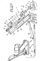
- the device for cutting through road courses which comprises a pneumatic of hydraulic hammer 2 of a conventional type.
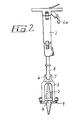
- the device 1 is provided with a cutter bit including a rotatable disk 3 mounted for free rotary movement on an axial pin 4 which is carried at the ends of a bracket 5.
- the bracket 5 defines at the top an attachment seat 6 for a conical coupling 7 formed by the enlarged tip of the shank 8 of the hammer 2.
- the centre of the rotatable disk 3 is laid on the plane containing the axis of the hammer 2.
- the rotatable disk 3 has two faces converging toward its edge as shown in Figure 2.
- a ground-engaging shoe 9 is articulated to the pin 4 externally to the bracket 5 and raised at the leading end in the forward direction of the device and enclosing the disk 3.
- the hammer 2 is carried on a slide 10 equipped with suitable forward movement means and communicates through a pipe 2a with a source of pressurized fluid, for example a compressor, in a manner known per se, and no further described or illustrated herein.
- the slide 10 has, articulated frontally thereto on a cross- pin 11, a guide cylinder 12 having a square inside cross-section, wherein a complementary cross-section rod 13 is slidable which extends out of the cylinder.
- the rod 13 carries at its free end a bracket 14 whereto there is fastened, as by screw means 15 and with the interposition of a set of adjustment spacers 16, a plate 17 which bears onto a pair of external protuberances 18 on the cylinder 12.
- the plate 17 is formed with a pair of supports 19 in the proximity of the area of attachment of the rod 13 to the bracket 14, said supports 19 being adapted for cooperation with respective brackets 20 in clamping the transverse handles 21 of the hammer 2 to the plate 17.
- the hammer 2 itself also bears onto the plate 17, through an elastic packing 22 and,accordingly, lies parallel to the guide cylinder 12.
- the inclination of the guide cylinder 12 is adjustable in the vertical plane through inclination control means which, in the illustrated embodiment comprises a pneumatic cylinder 23 communicating with a source of pressurized fluid in a known manner (not illustrated) which is articulated at its ends, 24 and 25 respectively, to the slide 10 and a flange 26 rigid with the guide cylinder 12.
- inclination control means which, in the illustrated embodiment comprises a pneumatic cylinder 23 communicating with a source of pressurized fluid in a known manner (not illustrated) which is articulated at its ends, 24 and 25 respectively, to the slide 10 and a flange 26 rigid with the guide cylinder 12.
- the pneumatic cylinder 23, may be replaced by any suitable means for controlling the inclination of the guide cylinder 12, such as power assisted means or even a mechanical jack arrangement.
- the flange 26 is provided with a pair of holes 27 whose centres are arranged to lie on an arc radius of the cross pin 11 corresponding with the centres of a plurality of holes 28 formed in a further flange 29 which projects from the slide 10. Said pair of holes 27 being axially alignable with any equally spaced pair of said plurality of holes 28, thereafter locking means such as screw means can be inserted through the axially aligned holes 27, 28 to "lock" the guide cylinder 12 at a desired inclination.
- the flanges 26 and 29 are arranged to face each other and the articulation pin 11 is passed therethrough. Also adjustable is the position of the rod 13 along the guide cylinder 12, which may also be locked through the insertion of screw means engaging respective holes 30.
- a vibrating plate indicated generally at 31 in the drawing and not described in detail because known per se is preferably mounted on the slide 10.
- Appropriate holes 32 are provided in the slide 10 for mounting the vibrating plate 31.
- the cylinder 12 may be mounted on a carriage which is moved forward by a pneumatic drive.
- the hammer 2 In the working position, the hammer 2 has an axis which leans backwards with respect to the direction of forward movement A of the device 1, this inclination being determined by the position of the guide cylinder 12 whereto said hammer is parallely secured.
- the inclination is adjustable, through the pneumatic cylinder 23, according to the characteristics of the pavement course to be cut.
Landscapes
- Engineering & Computer Science (AREA)
- Mining & Mineral Resources (AREA)
- Architecture (AREA)
- Civil Engineering (AREA)
- Structural Engineering (AREA)
- Road Repair (AREA)
Applications Claiming Priority (2)
| Application Number | Priority Date | Filing Date | Title |
|---|---|---|---|
| ITBO1984U4817U IT8404817U1 (it) | 1984-03-16 | 1984-03-16 | Dispositivo per il taglio di manti stradali con utensile a disco rotante. |
| IT481784U | 1984-03-16 |
Publications (2)
| Publication Number | Publication Date |
|---|---|
| EP0154957A2 true EP0154957A2 (fr) | 1985-09-18 |
| EP0154957A3 EP0154957A3 (fr) | 1987-01-28 |
Family
ID=11114256
Family Applications (1)
| Application Number | Title | Priority Date | Filing Date |
|---|---|---|---|
| EP85102716A Withdrawn EP0154957A3 (fr) | 1984-03-16 | 1985-03-09 | Machine de coupe avec disque rotatif pour revêtements routiers |
Country Status (2)
| Country | Link |
|---|---|
| EP (1) | EP0154957A3 (fr) |
| IT (1) | IT8404817U1 (fr) |
Cited By (2)
| Publication number | Priority date | Publication date | Assignee | Title |
|---|---|---|---|---|
| GB2230997A (en) * | 1989-03-29 | 1990-11-07 | Matt Norbert Senger | Compacting machine including a wheel |
| US5934834A (en) * | 1996-09-16 | 1999-08-10 | S.D.T.O. | Machine for making grooves in the ground |
Family Cites Families (7)
| Publication number | Priority date | Publication date | Assignee | Title |
|---|---|---|---|---|
| DE890659C (de) * | 1953-08-13 | Frankfurter Maschinenbau-Aktiengesellschaft voTm. Pokorny 6- Wittekind, Frankfurt/M | Verfahren und Vorrichtung zur Erzeugung von Nuten oder Rillen in Betonflächen, insbesondere Straßendecken | |
| FR1103648A (fr) * | 1953-07-04 | 1955-11-04 | Allg Baumaschinen Ges M B H | Compresseur vibrateur à plaque, à conduite manuelle, actionné par un moteur à combustion |
| DE1175261B (de) * | 1962-03-16 | 1964-08-06 | Berthold Wurmbach | Randabschneidemaschine fuer bituminoese Fahrbahnbelaege |
| DE2356527A1 (de) * | 1973-11-13 | 1975-05-22 | Voegele Ag J | Vorrichtung zur herstellung von nuten, insbesondere zur aufnahme von dauermarkierungen, in strassendecken |
| DE2506617A1 (de) * | 1975-02-17 | 1976-08-26 | Possehl Gmbh | Fugenschneidmaschine |
| SE416322B (sv) * | 1978-05-08 | 1980-12-15 | Tord Erik Birger Eriksson | Asfaltskerare |
| US4331362A (en) * | 1980-08-15 | 1982-05-25 | Talbert Carroll G | Portable cutting device for attachment to blades of earth moving machines |
-
1984
- 1984-03-16 IT ITBO1984U4817U patent/IT8404817U1/it unknown
-
1985
- 1985-03-09 EP EP85102716A patent/EP0154957A3/fr not_active Withdrawn
Cited By (2)
| Publication number | Priority date | Publication date | Assignee | Title |
|---|---|---|---|---|
| GB2230997A (en) * | 1989-03-29 | 1990-11-07 | Matt Norbert Senger | Compacting machine including a wheel |
| US5934834A (en) * | 1996-09-16 | 1999-08-10 | S.D.T.O. | Machine for making grooves in the ground |
Also Published As
| Publication number | Publication date |
|---|---|
| EP0154957A3 (fr) | 1987-01-28 |
| IT8404817V0 (it) | 1984-03-16 |
| IT8404817U1 (it) | 1985-09-16 |
Similar Documents
| Publication | Publication Date | Title |
|---|---|---|
| US2332561A (en) | Material handling apparatus | |
| US4924945A (en) | Soil leveling apparatus with improved scraper member | |
| DE2550735C2 (de) | Gerät zum Ausheben von Gräben und zum Verlegen von Be- oder Entwässerungsrohren | |
| US2882977A (en) | Gardening machine | |
| US4852946A (en) | Surface working accessory and method | |
| CN106489366B (zh) | 开沟机 | |
| EP0142277A1 (fr) | Equipement pour le fraisage des chaussées | |
| DE202022001468U1 (de) | Offene Schutzhaube mit integrierter Absaugung für ein fahrbares Gerät zum Trockenschnitt in Oberflächen | |
| US20080205983A1 (en) | Slot cutting apparatus | |
| EP0310074B1 (fr) | Dispositif de fraisage destiné à être monté à un appareil mobile | |
| DE102004050183B3 (de) | Kombiniertes Fugenfräs- und Schleifgerät auf Tretrollerbasis | |
| DE2701473A1 (de) | Mit einer vibrationsvorrichtung versehener pflug, insbesondere zum verlegen von kabeln | |
| EP0154957A2 (fr) | Machine de coupe avec disque rotatif pour revêtements routiers | |
| DE2701474A1 (de) | Pflug, insbesondere zum verlegen von kabeln | |
| US4553608A (en) | Scraper with ripper assembly | |
| EP0127587B1 (fr) | Unité de désagrégation mobile pour défricher et déblayer des terrains inégaux, pour préparer des assiettes de routes et des coffrages routiers, pour travaux de mines à ciel ouvert et cetera | |
| US4466491A (en) | Apparatus for removing rocks and objects | |
| US5755048A (en) | Pavement cutter | |
| JP6137871B2 (ja) | 中央制御で調節されるレベリング・ボードを備えた作業機械 | |
| CN210868638U (zh) | 一种旋耕机 | |
| DE4016759C2 (de) | Hydraulikhammer-Löffel-Kombination | |
| KR102117289B1 (ko) | 탑승형 도로 절단장치 | |
| DE102008054620A1 (de) | Handgeführtes Bodenbearbeitungsgerät | |
| CN223182618U (zh) | 一种农业种植土壤用的松土装置 | |
| CN218019404U (zh) | 一种用于竖向混凝土结构单侧快速切割的装置 |
Legal Events
| Date | Code | Title | Description |
|---|---|---|---|
| PUAI | Public reference made under article 153(3) epc to a published international application that has entered the european phase |
Free format text: ORIGINAL CODE: 0009012 |
|
| AK | Designated contracting states |
Designated state(s): DE FR GB |
|
| PUAL | Search report despatched |
Free format text: ORIGINAL CODE: 0009013 |
|
| AK | Designated contracting states |
Kind code of ref document: A3 Designated state(s): DE FR GB |
|
| STAA | Information on the status of an ep patent application or granted ep patent |
Free format text: STATUS: THE APPLICATION HAS BEEN WITHDRAWN |
|
| 18D | Application deemed to be withdrawn |
Effective date: 19870729 |
|
| 18W | Application withdrawn |
Withdrawal date: 19871027 |
|
| RIN1 | Information on inventor provided before grant (corrected) |
Inventor name: PELLICIARI, FULVIO |