EP0154971A2 - Süsswassergewinnungsvorrichtung und/oder Bewässerungsvorrichtung - Google Patents
Süsswassergewinnungsvorrichtung und/oder Bewässerungsvorrichtung Download PDFInfo
- Publication number
- EP0154971A2 EP0154971A2 EP85102767A EP85102767A EP0154971A2 EP 0154971 A2 EP0154971 A2 EP 0154971A2 EP 85102767 A EP85102767 A EP 85102767A EP 85102767 A EP85102767 A EP 85102767A EP 0154971 A2 EP0154971 A2 EP 0154971A2
- Authority
- EP
- European Patent Office
- Prior art keywords
- water
- fresh water
- water production
- vessels
- lid
- Prior art date
- Legal status (The legal status is an assumption and is not a legal conclusion. Google has not performed a legal analysis and makes no representation as to the accuracy of the status listed.)
- Granted
Links
Images
Classifications
-
- E—FIXED CONSTRUCTIONS
- E03—WATER SUPPLY; SEWERAGE
- E03B—INSTALLATIONS OR METHODS FOR OBTAINING, COLLECTING, OR DISTRIBUTING WATER
- E03B3/00—Methods or installations for obtaining or collecting drinking water or tap water
- E03B3/40—Other devices for confining, e.g. trenches, drainage
-
- B—PERFORMING OPERATIONS; TRANSPORTING
- B01—PHYSICAL OR CHEMICAL PROCESSES OR APPARATUS IN GENERAL
- B01D—SEPARATION
- B01D5/00—Condensation of vapours; Recovering volatile solvents by condensation
- B01D5/0057—Condensation of vapours; Recovering volatile solvents by condensation in combination with other processes
- B01D5/006—Condensation of vapours; Recovering volatile solvents by condensation in combination with other processes with evaporation or distillation
- B01D5/0066—Dome shaped condensation
-
- C—CHEMISTRY; METALLURGY
- C02—TREATMENT OF WATER, WASTE WATER, SEWAGE, OR SLUDGE
- C02F—TREATMENT OF WATER, WASTE WATER, SEWAGE, OR SLUDGE
- C02F1/00—Treatment of water, waste water, or sewage
- C02F1/02—Treatment of water, waste water, or sewage by heating
- C02F1/04—Treatment of water, waste water, or sewage by heating by distillation or evaporation
- C02F1/14—Treatment of water, waste water, or sewage by heating by distillation or evaporation using solar energy
-
- Y—GENERAL TAGGING OF NEW TECHNOLOGICAL DEVELOPMENTS; GENERAL TAGGING OF CROSS-SECTIONAL TECHNOLOGIES SPANNING OVER SEVERAL SECTIONS OF THE IPC; TECHNICAL SUBJECTS COVERED BY FORMER USPC CROSS-REFERENCE ART COLLECTIONS [XRACs] AND DIGESTS
- Y02—TECHNOLOGIES OR APPLICATIONS FOR MITIGATION OR ADAPTATION AGAINST CLIMATE CHANGE
- Y02A—TECHNOLOGIES FOR ADAPTATION TO CLIMATE CHANGE
- Y02A20/00—Water conservation; Efficient water supply; Efficient water use
- Y02A20/20—Controlling water pollution; Waste water treatment
- Y02A20/208—Off-grid powered water treatment
- Y02A20/212—Solar-powered wastewater sewage treatment, e.g. spray evaporation
Definitions
- the invention relates to a fresh water extraction device and / or irrigation device, consisting of tubular interconnected vessels which are connected to water supply lines and overflow lines.
- the invention addresses the problem of a fresh water extraction device and / or irrigation device create that works without complicated facilities, especially without mechanically moving parts.
- the use of salt water should also be included here.
- the invention is essentially based on the idea of bringing saline water, which is relatively warmed to the environment, into a closed space, from which water vapor can escape through a water vapor permeable cover. Since the area of the lid is at a low temperature due to the soil above it, the water vapor liquefies and the soil above tries to absorb this water so that it can be supplied to the roots of plants. However, the containers do not have to be in the ground and in this case the lid according to the invention can be made of waterproof material. Fresh water condenses on it and is collected via the gutters.
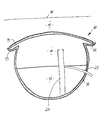
- the figure shows a cross-sectional view of a device according to the invention located in the ground.
- FIG. 10 shows an elongated container which has been laid with a suitable slope in the soil 15 below the surface 16 of the earth.
- This container consists of a lower part 11, which consists of a waterproof material.
- the container 11 is open at the top and has grooves 12 and 13 on both sides.
- the water inlets and a water level control device are not shown in the figure.
- the heater and the area from which the water is taken are also not shown.
- the container 10 can be connected to a body of water, for example the sea, via a solar collector.
- salt water enters the vessel 10, which has an increased temperature in comparison to that of the vessel 10.
- the water therefore only partially collects in area 17, it rises in part as water vapor 18 and penetrates the lid 14, which of course depends on the porosity.
- the water condenses on the cover and reaches the soil 15, so that plant roots located there are supplied with water.
- the water also collects on the lid 10 and runs into the channels 12 and 13, from where it can be removed via suitable devices, e.g. for fresh water reservoirs.
- a riser pipe is shown in the figure, which has a ventilation opening in the upper region above the water level.
- This riser pipe leads into the lower part of the container 11.
- the riser pipe itself is connected to a drain pipe 21, so that the water level in the interior of the container 10 is approximately at the junction between the drain pipe 21 and the riser pipe 20.
- the draining water can be returned to the salt water reservoir, but it can also be returned to the circuit after heating.
- the purpose of the arrangement of the riser pipe is that the saline water located in the lower part of the container, which is also lower Temperature, is derived and not about the water on the surface of the water level, which has a higher temperature. In this way, the efficiency of the plant can be increased.
Landscapes
- Engineering & Computer Science (AREA)
- Life Sciences & Earth Sciences (AREA)
- Hydrology & Water Resources (AREA)
- Chemical & Material Sciences (AREA)
- Environmental & Geological Engineering (AREA)
- Water Supply & Treatment (AREA)
- Chemical Kinetics & Catalysis (AREA)
- Sustainable Development (AREA)
- Sustainable Energy (AREA)
- Organic Chemistry (AREA)
- Health & Medical Sciences (AREA)
- Public Health (AREA)
- Heat Treatment Of Water, Waste Water Or Sewage (AREA)
- Seasonings (AREA)
Abstract
Description
- Die Erfindung bezieht sich auf eine Süßwassergewinnungsvorrichtung und/oder Bewässerungsvorrichtung, bestehend aus rohrförmigen miteinander verbundenen Gefäßen, die an Wasserzufuhrleitungen und Überlaufleitungen angeschlossen sind.
- Wasser ist bei jeder Temperatur bestrebt, vom flüssigen in den dampfförmigen Zustand überzugehen.Bei höheren Temperaturen wird jedoch die Wassermenge größer, die den flüssigen Zustand verläßt. Der Wasserdampf ist weiterhin bestrebt, möglichst nach oben zu entweichen, dabei übt aber der Feuchtigkeitsgehalt der Umgebung einen Einfluß aus, da ein trockenes Medium Wasser stärker anzieht als ein feuchtes.
- Die Erfindung befaßt sich mit dem Problem, eine Süßwassergewinnungsvorrichtung und/oder Bewässerungsvorrichtung zu schaffen, die ohne komplizierte Einrichtungen, insbesondere ohne mechanisch bewegte Teile, arbeitet. Hierbei soll vorwiegend auch der Einsatz von Salzwasser mit eingeschlossen sein.
- Erreicht wird dies durch eine Vorrichtung gemäß den Ansprüchen.
- Im wesentlichen beruht die Erfindung auf der Idee, salzhaltiges Wasser, welches zur Umgebung relativ erwärmt ist, in einen geschlossenen Raum zu bringen, aus welchem Wasserdampf durch einen wasserdampfdurchlässigen Deckel entweichen kann. Da sich der Bereich des Deckels durch das darüber befindliche Erdreich auf einer niedrigen Temperatur befindet, verflüssigt sich der Wasserdampf, und das darüber befindliche Erdreich ist bestrebt, dieses Wasser aufzunehmen, so daß es den Wurzeln von Pflanzen zugeführt werden kann. Jedoch müssen sich die Behälter nicht im Erdreich befinden und in diesem Fall kann der Deckel gemäß der Erfindung aus wasserundurchlässigem Material bestehen. An ihm schlägt sich Süßwasser nieder und wird über die Sammlerrinnen gesammelt.
- Mit Hilfe der Vorrichtung gemäß der Erfindung ist es lediglich notwendig, Salzwasser aus einem Salzwasserreservoir in den Behälter zu pumpen, der Wirkungsgrad der Süßwassergewinnung kann jedoch durch Erwärmung dieses Wassers erhöht werden.
- Die Erfindung wird nachstehend an Hand der Zeichnung beispielsweise erläutert.
- Die Figur zeigt eine Querschnittsansicht einer im Erdreich befindlichen Vorrichtung gemäß der Erfindung.
- Mit 10 ist ein länglicher Behälter gezeigt, der mit einem geeigneten Gefälle im Erdreich 15 unterhalb der Erdoberfläche 16 verlegt worden ist. Dieser Behälter besteht aus einem unteren Teil 11, der aus einem wasserundurchlässigen Material besteht. Der Behälter 11 ist nach oben offen und weist zu beiden Seiten Rinnen 12 und 13 auf. Auf diesen Rinnen ruht ein Deckel 14, der aus wasserdurchlässigem Material besteht. Es kann sich hierbei beispielsweise um eine Keramik oder dergl. handeln.
- Nicht gezeigt in der Figur sind die Wasserzuläufe, sowie eine Wasserstandsregeleinrichtung. Ebenfalls nicht gezeigt ist die Heizeinrichtung und der Bereich, aus dem das Wasser genommen wird.
- Beispielsweise kann der Behälter 10 über einen Sonnenkollektor mit einem Gewässer, beispielsweise dem Meer, verbunden sein. Auf diese Art und Weise gelangt in das Gefäß 10 Salzwasser, welches im Vergleich zu dem des Gefäßes 10 eine erhöhte Temperatur hat. Das Wasser sammelt sich daher nur zum Teil im Bereich 17, es steigt zum Teil als Wasserdampf 18 nach oben auf und durchdringt den Deckel 14, was natürlich von der Porosität abhängt. Am Deckel kondensiert das Wasser und gelangt in das Erdreich 15, so daß dort befindliche Pflanzenwurzeln mit Wasser versorgt werden. Teilweise sammelt sich das Wasser auch am Deckel 10 und läuft in die Rinnen 12 und 13 ab, von wo es über geeignete Einrichtungen abgenommen werden kann, z.B. für Süßwasserreservoirs.
- Mit 20 ist in der Figur ein Steigrohr wiedergegeben, welches im oberen Bereich oberhalb des Wasserstandes eine Entlüftungsöffnung aufweist. Dieses Steigrohr führt in den unterenTeil des Behälters 11. Das Steigrohr selbst ist mit einem Ablaufrohr 21 verbunden, so daß sich der Wasserstand im Inneren des Behälters 10 in etwa auf der Verbindungsstelle zwischen Ablaufrohr 21 und Steigrohr 20 einstellt. Vom Ablaufrohr 21 kann das ablaufende Wasser zurück in den Salzwasserspeicher geführt werden, es kann jedoch nach Erwärmung auch erneut wieder in den Kreislauf gegeben werden. Der Sinn und Zweck der Anordnung des Steigrohres ist, daß das sich im unteren Teil des Behälters befindende salzhaltige Wasser, welches sich zudem auf niedriger Temperatur befindet, abgeleitet wird und nicht etwa das Wasser an der Oberfläche des Wasserspiegels, welches eine höhere Temperatur hat. Auf diese Art und Weise kann der Wirkungsgrad der Anlageerhöht werden.
Claims (5)
Applications Claiming Priority (2)
| Application Number | Priority Date | Filing Date | Title |
|---|---|---|---|
| DE3409510A DE3409510A1 (de) | 1984-03-15 | 1984-03-15 | Bewaesserungsvorrichtung |
| DE3409510 | 1984-03-15 |
Publications (3)
| Publication Number | Publication Date |
|---|---|
| EP0154971A2 true EP0154971A2 (de) | 1985-09-18 |
| EP0154971A3 EP0154971A3 (en) | 1986-07-02 |
| EP0154971B1 EP0154971B1 (de) | 1989-03-08 |
Family
ID=6230585
Family Applications (1)
| Application Number | Title | Priority Date | Filing Date |
|---|---|---|---|
| EP85102767A Expired EP0154971B1 (de) | 1984-03-15 | 1985-03-12 | Süsswassergewinnungsvorrichtung und/oder Bewässerungsvorrichtung |
Country Status (2)
| Country | Link |
|---|---|
| EP (1) | EP0154971B1 (de) |
| DE (2) | DE3409510A1 (de) |
Cited By (2)
| Publication number | Priority date | Publication date | Assignee | Title |
|---|---|---|---|---|
| US6453607B1 (en) * | 1999-11-03 | 2002-09-24 | Eldridge Helwick, II | Root-level plant watering and feeding device |
| CN103212494A (zh) * | 2012-01-19 | 2013-07-24 | 刘克付 | 线渗灌管 |
Families Citing this family (4)
| Publication number | Priority date | Publication date | Assignee | Title |
|---|---|---|---|---|
| DE3610548A1 (de) * | 1986-03-27 | 1987-10-01 | Sick Optik Elektronik Erwin | Verfahren und vorrichtung zum bewaessern von boeden |
| JPS63169918A (ja) * | 1987-01-06 | 1988-07-13 | 大和工業株式会社 | 乾燥地農業における土壌水分補給方法および構造 |
| DE3733440A1 (de) * | 1987-10-02 | 1989-04-13 | Sick Optik Elektronik Erwin | Verfahren und vorrichtung zum ergaenzen der naehrloesung von hydrokulturen |
| US6793824B2 (en) | 1998-02-05 | 2004-09-21 | E. I. Du Pont De Nemours And Company | Water purification apparatus |
Family Cites Families (3)
| Publication number | Priority date | Publication date | Assignee | Title |
|---|---|---|---|---|
| US2788316A (en) * | 1953-07-20 | 1957-04-09 | Bjorksten Johan | Solar still |
| US3415719A (en) * | 1966-05-11 | 1968-12-10 | Melpar Inc | Collapsible solar still with water vapor permeable membrane |
| GB1412971A (en) * | 1972-05-25 | 1975-11-05 | Jackson T L | Purification of water |
-
1984
- 1984-03-15 DE DE3409510A patent/DE3409510A1/de not_active Withdrawn
-
1985
- 1985-03-12 DE DE8585102767T patent/DE3568566D1/de not_active Expired
- 1985-03-12 EP EP85102767A patent/EP0154971B1/de not_active Expired
Cited By (2)
| Publication number | Priority date | Publication date | Assignee | Title |
|---|---|---|---|---|
| US6453607B1 (en) * | 1999-11-03 | 2002-09-24 | Eldridge Helwick, II | Root-level plant watering and feeding device |
| CN103212494A (zh) * | 2012-01-19 | 2013-07-24 | 刘克付 | 线渗灌管 |
Also Published As
| Publication number | Publication date |
|---|---|
| EP0154971B1 (de) | 1989-03-08 |
| EP0154971A3 (en) | 1986-07-02 |
| DE3568566D1 (en) | 1989-04-13 |
| DE3409510A1 (de) | 1985-09-19 |
Similar Documents
| Publication | Publication Date | Title |
|---|---|---|
| DE3225263C2 (de) | Einrichtung zur Haltung von Pflanzen mit einer ein geschlossenes System bildenden Pflanzsäule | |
| DE2126414A1 (de) | Bewässerungsvorrichtung, insbesondere für Topfpflanzen | |
| DE2348669B2 (de) | Destillier- und Regenauffangvorrichtung | |
| DE2754838C2 (de) | ||
| DE3045390A1 (de) | Platte fuer die bepflanzung von daechern und gartenanlagen | |
| EP0154971B1 (de) | Süsswassergewinnungsvorrichtung und/oder Bewässerungsvorrichtung | |
| DE2746768C2 (de) | Einrichtung mit einem Temperaturfühler zur Überwachung der Temperatur eines Sonnenkollektors | |
| DE3118226A1 (de) | "gewaechshaus mit waermespeicher" | |
| DE3418493C2 (de) | ||
| DE8019125U1 (de) | Sonnenenergie-heizvorrichtung. | |
| DE3820744A1 (de) | Geraet zur erzeugung und ausnutzung von kondenswasser | |
| DE4016766A1 (de) | Vorrichtung zur langzeitversorgung von pflanzen | |
| DE2634037A1 (de) | Vorrichtung fuer eine selbsttaetige bewaesserung von blumentoepfen | |
| DE667970C (de) | Anlage zum Foerdern des Wachstums von Pflanzen in Freilandkulturen | |
| CH568513A5 (en) | Automatic valve for liquids - has actuator of absorbent material shutting when swollen, useful for automatically watering plants | |
| DE1782199A1 (de) | Pflanzenbehaelter | |
| DE19820254A1 (de) | Dachziegel für Dachbegrünungszwecke | |
| DE2940886A1 (de) | Anlage zur entsalzung von meerwasser | |
| DE2748934A1 (de) | Bewaesserungssysteme fuer pflanzbehaelter | |
| DE3131282A1 (de) | Blumenfreundlicher pflanztopf | |
| DE69501193T2 (de) | Apparat für Pflanzenkultur | |
| DE2927894C2 (de) | Vorrichtung zum Ableiten von Regenwasser zu einem Regenklärbecken oder einer Kläranlage | |
| DE102009011129A1 (de) | Vorrichtung zur Regelung der Bewässerung von Pflanzkulturen | |
| EP0047426A1 (de) | Anzuchtkasten | |
| AT22152B (de) | Flaches Dach mit Oberlichtfenstern. |
Legal Events
| Date | Code | Title | Description |
|---|---|---|---|
| PUAI | Public reference made under article 153(3) epc to a published international application that has entered the european phase |
Free format text: ORIGINAL CODE: 0009012 |
|
| AK | Designated contracting states |
Designated state(s): DE FR GB NL |
|
| PUAL | Search report despatched |
Free format text: ORIGINAL CODE: 0009013 |
|
| AK | Designated contracting states |
Kind code of ref document: A3 Designated state(s): DE FR GB NL |
|
| 17P | Request for examination filed |
Effective date: 19861212 |
|
| 17Q | First examination report despatched |
Effective date: 19871204 |
|
| GRAA | (expected) grant |
Free format text: ORIGINAL CODE: 0009210 |
|
| AK | Designated contracting states |
Kind code of ref document: B1 Designated state(s): DE FR GB NL |
|
| PG25 | Lapsed in a contracting state [announced via postgrant information from national office to epo] |
Ref country code: NL Effective date: 19890308 Ref country code: GB Free format text: LAPSE BECAUSE OF NON-PAYMENT OF DUE FEES Effective date: 19890308 Ref country code: FR Free format text: THE PATENT HAS BEEN ANNULLED BY A DECISION OF A NATIONAL AUTHORITY Effective date: 19890308 |
|
| REF | Corresponds to: |
Ref document number: 3568566 Country of ref document: DE Date of ref document: 19890413 |
|
| EN | Fr: translation not filed | ||
| NLV1 | Nl: lapsed or annulled due to failure to fulfill the requirements of art. 29p and 29m of the patents act | ||
| GBV | Gb: ep patent (uk) treated as always having been void in accordance with gb section 77(7)/1977 [no translation filed] | ||
| PLBE | No opposition filed within time limit |
Free format text: ORIGINAL CODE: 0009261 |
|
| STAA | Information on the status of an ep patent application or granted ep patent |
Free format text: STATUS: NO OPPOSITION FILED WITHIN TIME LIMIT |
|
| 26N | No opposition filed | ||
| PGFP | Annual fee paid to national office [announced via postgrant information from national office to epo] |
Ref country code: DE Payment date: 19930422 Year of fee payment: 9 |
|
| PG25 | Lapsed in a contracting state [announced via postgrant information from national office to epo] |
Ref country code: DE Effective date: 19941201 |