EP0155209B1 - Elastische Stützvorrichtung - Google Patents
Elastische Stützvorrichtung Download PDFInfo
- Publication number
- EP0155209B1 EP0155209B1 EP85400312A EP85400312A EP0155209B1 EP 0155209 B1 EP0155209 B1 EP 0155209B1 EP 85400312 A EP85400312 A EP 85400312A EP 85400312 A EP85400312 A EP 85400312A EP 0155209 B1 EP0155209 B1 EP 0155209B1
- Authority
- EP
- European Patent Office
- Prior art keywords
- ring
- bore
- elastomer
- stop
- central
- Prior art date
- Legal status (The legal status is an assumption and is not a legal conclusion. Google has not performed a legal analysis and makes no representation as to the accuracy of the status listed.)
- Expired
Links
- 229920001971 elastomer Polymers 0.000 claims description 30
- 239000000806 elastomer Substances 0.000 claims description 30
- 239000012530 fluid Substances 0.000 claims description 2
- 239000012528 membrane Substances 0.000 claims description 2
- 230000003116 impacting effect Effects 0.000 claims 1
- 239000002184 metal Substances 0.000 description 2
- 239000000725 suspension Substances 0.000 description 2
- 239000004952 Polyamide Substances 0.000 description 1
- 230000006835 compression Effects 0.000 description 1
- 238000007906 compression Methods 0.000 description 1
- 238000010586 diagram Methods 0.000 description 1
- 230000000694 effects Effects 0.000 description 1
- 239000000463 material Substances 0.000 description 1
- 239000004033 plastic Substances 0.000 description 1
- 229920002647 polyamide Polymers 0.000 description 1
- 230000000750 progressive effect Effects 0.000 description 1
- 230000002787 reinforcement Effects 0.000 description 1
Images

Classifications
-
- F—MECHANICAL ENGINEERING; LIGHTING; HEATING; WEAPONS; BLASTING
- F16—ENGINEERING ELEMENTS AND UNITS; GENERAL MEASURES FOR PRODUCING AND MAINTAINING EFFECTIVE FUNCTIONING OF MACHINES OR INSTALLATIONS; THERMAL INSULATION IN GENERAL
- F16F—SPRINGS; SHOCK-ABSORBERS; MEANS FOR DAMPING VIBRATION
- F16F3/00—Spring units consisting of several springs, e.g. for obtaining a desired spring characteristic
- F16F3/08—Spring units consisting of several springs, e.g. for obtaining a desired spring characteristic with springs made of a material having high internal friction, e.g. rubber
- F16F3/10—Spring units consisting of several springs, e.g. for obtaining a desired spring characteristic with springs made of a material having high internal friction, e.g. rubber combined with springs made of steel or other material having low internal friction
-
- B—PERFORMING OPERATIONS; TRANSPORTING
- B61—RAILWAYS
- B61F—RAIL VEHICLE SUSPENSIONS, e.g. UNDERFRAMES, BOGIES OR ARRANGEMENTS OF WHEEL AXLES; RAIL VEHICLES FOR USE ON TRACKS OF DIFFERENT WIDTH; PREVENTING DERAILING OF RAIL VEHICLES; WHEEL GUARDS, OBSTRUCTION REMOVERS OR THE LIKE FOR RAIL VEHICLES
- B61F5/00—Constructional details of bogies; Connections between bogies and vehicle underframes; Arrangements or devices for adjusting or allowing self-adjustment of wheel axles or bogies when rounding curves
- B61F5/02—Arrangements permitting limited transverse relative movements between vehicle underframe or bolster and bogie; Connections between underframes and bogies
- B61F5/04—Bolster supports or mountings
- B61F5/08—Bolster supports or mountings incorporating rubber springs
-
- B—PERFORMING OPERATIONS; TRANSPORTING
- B61—RAILWAYS
- B61F—RAIL VEHICLE SUSPENSIONS, e.g. UNDERFRAMES, BOGIES OR ARRANGEMENTS OF WHEEL AXLES; RAIL VEHICLES FOR USE ON TRACKS OF DIFFERENT WIDTH; PREVENTING DERAILING OF RAIL VEHICLES; WHEEL GUARDS, OBSTRUCTION REMOVERS OR THE LIKE FOR RAIL VEHICLES
- B61F5/00—Constructional details of bogies; Connections between bogies and vehicle underframes; Arrangements or devices for adjusting or allowing self-adjustment of wheel axles or bogies when rounding curves
- B61F5/02—Arrangements permitting limited transverse relative movements between vehicle underframe or bolster and bogie; Connections between underframes and bogies
- B61F5/04—Bolster supports or mountings
- B61F5/10—Bolster supports or mountings incorporating fluid springs
-
- B—PERFORMING OPERATIONS; TRANSPORTING
- B61—RAILWAYS
- B61F—RAIL VEHICLE SUSPENSIONS, e.g. UNDERFRAMES, BOGIES OR ARRANGEMENTS OF WHEEL AXLES; RAIL VEHICLES FOR USE ON TRACKS OF DIFFERENT WIDTH; PREVENTING DERAILING OF RAIL VEHICLES; WHEEL GUARDS, OBSTRUCTION REMOVERS OR THE LIKE FOR RAIL VEHICLES
- B61F5/00—Constructional details of bogies; Connections between bogies and vehicle underframes; Arrangements or devices for adjusting or allowing self-adjustment of wheel axles or bogies when rounding curves
- B61F5/02—Arrangements permitting limited transverse relative movements between vehicle underframe or bolster and bogie; Connections between underframes and bogies
- B61F5/04—Bolster supports or mountings
- B61F5/12—Bolster supports or mountings incorporating dampers
- B61F5/125—Bolster supports or mountings incorporating dampers with rubber elements
-
- F—MECHANICAL ENGINEERING; LIGHTING; HEATING; WEAPONS; BLASTING
- F16—ENGINEERING ELEMENTS AND UNITS; GENERAL MEASURES FOR PRODUCING AND MAINTAINING EFFECTIVE FUNCTIONING OF MACHINES OR INSTALLATIONS; THERMAL INSULATION IN GENERAL
- F16F—SPRINGS; SHOCK-ABSORBERS; MEANS FOR DAMPING VIBRATION
- F16F1/00—Springs
- F16F1/36—Springs made of rubber or other material having high internal friction, e.g. thermoplastic elastomers
- F16F1/3615—Springs made of rubber or other material having high internal friction, e.g. thermoplastic elastomers with means for modifying the spring characteristic
Definitions
- the present invention relates to an elastic support device comprising an elastic elastomer ring in which are disposed rigid intermediate rings which adhere to the elastomer, the elastic ring thus having a laminated structure in the axial direction, and being able to particular be mounted in series with a coil spring, in particular in a secondary suspension of railway bogie.
- Document FR-A-2354229 has proposed a resilient support device for a secondary suspension of a railway bogie comprising two elastomer springs with rigid intermediate rings, a frustoconical spring and a hollow cylindrical spring, fixed to the external frame of the frustoconical spring, which can penetrate under load inside the annular cylindrical spring.
- Such a device is somewhat complex and does not make it possible to obtain gradually increasing horizontal deflection stiffness as a function of the radial force, for a given axial load.
- the object of the present invention is to provide an elastic support device ensuring low horizontal deflection rigidity for low radial forces, then increasingly higher when the radial force increases.
- the device according to the invention is characterized in that it comprises, at the center of the bore of the elastomer ring, a coaxial central stop, the external surface of which is separated, in the absence of stress from the ring, of the elastomer surface of the bore of the ring and is likely to come into progressive contact with said elastomer surface of the bore, which deforms when the ring is subjected to increasing stress in one direction radial.
- the outer surface of the central stop is made of elastomer.
- the outer surface of the central stop has a generally frustoconical shape, the bore of the ring having a generally cylindrical shape.
- the external surface of the stop is shaped so as to form with the bore of the ring an annular space whose radial section increases from the base of the stop towards its other end.
- the central stop is formed by an elastomer cushion adhered to the outside of a mandrel.
- the outer elastomer surface of the stopper and the surface of the bore of the ring form waves of revolution around the axis of the ring.
- the intermediate rings located at the height of the central stop each have a bore whose diameter is greater than the diameter of the bore of the ring so that said bore is embedded in the mass of elastomer.
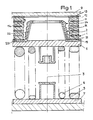
- the device comprises an elastic ring 1 made of elastomer having a laminated or sandwich structure. It is mounted in series with helical springs 4, 5. The load is supported by a support plate 9 on the ring 1.
- the elastomer ring 1 and the helical springs are centered on a same vertical axis 3 along which an axial compression load is exerted.
- the ring 1 is supported on the springs 4 and 5 by means of an upper support cup 6.
- the helical springs are supported on a lower support cup 7.
- the elastomer ring 1 has terminal straight sections which are adhered to two rigid frames 13 and 15.
- the upper frame 13 is integral with the support plate 9 for example of a railway body.
- the lower frame 15 is centered so as to be immobilized horizontally on the upper cup 6.
- the ring comprises intermediate metal rings 11 which extend horizontally at different heights in the thickness of the elastomer. These intermediate rings 11 are preferably arranged at substantially equal intervals between the end reinforcements and they are adhered to the elastomer 12.
- the surface 14 of the bore of the ring is made of elastomer and has a generally cylindrical shape.
- the device has, at the center of the bore of the ring 1, a central stop 2 whose outer surface 24 is separated by a non-zero and finite distance from the surface 14 of the bore of the ring 1.
- the distance measured horizontally increases from bottom to top so that the maximum deflection is on the upper side.
- the central stop 2 is formed by an elastomer cushion 21 adhered to the external surface of a central metal mandrel 22.
- This mandrel has a central part of revolution (cylindrical or frustoconical) on which the cushion is adhered. This part is integral with an annular collar 221 which is immobilized on the upper support cup 6.
- the lower frame 15 of the ring 1 is centered so as to be immobilized horizontally on top of the collar 221.
- the cushion 21 has the form of a sleeve which envelops the mandrel 22.
- the outer surface 24 of the cushion 21 is shaped so as to form with the cylindrical bore of the ring an annular space whose horizontal section increases from bottom to top.
- Intermediate rings 11 located at the height of the central stop 2 each have a bore whose diameter is greater than the diameter of the bore of the ring so that the bores of the rings considered are embedded in the mass of the elastomer.
- the external surface 24 of the central stop 2 and the surface 14 of the bore of the ring 1 form waves of revolution around the axis 3.
- the height of the central stop 2 is less than the height of the ring 1.
- the elastomer cushion 21 forms a buffer at the upper part of the stop so as to constitute an axial elastic stop.
- annular membrane 81 closes the space between the stop 1 and the ring 2 so as to form a chamber 82.
- This chamber 82 contains a fluid.
- FIG. 3 gives the variation of the horizontal deflection as a function of the horizontal force for the assembly constituted by the helical springs, the ring and the stop (curve 1).
- the ring 1 and the central stop 2 can be molded together or separately.
- the elastomer of the ring could be adhered directly to the upper cup of the spring or to the collar 221.
- the outer surface of the stop could be made of polyamide or another plastic material.
Landscapes
- Engineering & Computer Science (AREA)
- Mechanical Engineering (AREA)
- General Engineering & Computer Science (AREA)
- Springs (AREA)
- Vibration Prevention Devices (AREA)
Claims (10)
Applications Claiming Priority (2)
| Application Number | Priority Date | Filing Date | Title |
|---|---|---|---|
| FR8402810A FR2560322B1 (fr) | 1984-02-24 | 1984-02-24 | Dispositif d'appui elastique |
| FR8402810 | 1984-02-24 |
Publications (2)
| Publication Number | Publication Date |
|---|---|
| EP0155209A1 EP0155209A1 (de) | 1985-09-18 |
| EP0155209B1 true EP0155209B1 (de) | 1988-07-27 |
Family
ID=9301352
Family Applications (1)
| Application Number | Title | Priority Date | Filing Date |
|---|---|---|---|
| EP85400312A Expired EP0155209B1 (de) | 1984-02-24 | 1985-02-21 | Elastische Stützvorrichtung |
Country Status (5)
| Country | Link |
|---|---|
| US (1) | US4630807A (de) |
| EP (1) | EP0155209B1 (de) |
| CA (1) | CA1240207A (de) |
| DE (1) | DE3564016D1 (de) |
| FR (1) | FR2560322B1 (de) |
Cited By (1)
| Publication number | Priority date | Publication date | Assignee | Title |
|---|---|---|---|---|
| RU2256572C1 (ru) * | 2003-12-24 | 2005-07-20 | Открытое акционерное общество "Крюковский вагоностроительный завод" (ОАО "КВСЗ") | Тележка пассажирского вагона |
Families Citing this family (11)
| Publication number | Priority date | Publication date | Assignee | Title |
|---|---|---|---|---|
| DE3833182A1 (de) * | 1988-09-30 | 1990-04-05 | Freudenberg Carl Fa | Gummilager |
| DE3840156A1 (de) * | 1988-11-29 | 1990-05-31 | Freudenberg Carl Fa | Elastisches lager fuer einen koerper |
| US5287027A (en) * | 1991-11-01 | 1994-02-15 | Fmc Corporation | Electromagnetic drive for use with vibratory conveyors |
| US5183137A (en) * | 1991-12-20 | 1993-02-02 | Lord Corporation | Dual-rate surface effect dampers |
| JP3526117B2 (ja) * | 1994-11-07 | 2004-05-10 | 株式会社小松製作所 | 液体封入サスペンション |
| GB9924816D0 (en) * | 1999-10-21 | 1999-12-22 | Powell Duffryn Standard Ltd | Primary suspension for a rail vehicle |
| JP2003524127A (ja) * | 2000-02-23 | 2003-08-12 | ヴァコ アーファウエス ゲーエムベーハー | 横方向荷重バネ |
| FR2806452B1 (fr) * | 2000-03-20 | 2002-05-03 | Hutchinson | Amortisseur de vibrations notamment pour rotor d'helicoptere |
| FR2960844B1 (fr) | 2010-06-08 | 2012-07-06 | Hutchinson | Sommier basculant et suspension secondaire le comportant |
| RU193276U1 (ru) * | 2019-08-05 | 2019-10-22 | Акционерное общество "Научно-производственная корпорация "Уралвагонзавод" имени Ф.Э. Дзержинского" | Надрессорная балка с износостойкой защитой подпятника |
| RU196132U1 (ru) * | 2019-08-05 | 2020-02-18 | Акционерное общество "Научно-производственная корпорация "Уралвагонзавод имени Ф.Э.Дзержинского" | Надрессорная балка с износостойкой защитой подпятника |
Family Cites Families (9)
| Publication number | Priority date | Publication date | Assignee | Title |
|---|---|---|---|---|
| US36498A (en) * | 1862-09-23 | Improvement in air-springs | ||
| FR617246A (fr) * | 1925-10-08 | 1927-02-16 | Amortisseur | |
| US2573108A (en) * | 1947-07-03 | 1951-10-30 | Transit Res Corp | Rail truck suspension |
| BE556892A (de) * | 1956-06-25 | |||
| US3118659A (en) * | 1960-02-09 | 1964-01-21 | Luxembourg Brev Participations | Compression springs made of an elastomer |
| GB918661A (en) * | 1960-04-08 | 1963-02-13 | Gen Electric Co Ltd | Improvements in or relating to anti-vibration mountings |
| FR1255804A (fr) * | 1960-04-30 | 1961-03-10 | Hansens Gummi & Packungswerke | Suspension élastique pour véhicules, notamment pour véhicules sur rails |
| FR2354229A1 (fr) * | 1976-06-11 | 1978-01-06 | Kleber Colombes | Suspension ferroviaire |
| FR2363469A1 (fr) * | 1976-08-31 | 1978-03-31 | Soule Ets Ind | Bogie pour voitures ferroviaires |
-
1984
- 1984-02-24 FR FR8402810A patent/FR2560322B1/fr not_active Expired
-
1985
- 1985-02-14 CA CA000474313A patent/CA1240207A/fr not_active Expired
- 1985-02-15 US US06/702,028 patent/US4630807A/en not_active Expired - Fee Related
- 1985-02-21 EP EP85400312A patent/EP0155209B1/de not_active Expired
- 1985-02-21 DE DE8585400312T patent/DE3564016D1/de not_active Expired
Cited By (1)
| Publication number | Priority date | Publication date | Assignee | Title |
|---|---|---|---|---|
| RU2256572C1 (ru) * | 2003-12-24 | 2005-07-20 | Открытое акционерное общество "Крюковский вагоностроительный завод" (ОАО "КВСЗ") | Тележка пассажирского вагона |
Also Published As
| Publication number | Publication date |
|---|---|
| DE3564016D1 (en) | 1988-09-01 |
| FR2560322A1 (fr) | 1985-08-30 |
| EP0155209A1 (de) | 1985-09-18 |
| CA1240207A (fr) | 1988-08-09 |
| FR2560322B1 (fr) | 1986-06-20 |
| US4630807A (en) | 1986-12-23 |
Similar Documents
| Publication | Publication Date | Title |
|---|---|---|
| EP0155209B1 (de) | Elastische Stützvorrichtung | |
| EP0943062B1 (de) | Fahrzeugradaufhängung mit einer feder, die zur veränderung der steifigkeitskurve mit einer flexiblen verstärkung kombiniert ist | |
| EP0596787B1 (de) | Verbesserungen für hydraulische Antivibrationslagen | |
| EP0126006B1 (de) | Verbindungsvorrichtung zwischen dem Aufbau eines Fahrzeuges und einem Aufhängungsbein | |
| EP0191703B1 (de) | Änderungen an hydraulischen Antischwingungslagern | |
| EP1217249B1 (de) | Schwingungsdämpfendes Lager und Kraftfahrzeug mit einem solchen Lager | |
| EP1301733B1 (de) | Hubbegrenzung für einen stossdämpfer eines kraftfahrzeuges und herstellverfahren dafür | |
| FR2812362A1 (fr) | Support antivibratoire hydraulique et son procede de fabrication | |
| EP0410896A1 (de) | Verbesserungen an hydraulischen Schwingungsdämpfern | |
| EP0667466A1 (de) | Aufhängungselement zur Montage zwischen zwei Konstruktionsteilen insbesondere einem Container und einer Plattform | |
| FR2626947A1 (fr) | Manchonnage elastique a remplissage de fluide comportant un corps elastique pre-comprime radialement vers l'interieur | |
| FR2699123A1 (fr) | Amortisseur de vibrations pour véhicules automobiles. | |
| EP0225227B2 (de) | Änderungen an hydraulischen Anti-Schwingungslagern | |
| EP0255434A1 (de) | Hydraulische Dämpfungslager | |
| EP0511907B1 (de) | Verbesserungen an hydraulischer Antischwingungsvorrichtungen | |
| EP2282076B1 (de) | Schwingungsdämpfervorrichtung für ein Fahrzeug, und eine solche Vorrichtung umfassendes Fahrzeug | |
| FR2604231A1 (fr) | Support hydro-elastique, notamment pour la suspension d'un moteur de vehicule automobile. | |
| EP1378682A1 (de) | Hydroelastisches axialwirkendes Gelenk | |
| CH577126A5 (en) | Vibration damping isolating mount for engines - are similar are effective in three orthogonal planes and have silicone inside domed cover | |
| FR2820180A1 (fr) | Ressort pneumatique | |
| FR2624234A1 (fr) | Ressort a douille en caoutchouc | |
| FR2645802A1 (fr) | Train arriere de suspension de vehicule automobile | |
| EP1293701B1 (de) | Schwingungsdämpfendes Lager und Schwingungsdämpfungseinrichtung mit solchem Lager | |
| EP1508722B1 (de) | Befestigung mit Luftfeder, insbesondere für eine Radaufhängung eines Kraftfahrzeugs, und Kraftfahrzeug mit einer solchen Befestigung | |
| FR2699245A1 (fr) | Ressort de suspension hélicoïdal à flexibilité variable. |
Legal Events
| Date | Code | Title | Description |
|---|---|---|---|
| PUAI | Public reference made under article 153(3) epc to a published international application that has entered the european phase |
Free format text: ORIGINAL CODE: 0009012 |
|
| AK | Designated contracting states |
Designated state(s): BE DE FR GB IT |
|
| 17P | Request for examination filed |
Effective date: 19860211 |
|
| 17Q | First examination report despatched |
Effective date: 19870224 |
|
| GRAA | (expected) grant |
Free format text: ORIGINAL CODE: 0009210 |
|
| AK | Designated contracting states |
Kind code of ref document: B1 Designated state(s): BE DE FR GB IT |
|
| GBT | Gb: translation of ep patent filed (gb section 77(6)(a)/1977) | ||
| REF | Corresponds to: |
Ref document number: 3564016 Country of ref document: DE Date of ref document: 19880901 |
|
| ITF | It: translation for a ep patent filed | ||
| PLBE | No opposition filed within time limit |
Free format text: ORIGINAL CODE: 0009261 |
|
| STAA | Information on the status of an ep patent application or granted ep patent |
Free format text: STATUS: NO OPPOSITION FILED WITHIN TIME LIMIT |
|
| 26N | No opposition filed | ||
| ITTA | It: last paid annual fee | ||
| PGFP | Annual fee paid to national office [announced via postgrant information from national office to epo] |
Ref country code: GB Payment date: 19941223 Year of fee payment: 11 |
|
| PGFP | Annual fee paid to national office [announced via postgrant information from national office to epo] |
Ref country code: FR Payment date: 19941230 Year of fee payment: 11 |
|
| PGFP | Annual fee paid to national office [announced via postgrant information from national office to epo] |
Ref country code: BE Payment date: 19950208 Year of fee payment: 11 |
|
| PGFP | Annual fee paid to national office [announced via postgrant information from national office to epo] |
Ref country code: DE Payment date: 19950221 Year of fee payment: 11 |
|
| PG25 | Lapsed in a contracting state [announced via postgrant information from national office to epo] |
Ref country code: GB Effective date: 19960221 |
|
| PG25 | Lapsed in a contracting state [announced via postgrant information from national office to epo] |
Ref country code: BE Effective date: 19960228 |
|
| BERE | Be: lapsed |
Owner name: SOC. M T E S.A. Effective date: 19960228 |
|
| GBPC | Gb: european patent ceased through non-payment of renewal fee |
Effective date: 19960221 |
|
| PG25 | Lapsed in a contracting state [announced via postgrant information from national office to epo] |
Ref country code: FR Effective date: 19961031 |
|
| PG25 | Lapsed in a contracting state [announced via postgrant information from national office to epo] |
Ref country code: DE Effective date: 19961101 |
|
| REG | Reference to a national code |
Ref country code: FR Ref legal event code: ST |