EP0155218A2 - Anreissmaschine mit Impulsservosteuerung,insbesondere für die Bearbeitung von Glaskörpern - Google Patents
Anreissmaschine mit Impulsservosteuerung,insbesondere für die Bearbeitung von Glaskörpern Download PDFInfo
- Publication number
- EP0155218A2 EP0155218A2 EP85400498A EP85400498A EP0155218A2 EP 0155218 A2 EP0155218 A2 EP 0155218A2 EP 85400498 A EP85400498 A EP 85400498A EP 85400498 A EP85400498 A EP 85400498A EP 0155218 A2 EP0155218 A2 EP 0155218A2
- Authority
- EP
- European Patent Office
- Prior art keywords
- servo
- circuit
- linear
- motors
- control
- Prior art date
- Legal status (The legal status is an assumption and is not a legal conclusion. Google has not performed a legal analysis and makes no representation as to the accuracy of the status listed.)
- Granted
Links
Images

Classifications
-
- C—CHEMISTRY; METALLURGY
- C03—GLASS; MINERAL OR SLAG WOOL
- C03B—MANUFACTURE, SHAPING, OR SUPPLEMENTARY PROCESSES
- C03B33/00—Severing cooled glass
- C03B33/02—Cutting or splitting sheet glass or ribbons; Apparatus or machines therefor
- C03B33/04—Cutting or splitting in curves, especially for making spectacle lenses
-
- B—PERFORMING OPERATIONS; TRANSPORTING
- B24—GRINDING; POLISHING
- B24B—MACHINES, DEVICES, OR PROCESSES FOR GRINDING OR POLISHING; DRESSING OR CONDITIONING OF ABRADING SURFACES; FEEDING OF GRINDING, POLISHING, OR LAPPING AGENTS
- B24B17/00—Special adaptations of machines or devices for grinding controlled by patterns, drawings, magnetic tapes or the like; Accessories therefor
- B24B17/10—Special adaptations of machines or devices for grinding controlled by patterns, drawings, magnetic tapes or the like; Accessories therefor involving electrical transmission means only, e.g. controlled by magnetic tape
-
- B—PERFORMING OPERATIONS; TRANSPORTING
- B24—GRINDING; POLISHING
- B24B—MACHINES, DEVICES, OR PROCESSES FOR GRINDING OR POLISHING; DRESSING OR CONDITIONING OF ABRADING SURFACES; FEEDING OF GRINDING, POLISHING, OR LAPPING AGENTS
- B24B9/00—Machines or devices designed for grinding edges or bevels on work or for removing burrs; Accessories therefor
- B24B9/02—Machines or devices designed for grinding edges or bevels on work or for removing burrs; Accessories therefor characterised by a special design with respect to properties of materials specific to articles to be ground
- B24B9/06—Machines or devices designed for grinding edges or bevels on work or for removing burrs; Accessories therefor characterised by a special design with respect to properties of materials specific to articles to be ground of non-metallic inorganic material, e.g. stone, ceramics, porcelain
- B24B9/08—Machines or devices designed for grinding edges or bevels on work or for removing burrs; Accessories therefor characterised by a special design with respect to properties of materials specific to articles to be ground of non-metallic inorganic material, e.g. stone, ceramics, porcelain of glass
- B24B9/10—Machines or devices designed for grinding edges or bevels on work or for removing burrs; Accessories therefor characterised by a special design with respect to properties of materials specific to articles to be ground of non-metallic inorganic material, e.g. stone, ceramics, porcelain of glass of plate glass
-
- G—PHYSICS
- G05—CONTROLLING; REGULATING
- G05B—CONTROL OR REGULATING SYSTEMS IN GENERAL; FUNCTIONAL ELEMENTS OF SUCH SYSTEMS; MONITORING OR TESTING ARRANGEMENTS FOR SUCH SYSTEMS OR ELEMENTS
- G05B19/00—Program-control systems
- G05B19/02—Program-control systems electric
- G05B19/18—Numerical control [NC], i.e. automatically operating machines, in particular machine tools, e.g. in a manufacturing environment, so as to execute positioning, movement or co-ordinated operations by means of program data in numerical form
- G05B19/19—Numerical control [NC], i.e. automatically operating machines, in particular machine tools, e.g. in a manufacturing environment, so as to execute positioning, movement or co-ordinated operations by means of program data in numerical form characterised by positioning or contouring control systems, e.g. to control position from one programmed point to another or to control movement along a programmed continuous path
- G05B19/21—Numerical control [NC], i.e. automatically operating machines, in particular machine tools, e.g. in a manufacturing environment, so as to execute positioning, movement or co-ordinated operations by means of program data in numerical form characterised by positioning or contouring control systems, e.g. to control position from one programmed point to another or to control movement along a programmed continuous path using an incremental digital measuring device
- G05B19/25—Numerical control [NC], i.e. automatically operating machines, in particular machine tools, e.g. in a manufacturing environment, so as to execute positioning, movement or co-ordinated operations by means of program data in numerical form characterised by positioning or contouring control systems, e.g. to control position from one programmed point to another or to control movement along a programmed continuous path using an incremental digital measuring device for continuous-path control
- G05B19/251—Numerical control [NC], i.e. automatically operating machines, in particular machine tools, e.g. in a manufacturing environment, so as to execute positioning, movement or co-ordinated operations by means of program data in numerical form characterised by positioning or contouring control systems, e.g. to control position from one programmed point to another or to control movement along a programmed continuous path using an incremental digital measuring device for continuous-path control the positional error is used to control continuously the servomotor according to its magnitude
- G05B19/253—Numerical control [NC], i.e. automatically operating machines, in particular machine tools, e.g. in a manufacturing environment, so as to execute positioning, movement or co-ordinated operations by means of program data in numerical form characterised by positioning or contouring control systems, e.g. to control position from one programmed point to another or to control movement along a programmed continuous path using an incremental digital measuring device for continuous-path control the positional error is used to control continuously the servomotor according to its magnitude with speed feedback only
Definitions
- the invention relates to servo-mechanisms and, in particular, it aims to control the movement of movable members along an axis, in particular on machines operating in Cartesian coordinates. It equips these materials with a drive device which can be controlled with good precision and at high speed without its parts being subjected to any mechanical wear altering its quality.
- This device is particularly suitable for use on machines requiring regulation of high sensitivity and extremely short response times, such as tracer machines with numerical control with cross-braced carriage intended for working with glass volumes, in particular for cutting or grinding their edges.
- a microprocessor controls the movement of the carriage from a memory containing a movement program by acting on a servo-regulator supplied by repeaters of the actual position and speed values; this controls, by means of an amplifier having a final stage with power transistors or thyristors, the supply of the motors, which one endeavors to equip, in parallel on their windings, with a limiter of induced voltages, by filtering the current pulses, or even by electrically short-circuiting these windings during the breaks which separate them.
- the invention provides an alternating current control circuit by pulse width modulation suitable for controlling and regulating the movement of asynchronous motors, in particular linear motors, circuit provided, in parallel on the windings of these motors, d '' an induced voltage limiter which includes a switching transistor controlled by the modulator, this shortens electrically these windings during the breaks separating the current pulses: their self-induction currents then circulate in a closed circuit , maintaining approximately the magnetic field of the motor; conversely, the voltage spikes induced by the constant variation of the magnetic field under the effect of the clocked command of the modulator are greatly reduced as well as their harmful consequences; in a way, this control circuit works like an amplitude modulation circuit.
- FIG. 1 is, by way of example, that of a three-phase asynchronous motor connected in a triangle,
- the desired setpoint is sent by a setpoint generator 1 to a pulse duration modulator 2 which regulates through a power stage the supply of the winding 3 of the motor.
- the setpoint generator can be provided with an input of actual values and consequently deliver to the modulator 2 a corrected signal. Naturally, it can also obey a programmed memory: such a command is suitable, for example, as a position system for the most diverse applications. Since known control and regulation devices can be used for this purpose, the present description is limited to detailing the construction of the power stage.
- the modulator 2 delivers, in a known manner to the power amplifier, a signal modulated in discrete values or pulses whose width or duration are functions of the instantaneous values of the nominal quantity predetermined by generator 1. It thus acts on the current / cutoff ratio of the three-phase supply voltage.
- the power amplifier comprises a final stage with semiconductors, power transistors or thyristor switches "GTO".
- GTO thyristor switches
- the transistors concerned block or are turned on at the rate of the current / cutoff ratio set by the modulator 2; they therefore control or regulate in the desired direction the current supply of the winding 3.
- a varistor 8 resistance whose value is a function of the voltage, and an RC circuit consisting of a resistor 9 and a capacitor 10 are arranged in parallel on each of the pairs of transistors to erase the voltage spikes which could damage them.
- An additional stage is provided to limit the voltage spikes induced by the permanent clocked control of the power amplifier and which disturb the switching transistors.
- This stage comprises an RC circuit constituted by the resistor 20, the capacitor 21 and a load resistor 22 as well as the associated rectifiers 23, finally a switching transistor 24.
- the base of this transistor is logically connected to the pulse modulator 2 by through the OR circuit 25 and the NOT circuit 26; a separator 27 is interposed between the latter and the transistor 24.
- This command makes the transistor 24 conductive when the eight phase switching transistors are blocked, that is to say during the breaks between current pulses; also, under the effect of 1 self-induction of the winding, the magnetic field of the motor is almost preserved during these cuts. This arrangement allows the regulation to behave more or less like an amplitude regulation.
- this control circuit presupposes that of asynchronous motors whose rotor has an increased resistance, in particular for asynchronous motors with short-circuited rotor; there are similarly asynchronous linear motors with high resistance secondary, so that the circuit according to the invention also makes it very advantageous to enslave such linear motors and to equip them with tracer devices.
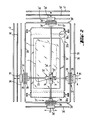
- FIG. 2 The mechanical constitution and the most important elements of the drive mechanism of the tool are shown diagrammatically in FIG. 2 with reference to the cutting of glass volumes on primitives inside a production line.
- the cutting line L is drawn there according to the program stored with the aid of a cutting tool 31 mounted on a crossover carriage 32.
- This consists of the assembly of two superimposed housings 33 and 33 ', the first sliding by means of ball circulation bearings on the shaft 34 in the direction of coordinates indicated by the double arrow Y, the second sliding likewise on the shaft 34 'in the " direction of coordinates indicated by the double arrow X.
- the shaft 34, along which the carriage 32 moves in the direction Y but which simultaneously fixes its position in the direction X is mounted on slides 35 circulating on either side of the work surface, along rails carriers 36, via other ball circulation bearings.
- a double linear motor the primary of which comprises two three-phase inductors 37.
- Each of these inductors mounted respectively on the side of each of the sliders 35, has two cores 38 in the form of combs directed towards each other, in the grooves of which are placed its windings between which passes the secondary, consisting of a fixed rail 39 formed of an electrically good conductive metal such as copper.
- the tracing system further comprises, to serve as a repeater of the effective value of the position, a binary pulse generator 40 disposed along the corresponding path and, to determine the actual value of the speed, a linear potentiometer 41 disposed parallel to this generator.
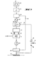
- the operation of the entire tracing system will be explained, for one of the axes, with reference to FIG. 3.
- the command relating to the other axis has an identical constitution.
- the movement program corresponding to the desired path is stored on a magnetic tape 42 and a cassette rewinder 43 introduces it into the working memory of the microprocessor 44.
- the movement orders arrive in the form of set values in the progressive-regressive differential counter 45 which, via the line 46, also receives the movement pulses actually emitted by the generator 40 position repeater, rectangular pulses 90 ° out of phase so as to identify forward and backward movements.
- the counter 45 thus produces a difference signal by difference which the digital-analog converter 47, connected downstream, converts to an analog reference voltage.
- This voltage is sent via line 48 to servo-regulator 1, which receives in parallel, via of line 49, a voltage representative of the effective speed of movement: the latter is produced by the differentiating circuit consisting of the capacity 50, the resistor 51 and the operational amplifier 52 which translates the variation over time of the voltage taken from the linear potentiometer 41.
- the tachometric repeater described also has, compared to other types of repeater, using for example a digital linear generator downstream of which a frequency / voltage converter would be connected, the advantage that the actual value of the voltage delivered is absolutely free of harmonics which is extremely advantageous, especially at low travel speeds.
- the servo-regulator 1 comparing the setpoint value and the actual value, controls, as has been said, the pulse duration modulator 2 which then cuts the instantaneous values of its continuous modulated voltage into discrete values, for example at the rate of 1 kHz and, acting on the power amplifier 4, via the line 6p for the feed movements of the carriage and the line 6r for its feed movements, adjusts according to this setpoint voltage the width, that is to say the duration of the pulses of the three-phase supply voltage received from this amplifier by the inductors 37 of the linear motor.
- the regulator described behaves much better than a regulator operating by phase cutting and makes it possible to build a tracer machine with linear motor having a high sensitivity and a speed of regulation.
Landscapes
- Engineering & Computer Science (AREA)
- Chemical & Material Sciences (AREA)
- Mechanical Engineering (AREA)
- Physics & Mathematics (AREA)
- General Physics & Mathematics (AREA)
- Automation & Control Theory (AREA)
- Manufacturing & Machinery (AREA)
- Materials Engineering (AREA)
- Organic Chemistry (AREA)
- Human Computer Interaction (AREA)
- Ceramic Engineering (AREA)
- Inorganic Chemistry (AREA)
- Control Of Multiple Motors (AREA)
- Control Of Linear Motors (AREA)
Priority Applications (1)
| Application Number | Priority Date | Filing Date | Title |
|---|---|---|---|
| AT85400498T ATE50385T1 (de) | 1984-03-14 | 1985-03-14 | Anreissmaschine mit impulsservosteuerung,insbesondere fuer die bearbeitung von glaskoerpern. |
Applications Claiming Priority (4)
| Application Number | Priority Date | Filing Date | Title |
|---|---|---|---|
| DE3409300 | 1984-03-14 | ||
| DE19843409299 DE3409299C2 (de) | 1984-03-14 | 1984-03-14 | Ein- oder mehrphasiger Wechselstromsteller mit Impulsbreitensteuerung |
| DE19843409300 DE3409300C1 (de) | 1984-03-14 | 1984-03-14 | Kreuzschlittenmaschine mit numerischer Bahnsteuerung für die Bearbeitung von Glasscheiben |
| DE3409299 | 1984-03-14 |
Publications (3)
| Publication Number | Publication Date |
|---|---|
| EP0155218A2 true EP0155218A2 (de) | 1985-09-18 |
| EP0155218A3 EP0155218A3 (en) | 1986-01-02 |
| EP0155218B1 EP0155218B1 (de) | 1990-02-07 |
Family
ID=25819325
Family Applications (1)
| Application Number | Title | Priority Date | Filing Date |
|---|---|---|---|
| EP85400498A Expired - Lifetime EP0155218B1 (de) | 1984-03-14 | 1985-03-14 | Anreissmaschine mit Impulsservosteuerung,insbesondere für die Bearbeitung von Glaskörpern |
Country Status (3)
| Country | Link |
|---|---|
| EP (1) | EP0155218B1 (de) |
| DE (1) | DE3576023D1 (de) |
| WO (1) | WO1985004292A1 (de) |
Cited By (2)
| Publication number | Priority date | Publication date | Assignee | Title |
|---|---|---|---|---|
| EP0437288A3 (en) * | 1987-11-06 | 1991-08-07 | Tamglass Oy | Apparatus for cutting and grinding glass blanks |
| EP0484674A3 (en) * | 1990-10-05 | 1992-08-05 | Intermac S.R.L. | Process for the automatic machining of edges of glass plates and apparatus for carrying out said process |
Families Citing this family (2)
| Publication number | Priority date | Publication date | Assignee | Title |
|---|---|---|---|---|
| CA2169836A1 (en) * | 1993-08-20 | 1995-03-02 | Gunnar Wiklund | Circuit for speed control for a one-phase or three-phase motor |
| WO2016085361A1 (en) | 2014-11-24 | 2016-06-02 | Teixeira E Silva Cardoso Paulo Alexandre | Single dose capsole, system and process for preparing edible products using said single dose capsule |
Family Cites Families (6)
| Publication number | Priority date | Publication date | Assignee | Title |
|---|---|---|---|---|
| DD53786A (de) * | ||||
| US3962613A (en) * | 1973-01-31 | 1976-06-08 | Wer Industrial Division Of Emerson Electric Co. | Polyphase AC motor control |
| DE2646062C3 (de) * | 1976-10-13 | 1979-08-09 | Vereinigte Glaswerke Gmbh, 5100 Aachen | Numerisch gesteuerte Modellschneidemaschine für Glasscheiben |
| DE2731230B1 (de) * | 1977-07-11 | 1978-06-15 | Werner Spreng Maschinen U Werk | Numerisch gesteuerte Flachglas-Schneidemaschine |
| JPS5622595A (en) * | 1979-07-28 | 1981-03-03 | Toshiba Mach Co Ltd | Controller for torque of induction motor |
| WO1982003508A1 (fr) * | 1981-03-31 | 1982-10-14 | Yamamura Sakae | Procede et dispositif de commande d'un moteur a courant alternatif |
-
1985
- 1985-03-14 WO PCT/FR1985/000053 patent/WO1985004292A1/fr not_active Ceased
- 1985-03-14 DE DE8585400498T patent/DE3576023D1/de not_active Expired - Fee Related
- 1985-03-14 EP EP85400498A patent/EP0155218B1/de not_active Expired - Lifetime
Cited By (3)
| Publication number | Priority date | Publication date | Assignee | Title |
|---|---|---|---|---|
| EP0437288A3 (en) * | 1987-11-06 | 1991-08-07 | Tamglass Oy | Apparatus for cutting and grinding glass blanks |
| EP0484674A3 (en) * | 1990-10-05 | 1992-08-05 | Intermac S.R.L. | Process for the automatic machining of edges of glass plates and apparatus for carrying out said process |
| US5216844A (en) * | 1990-10-05 | 1993-06-08 | Intermac S.R.L. | Process for the automatic machining of edges of glass plates and apparatus for carrying out said process |
Also Published As
| Publication number | Publication date |
|---|---|
| DE3576023D1 (de) | 1990-03-15 |
| EP0155218A3 (en) | 1986-01-02 |
| EP0155218B1 (de) | 1990-02-07 |
| WO1985004292A1 (fr) | 1985-09-26 |
Similar Documents
| Publication | Publication Date | Title |
|---|---|---|
| EP0364589B1 (de) | Anordnung zum schalten der verbindung eines dreiphasen-induktionsmotors | |
| EP0346488A1 (de) | Antriebsanordnung und steuerung der spindel einer werkzeugmaschine | |
| EP1213094A3 (de) | Poliervorrichtung mit Verriegelungsfunktion | |
| EP0155218B1 (de) | Anreissmaschine mit Impulsservosteuerung,insbesondere für die Bearbeitung von Glaskörpern | |
| US4589230A (en) | Grinding machine | |
| GB2088592A (en) | Machine tool control | |
| EP0114141A2 (de) | Verfahren zur automatischen Steuerung einer Schleifmaschine mit drehbarem Schleifkopf zum Schleifen von Glasplattenrändern und Vorrichtung zur Anwendung desselben | |
| WO1989007858A1 (fr) | Unite de commande de commutation de la puissance de sortie d'un moteur | |
| EP0168311A2 (de) | Schleifmaschine mit einem Regelkreis zum Positionieren des Werkzeugschlittens | |
| FR2554749A1 (fr) | Dispositif d'avancement pour plusieurs chariots a coulissement longitudinal d'une machine-outil | |
| EP0214300A1 (de) | Vorrichtung zur regelung der geschwindigkeit eines elektromotors | |
| US3560826A (en) | Grinding wheel control system and apparatus | |
| US5224695A (en) | Method and apparatus for feeding documents | |
| JP3079937B2 (ja) | 卓上切断機 | |
| US798391A (en) | Motor-driven machine-tool. | |
| KR920006507B1 (ko) | 와이어 방전 가공장치 | |
| JPS61501485A (ja) | 特にガラス体の加工のための非同期機のパルス自動制御 | |
| US660801A (en) | Electrically-operated-machine-tool. | |
| EP0169108B1 (de) | Geschwindigkeitsregeleinrichtung für einen elektrischen Asynchronmotor | |
| CH662525A5 (fr) | Procede pour reguler les conditions d'etincelage sur une machine a eroder par decharges erosives et dispositif pour sa mise en oeuvre. | |
| US1008593A (en) | Speed-varying device for machine-tools. | |
| US1070638A (en) | Control system for electric motors. | |
| US3812412A (en) | Photoelectric scanning device for flame cutting machines | |
| DE3471451D1 (en) | Method of controlling the service performance of projection form grinding machines | |
| SU1393607A1 (ru) | Устройство дл шлифовани фасонных тел вращени |
Legal Events
| Date | Code | Title | Description |
|---|---|---|---|
| PUAI | Public reference made under article 153(3) epc to a published international application that has entered the european phase |
Free format text: ORIGINAL CODE: 0009012 |
|
| AK | Designated contracting states |
Designated state(s): AT BE CH DE FR GB IT LI LU NL SE |
|
| PUAL | Search report despatched |
Free format text: ORIGINAL CODE: 0009013 |
|
| AK | Designated contracting states |
Designated state(s): AT BE CH DE FR GB IT LI LU NL SE |
|
| 17P | Request for examination filed |
Effective date: 19860203 |
|
| 17Q | First examination report despatched |
Effective date: 19861127 |
|
| R17C | First examination report despatched (corrected) |
Effective date: 19870515 |
|
| GRAA | (expected) grant |
Free format text: ORIGINAL CODE: 0009210 |
|
| RAP1 | Party data changed (applicant data changed or rights of an application transferred) |
Owner name: SAINT-GOBAIN VITRAGE INTERNATIONAL Owner name: VEGLA VEREINIGTE GLASWERKE GMBH |
|
| AK | Designated contracting states |
Kind code of ref document: B1 Designated state(s): AT BE CH DE FR GB IT LI LU NL SE |
|
| REF | Corresponds to: |
Ref document number: 50385 Country of ref document: AT Date of ref document: 19900215 Kind code of ref document: T |
|
| REF | Corresponds to: |
Ref document number: 3576023 Country of ref document: DE Date of ref document: 19900315 |
|
| ITF | It: translation for a ep patent filed | ||
| GBT | Gb: translation of ep patent filed (gb section 77(6)(a)/1977) | ||
| PLBE | No opposition filed within time limit |
Free format text: ORIGINAL CODE: 0009261 |
|
| STAA | Information on the status of an ep patent application or granted ep patent |
Free format text: STATUS: NO OPPOSITION FILED WITHIN TIME LIMIT |
|
| PGFP | Annual fee paid to national office [announced via postgrant information from national office to epo] |
Ref country code: BE Payment date: 19901227 Year of fee payment: 7 |
|
| PGFP | Annual fee paid to national office [announced via postgrant information from national office to epo] |
Ref country code: LU Payment date: 19910102 Year of fee payment: 7 |
|
| PGFP | Annual fee paid to national office [announced via postgrant information from national office to epo] |
Ref country code: SE Payment date: 19910109 Year of fee payment: 7 |
|
| 26N | No opposition filed | ||
| PGFP | Annual fee paid to national office [announced via postgrant information from national office to epo] |
Ref country code: AT Payment date: 19910311 Year of fee payment: 7 |
|
| ITTA | It: last paid annual fee | ||
| PGFP | Annual fee paid to national office [announced via postgrant information from national office to epo] |
Ref country code: NL Payment date: 19910331 Year of fee payment: 7 |
|
| EPTA | Lu: last paid annual fee | ||
| PG25 | Lapsed in a contracting state [announced via postgrant information from national office to epo] |
Ref country code: AT Effective date: 19920314 Ref country code: LU Free format text: LAPSE BECAUSE OF NON-PAYMENT OF DUE FEES Effective date: 19920314 |
|
| PG25 | Lapsed in a contracting state [announced via postgrant information from national office to epo] |
Ref country code: SE Effective date: 19920315 |
|
| PG25 | Lapsed in a contracting state [announced via postgrant information from national office to epo] |
Ref country code: BE Effective date: 19920331 |
|
| BERE | Be: lapsed |
Owner name: VEGLA VEREINIGTE GLAWERKE G.M.B.H. Effective date: 19920331 Owner name: SAINT-GOBAIN VITRAGE INTERNATIONAL Effective date: 19920331 |
|
| PG25 | Lapsed in a contracting state [announced via postgrant information from national office to epo] |
Ref country code: NL Effective date: 19921001 |
|
| NLV4 | Nl: lapsed or anulled due to non-payment of the annual fee | ||
| EUG | Se: european patent has lapsed |
Ref document number: 85400498.3 Effective date: 19921005 |
|
| REG | Reference to a national code |
Ref country code: GB Ref legal event code: IF02 |
|
| PGFP | Annual fee paid to national office [announced via postgrant information from national office to epo] |
Ref country code: DE Payment date: 20020404 Year of fee payment: 18 |
|
| PGFP | Annual fee paid to national office [announced via postgrant information from national office to epo] |
Ref country code: FR Payment date: 20030305 Year of fee payment: 19 |
|
| PGFP | Annual fee paid to national office [announced via postgrant information from national office to epo] |
Ref country code: GB Payment date: 20030312 Year of fee payment: 19 |
|
| PGFP | Annual fee paid to national office [announced via postgrant information from national office to epo] |
Ref country code: CH Payment date: 20030314 Year of fee payment: 19 |
|
| PG25 | Lapsed in a contracting state [announced via postgrant information from national office to epo] |
Ref country code: DE Free format text: LAPSE BECAUSE OF NON-PAYMENT OF DUE FEES Effective date: 20031001 |
|
| PG25 | Lapsed in a contracting state [announced via postgrant information from national office to epo] |
Ref country code: GB Free format text: LAPSE BECAUSE OF NON-PAYMENT OF DUE FEES Effective date: 20040314 |
|
| PG25 | Lapsed in a contracting state [announced via postgrant information from national office to epo] |
Ref country code: LI Free format text: LAPSE BECAUSE OF NON-PAYMENT OF DUE FEES Effective date: 20040331 Ref country code: CH Free format text: LAPSE BECAUSE OF NON-PAYMENT OF DUE FEES Effective date: 20040331 |
|
| GBPC | Gb: european patent ceased through non-payment of renewal fee |
Effective date: 20040314 |
|
| REG | Reference to a national code |
Ref country code: CH Ref legal event code: PL |
|
| PG25 | Lapsed in a contracting state [announced via postgrant information from national office to epo] |
Ref country code: FR Free format text: LAPSE BECAUSE OF NON-PAYMENT OF DUE FEES Effective date: 20041130 |
|
| REG | Reference to a national code |
Ref country code: FR Ref legal event code: ST |
|
| PG25 | Lapsed in a contracting state [announced via postgrant information from national office to epo] |
Ref country code: LU Free format text: LAPSE BECAUSE OF NON-PAYMENT OF DUE FEES Effective date: 19900331 |