EP0155220A2 - Vorgefertigte Zarge für das Ausstatten von Bauöffnungen - Google Patents
Vorgefertigte Zarge für das Ausstatten von Bauöffnungen Download PDFInfo
- Publication number
- EP0155220A2 EP0155220A2 EP85420042A EP85420042A EP0155220A2 EP 0155220 A2 EP0155220 A2 EP 0155220A2 EP 85420042 A EP85420042 A EP 85420042A EP 85420042 A EP85420042 A EP 85420042A EP 0155220 A2 EP0155220 A2 EP 0155220A2
- Authority
- EP
- European Patent Office
- Prior art keywords
- shelf
- recess
- leg
- projecting
- threaded rod
- Prior art date
- Legal status (The legal status is an assumption and is not a legal conclusion. Google has not performed a legal analysis and makes no representation as to the accuracy of the status listed.)
- Withdrawn
Links
Images

Classifications
-
- E—FIXED CONSTRUCTIONS
- E06—DOORS, WINDOWS, SHUTTERS, OR ROLLER BLINDS IN GENERAL; LADDERS
- E06B—FIXED OR MOVABLE CLOSURES FOR OPENINGS IN BUILDINGS, VEHICLES, FENCES OR LIKE ENCLOSURES IN GENERAL, e.g. DOORS, WINDOWS, BLINDS, GATES
- E06B3/00—Window sashes, door leaves, or like elements for closing wall or like openings; Layout of fixed or moving closures, e.g. windows in wall or like openings; Features of rigidly-mounted outer frames relating to the mounting of wing frames
- E06B3/96—Corner joints or edge joints for windows, doors, or the like frames or wings
- E06B3/9632—Corner joints or edge joints for windows, doors, or the like frames or wings between a jamb and the threshold or sill of window or door frames
-
- E—FIXED CONSTRUCTIONS
- E06—DOORS, WINDOWS, SHUTTERS, OR ROLLER BLINDS IN GENERAL; LADDERS
- E06B—FIXED OR MOVABLE CLOSURES FOR OPENINGS IN BUILDINGS, VEHICLES, FENCES OR LIKE ENCLOSURES IN GENERAL, e.g. DOORS, WINDOWS, BLINDS, GATES
- E06B1/00—Border constructions of openings in walls, floors, or ceilings; Frames to be rigidly mounted in such openings
- E06B1/04—Frames for doors, windows, or the like to be fixed in openings
- E06B1/24—Frames of natural stone, concrete, or other stone-like material
-
- E—FIXED CONSTRUCTIONS
- E06—DOORS, WINDOWS, SHUTTERS, OR ROLLER BLINDS IN GENERAL; LADDERS
- E06B—FIXED OR MOVABLE CLOSURES FOR OPENINGS IN BUILDINGS, VEHICLES, FENCES OR LIKE ENCLOSURES IN GENERAL, e.g. DOORS, WINDOWS, BLINDS, GATES
- E06B3/00—Window sashes, door leaves, or like elements for closing wall or like openings; Layout of fixed or moving closures, e.g. windows in wall or like openings; Features of rigidly-mounted outer frames relating to the mounting of wing frames
- E06B3/96—Corner joints or edge joints for windows, doors, or the like frames or wings
- E06B3/9616—Corner joints or edge joints for windows, doors, or the like frames or wings characterised by the sealing at the junction of the frame members
Definitions
- the present invention relates to a prefabricated panel for equipping building openings.
- the prefabricated panels are made of concrete, it is advantageous, for reasons of ease of transport and handling, that they be produced in several independent parts, which can be assembled together when they are mounted inside the opening to be fitted.
- such a table comprises four parts, namely a horizontal lower part or shelf, two vertical legs and a horizontal upper part or lintel.
- each end of a shelf and a leg is achieved by engagement of a threaded rod protruding from each end of the shelf in an opening formed transversely in a leg, near the lower end of this one.
- the connection between the two parts considered is achieved by a nut which, screwed onto the threaded rod, presses the jamb against the shelf.
- each leg has a threaded rod which, projecting vertically from its upper end, is intended to be engaged in an opening that comprises the lintel, with fixing by a nut.
- the present invention aims to remedy these drawbacks.
- the shelf has at each of its ends a central recess opening into its face upper and in its end wall considered, a threaded rod oriented axially to the shelf projecting from the bottom of the recess, while each leg has, at its lower end and in its central area, a projecting portion of smaller dimensions or equal to the dimensions of a recess at one end of the shelf, in order to be able to be engaged therein, a transverse groove being provided in the projecting part of each leg, which opens at the lower end of it ci and is intended to cover the threaded rod protruding from the bottom of the shelf recess.
- each recess formed at one end of a shelf has, seen in cross section, a frustoconical section whose short side is turned downward, while each part projecting from the lower end of a leg has a section of corresponding shape and of height less than that of the shelf recess.
- This shape is interesting because it allows, taking into account the profiled shapes of the projecting part of each leg and the corresponding recess of the shelf, to achieve self-centering of these two elements during the vertical descent movement of the leg. In addition, given the fact that the height of the projecting part of the leg is less than that of the recess, these positioning and assembly elements do not disturb the support of each leg on the shelf.
- this table is equipped with a seal intended to be housed between the lower face of each leg and the upper face of a shelf, having two cutouts ensuring the formation of a tongue capable of folding back in an end recess of the shelf and to be positioned between the walls in contact with the bottom of the shelf recess and the part projecting from the lower part of the leg.
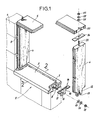
- the table (2) shown in the drawing includes a lower shelf (3), two vertical legs (4) and a upper lintel (5).
- the shelf (3) has a generally traditional shape, in order to have an outer edge projecting from the wall (6) of the building to be equipped. At each of its ends, the shelf (3) has a recess (7) opening into its upper, lower faces and into a lateral face. This recess (7) has a trapezoidal section, the short side of which faces downwards. From the bottom of the recess (7) projects a threaded rod (8), one end of which is embedded inside the shelf.
- Each leg (4) is traditionally equipped with sockets (9) for fixing the shutters and sockets, not shown in the drawing, for fixing a frame (10).
- each leg (4) has a part (12) projecting from its lower end.
- This part (12) has a section of shape corresponding to the section of the recess (7), and of dimensions slightly smaller than those of this recess so as to be able to be engaged therein.
- the height of the part (12) is less than the height of the recess (7) so as not to disturb the support of the leg on the shelf.
- the part (12) has a transverse and central groove (13) intended to come over the threaded rod (8), in the assembled position of the leg relative to the shelf, this groove being of sufficient depth so that its bottom is not in support against the threaded rod (8).
- a seal (14) comprising two cutouts (15) providing a central tongue (16) is interposed between the shelf (3) and each leg, this seal (14) having a part (17) interposed between the contacting faces of the shelf and the jamb, while its tongue (16) is interposed between the bottom of the recess (7) and a side face of the part (12) projecting from the jamb.
- the leg (4) is locked relative to the shelf (3) by means of a nut (18) engaged on the threaded rod (8), with inter position of a bitumen washer (19) and a steel washer (20).
- a threaded rod (22) projects vertically from the upper edge of each leg, intended to be engaged in an opening (23) formed in the lintel (5) with interposition of a seal (24), the fixing being here again obtained using a nut (25) with the interposition of a bitumen washer (26) and a steel washer (27).
- seals (28) facing the interior of the switchboard are provided in the areas of junction between two parts of the latter, shelf-legs and lintel-legs.
- the invention brings a great improvement to the existing technique by providing a prefabricated panel for building openings, the basic elements of which can be transported and handled easily, and the assembly of which is extremely simple and does not requires only little space, limiting as much as possible the oversizing of the openings necessary for positioning and fixing the various elements of the table.
Landscapes
- Engineering & Computer Science (AREA)
- Civil Engineering (AREA)
- Structural Engineering (AREA)
- Furniture Connections (AREA)
- Wing Frames And Configurations (AREA)
Applications Claiming Priority (2)
| Application Number | Priority Date | Filing Date | Title |
|---|---|---|---|
| FR8404319 | 1984-03-12 | ||
| FR8404319A FR2560920B1 (fr) | 1984-03-12 | 1984-03-12 | Tableau prefabrique pour l'equipement d'ouvertures de batiments |
Publications (2)
| Publication Number | Publication Date |
|---|---|
| EP0155220A2 true EP0155220A2 (de) | 1985-09-18 |
| EP0155220A3 EP0155220A3 (de) | 1986-01-02 |
Family
ID=9302251
Family Applications (1)
| Application Number | Title | Priority Date | Filing Date |
|---|---|---|---|
| EP85420042A Withdrawn EP0155220A3 (de) | 1984-03-12 | 1985-03-12 | Vorgefertigte Zarge für das Ausstatten von Bauöffnungen |
Country Status (2)
| Country | Link |
|---|---|
| EP (1) | EP0155220A3 (de) |
| FR (1) | FR2560920B1 (de) |
Family Cites Families (6)
| Publication number | Priority date | Publication date | Assignee | Title |
|---|---|---|---|---|
| DE727246C (de) * | 1937-05-13 | 1942-10-29 | Georg Hoentsch Sen | Eckverbindung fuer Rahmen aus Holz, Metall oder anderen Werkstoffen |
| DE804038C (de) * | 1948-03-24 | 1951-04-16 | Central Cornwall Concrete & Ar | Tuer- oder Fenstereinfassung aus Betonfertigteilen fuer Plattenwaende |
| FR1230877A (fr) * | 1958-07-21 | 1960-09-20 | Erich Reimer Nachf Fa | Encadrement de parement pour fenêtre |
| US3230676A (en) * | 1962-12-04 | 1966-01-25 | Feathertouch Concrete Products | Post-tensioned construction frame |
| NL147506B (nl) * | 1965-06-24 | 1975-10-15 | Lak En Vernisfabrieken Wed Boo | Houtverbinding met een tussenplaat. |
| DE2420688A1 (de) * | 1974-04-29 | 1975-11-06 | Biffar Oskar D | Vorrichtung zum verbinden von rahmenelementen |
-
1984
- 1984-03-12 FR FR8404319A patent/FR2560920B1/fr not_active Expired
-
1985
- 1985-03-12 EP EP85420042A patent/EP0155220A3/de not_active Withdrawn
Also Published As
| Publication number | Publication date |
|---|---|
| EP0155220A3 (de) | 1986-01-02 |
| FR2560920B1 (fr) | 1987-08-21 |
| FR2560920A1 (fr) | 1985-09-13 |
Similar Documents
| Publication | Publication Date | Title |
|---|---|---|
| EP0318537A1 (de) | Vorgefertigtes baupaneel, insbesondere für grufter. | |
| FR2623837A1 (fr) | Revetement de facade | |
| EP0079278A1 (de) | Fenster- oder Türrahmen mit Abflussmöglichkeit für Wasser | |
| EP0412904B1 (de) | Holzumrahmung mit einer Nut für die Verglasung | |
| FR2585401A1 (fr) | Dispositif pour le calage des vitrages isolants sur les menuiseries exterieures | |
| FR2781511A1 (fr) | Abri telescopique | |
| EP0112199B1 (de) | Rahmen in Öffnungen bestehend aus Metallprofilen mit unterbrochenen Wärmebrücken und Pressgerät für das Bearbeiten dieser Profile | |
| FR2560920A1 (fr) | Tableau prefabrique pour l'equipement d'ouvertures de batiments | |
| EP0091894B1 (de) | Halterung für Rinneneinheit eines Daches | |
| CH648090A5 (en) | Prefabricated dressings | |
| EP0133838B1 (de) | Rahmen für die Herstellung von Türen, Fenstern, Wänden und dergleichen | |
| FR2652863A1 (fr) | Dispositif de fixation d'une surface plane, notamment en verre, sur un cadre support. | |
| FR2558875A1 (fr) | Systeme de revetement de parois, telles que des murs ou des facades de batiments, elements d'un tel systeme et procede pour la mise en place de ce systeme | |
| EP0773332A1 (de) | Dichtungsanordnung zwischen den Rahmen von Vorhangfassaden | |
| EP0909866A1 (de) | Wandelement aus einem Profilrahmen und einer Isolierverglasung mit Stufenrand | |
| EP0712970B1 (de) | Fassadenstruktur für Gebaüde oder ähnliche Strukturen | |
| FR2480844A1 (fr) | Dispositif pour assurer le support et la liaison drainante de panneaux | |
| FR3165279A1 (fr) | Garde-corps comprenant une plaque de remplissage en tôle fixée sur des montants et des lisses de remplissage | |
| EP0021876A1 (de) | Vorrichtung zum Feststellen von Türen und Toren | |
| FR2771434A1 (fr) | Procede de montage par l'interieur d'un panneau dans un alveole d'une ossature de support | |
| EP1229179A1 (de) | Unterbrochene Wärmebrücke für metallische Profile | |
| FR2605348A3 (fr) | Serie de profiles metalliques pour fenetres, portes-fenetres, vitrages, ou similaires. | |
| FR2858341A1 (fr) | Ensemble de fixation de cales ou pieces de securite pour panneaux vitres d'une facade a mur rideau | |
| EP1369549A1 (de) | Selbsttragendes Türblatt für ein Kipptor | |
| CH510534A (fr) | Dispositif pour le montage amovible d'un panneau ouvrant |
Legal Events
| Date | Code | Title | Description |
|---|---|---|---|
| PUAI | Public reference made under article 153(3) epc to a published international application that has entered the european phase |
Free format text: ORIGINAL CODE: 0009012 |
|
| AK | Designated contracting states |
Designated state(s): AT BE CH DE GB IT LI LU NL SE |
|
| PUAL | Search report despatched |
Free format text: ORIGINAL CODE: 0009013 |
|
| AK | Designated contracting states |
Designated state(s): AT BE CH DE GB IT LI LU NL SE |
|
| STAA | Information on the status of an ep patent application or granted ep patent |
Free format text: STATUS: THE APPLICATION IS DEEMED TO BE WITHDRAWN |
|
| 18D | Application deemed to be withdrawn |
Effective date: 19860902 |