EP0155256B1 - Voiture de chemin de fer avec dispositif de chauffage et de climatisation - Google Patents
Voiture de chemin de fer avec dispositif de chauffage et de climatisation Download PDFInfo
- Publication number
- EP0155256B1 EP0155256B1 EP19850890020 EP85890020A EP0155256B1 EP 0155256 B1 EP0155256 B1 EP 0155256B1 EP 19850890020 EP19850890020 EP 19850890020 EP 85890020 A EP85890020 A EP 85890020A EP 0155256 B1 EP0155256 B1 EP 0155256B1
- Authority
- EP
- European Patent Office
- Prior art keywords
- hollow frame
- wall
- coach
- compartment
- air
- Prior art date
- Legal status (The legal status is an assumption and is not a legal conclusion. Google has not performed a legal analysis and makes no representation as to the accuracy of the status listed.)
- Expired
Links
Images

Classifications
-
- B—PERFORMING OPERATIONS; TRANSPORTING
- B61—RAILWAYS
- B61D—BODY DETAILS OR KINDS OF RAILWAY VEHICLES
- B61D27/00—Heating, cooling, ventilating, or air-conditioning
- B61D27/0018—Air-conditioning means, i.e. combining at least two of the following ways of treating or supplying air, namely heating, cooling or ventilating
Definitions
- the invention relates to a railway wagon with heating or air conditioning, an air duct running below the lower edge of the compartment windows arranged in the wagon outer wall, from which supply ducts extend to outlet openings at the height of the lower window edges on the one hand and above the upper window edges on the other hand
- supply ducts are delimited to the inside of the wagon by an intermediate wall which also covers at least part of the vertical region of the inside of the outside of the wagon above the air duct and also serves to cover window edges.
- Such an arrangement is known, for example, from AT-B 355618 and, due to the outflow of the heated or air-conditioned air at the lower window edge on the one hand and above the upper window edge on the other hand, enables very uniform and draft-free heating or air conditioning of the wagon compartment.
- the disadvantage here is that the installation of the intermediate wall delimiting the supply ducts to the inside of the wagon is relatively complex, since for a sufficient seal against the inside of the outside of the wagon or against the window edges as well as for maintaining the required distance from this inside to ensure the necessary Cross sections for the air flow must be provided.
- the object of the present invention is to achieve an improvement of the known arrangement, while maintaining the advantages of the known arrangement with regard to the distribution of the inflowing air into the compartment, in such a way that in particular the assembly of the entire arrangement is simplified and a low-noise, optically simple means attractive, closed construction is achieved in particular with regard to the air duct.
- the intermediate wall is designed as a compartment-side boundary of a hollow frame which contains the supply channels and is connected to transfer openings of the air guide channel.
- the supply ducts to the outflow openings are thus formed in the hollow frame independently of the inside of the wagon outer wall, so that this only has to be attached to this inside in a very simple manner when the railway wagons are assembled; there are no more requirements with regard to sealing or maintaining a precise distance, which - while ensuring the optimal function - simplifies assembly work.
- air guiding devices for the flow separation of the supply channels are arranged in the interior of the hollow frame. These air guiding devices can therefore already be provided in this frame, for example in the course of its manufacture, even before the hollow frame is installed in the railway wagon, which does not further burden the assembly work in the railway wagon.
- the air guiding devices are adjustable, e.g. have control devices, in particular flaps, which can be influenced by the regulation of the heating or air conditioning system and which control the free flow cross sections of the supply channels in the hollow frame.
- flaps can be designed, for example, so that once the frame has been installed in the railroad car, they are adjusted once with a view to optimal outflow conditions from the various outflow openings and are no longer adjusted during operation of the heating or air conditioning system. It would also be advantageous to provide an adjustment of these control devices by regulating the heating or air conditioning system.
- the outflow openings arranged at the lower edge of the window which are primarily intended to prevent the windows from fogging up in heating mode, could be closed by closing off the associated supply ducts in cooling mode.
- the hollow frame is made in one piece and can be attached to the inside of the wagon outer wall, since the assembly work is thus limited to setting up and fastening a single component on the inside of the wagon outer wall.
- the frame can be designed as a plastic injection-molded part, which on the one hand enables cost-effective production and on the other hand also brings advantages in connection with thermal insulation and sound insulation.
- the hollow frame is sealed off from the outside of the wagon by means of a seal which also serves to hold and seal the window. All that needs to be done is to attach, connect and seal the frame containing the preassembled window as a preassembled component during the final assembly of the wagon at a corresponding point on the inside of the outer wall.
- the hollow frame consists of several parts, each of which forms a separate feed channel leading to an outflow opening or a group of outflow openings.
- each of the outflow openings provided to have its own adjoining frame parts, the manufacture of which is simplified compared to a single component which covers the entire compartment wall, and which is nevertheless from the compartment seen form a single, practically continuous partition wall to the inside of the compartment.
- a further embodiment of the invention provides that the hollow frame forms a preassembled structural unit together with at least part of the air duct running in the compartment. This simplifies the assembly of the parts of the air duct in each compartment in a very simple manner, since the actual air duct can be preassembled with the hollow frame containing the inlet ducts and thus only the connections to the other parts of the air duct during the actual assembly in the compartment Heating or air conditioning must be manufactured.
- the structural unit in the area of the air duct has connection parts on both sides which, in the installed state, seal in the compartment against connection openings provided there.
- connection parts on both sides which, in the installed state, seal in the compartment against connection openings provided there.
- seals, fastening devices such as screws, fastening brackets or the like
- other additional parts which enable assembly and provide a secure seal can be attached.
- the structural unit is designed as a one-piece plastic injection-molded part. This eliminates the need for pre-assembly, and due to the lightness and the heat-insulating properties of plastic, there are further advantages.
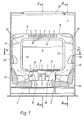
- the compartment 1 shown in FIG. 1 of a railway wagon, not shown, is connected via an air duct 2 to a heating or air conditioning system, also not shown, which is usually arranged, for example, below the wagon floor and supplies heated or conditioned air to the compartment 1.
- a heating or air conditioning system also not shown, which is usually arranged, for example, below the wagon floor and supplies heated or conditioned air to the compartment 1.
- the air duct 2 is arranged below the lower edge 3 of a window 5 embedded in the outer wall 4 of the wagon along the window-side compartment wall, and is via supply ducts 6, 7, 8 with outflow openings 9, 10 at the height of the lower window edge 3 on the one hand and above the upper one Window edge 11 connected on the other hand.
- the supply ducts 6, 7, 8 are delimited to the inside of the wagon by an intermediate wall 14 which also serves to cover the window edges 3, 11, 12, 13 and covers at least part of the vertical area of the inside of the wagon outer wall 4 above the air duct 2, which serves as a compartment Boundary of a hollow frame 15 is formed, which receives the supply channels 6, 7, 8 and is connected to transfer openings 16 (Fig.2) of the air duct 2.
- This hollow frame has air guiding devices 17 for the flow separation of the supply ducts 6, 7, 8, the free flow cross sections being able to be controlled via adjustable flaps 18 or similar control devices and being adjusted, for example, depending on the regulation of the heating or air conditioning system.
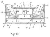
- the feed channels 6 ', 7', 8 ' are also towards the inside of the wagon from at least part of the vertical also serving to cover the window edges Limited area of the inside of the outer wall 4 of the wagon above the intermediate wall 14 covering the air duct 2, which is designed as a compartment-side boundary of a hollow frame 15 which forms a preassembled unit 32 with the air duct.
- the hollow frame 15 can also have air guiding devices 17 'for the flow separation of the supply ducts 6 ' , 7 ', 8 ' , adjustable flaps 18 'or similar control devices also being provided.
- the structural unit 32 is in one piece, for example as a plastic injection-molded part, and also has the outflow openings 9 on the lower window edge and not shown here, those on the upper window edge and the lateral window edges.
- the structural unit 32 is divided into a hollow frame 15 and air duct 2, it is also possible to manufacture the individual components from suitable materials, for example sheet metal on the one hand and plastic on the other hand.
- connection parts 33 on both sides, which in the installed state of the assembly in compartment 1 against it - for example in the form of connecting pieces or the like. Seal the intended connection openings 34. Any seals, fasteners, etc. to be provided during assembly are not shown.
- the hollow frame 15 or the structural unit 32 are made in one piece, for example as injection-molded plastic parts, and also have the outflow openings 9 (lower window edge) and 10 (upper window edge). It is also possible to design the frame as a pressed sheet metal part and to provide it with a preferably noise or heat-insulating coating at least on the inside of the compartment. In addition to this, in both cases, outflow openings could also be provided in the area of the lateral window edges 12, 13, each of which would be aligned with the opposite window edge, since, owing to the relatively large cross-section of the supply ducts available, only low flow velocities have to be provided and therefore no annoyance to the respective ones at the window seat opposite to seated travelers is to be feared. Additional air guidance devices or control devices could also be provided for these outflow openings, if necessary.
- the hollow frame 15 can have an inlet opening 19 for the supply of compartment air in the area of the supply duct 7 to the outflow opening 9 at the lower window edge 3.
- the arrangement of these inlet openings 19 does not make the formation of the hollow frame 15 much more complicated and the warm air present in the compartment can also be used to keep the window 5 free of fogging. It can be advantageous if an additional heating element is arranged in the frame in the area of the inlet opening 19 and is used to heat the mixed air to be supplied to the window 5.
- FIG. 1 and FIG. 1a 20 denotes a ceiling light
- 21 the luggage rack 22 the seats
- 23 the storage tables 23 the storage tables
- 24 a waste container 25 and 26 the compartment side walls are.
- FIG. 5 a possibility is shown of having the supply channels 6 and 8 open into an overflow opening 28 in the region of the upper edge 27 of the hollow frame 15, which leads the supplied air behind the inner skin 29 of the curved wagon roof 30, from where it can exit through outflow openings 31.
- a further improvement in the distribution of the heated or conditioned air in the compartment can be achieved under certain circumstances.
Landscapes
- Engineering & Computer Science (AREA)
- Mechanical Engineering (AREA)
- Duct Arrangements (AREA)
- Air-Conditioning For Vehicles (AREA)
Claims (10)
Applications Claiming Priority (4)
| Application Number | Priority Date | Filing Date | Title |
|---|---|---|---|
| AT881/84 | 1984-03-15 | ||
| AT0088184A AT380661B (de) | 1984-03-15 | 1984-03-15 | Eisenbahnwaggon mit heiz- bzw. klimaanlage |
| AT238084A AT383553B (de) | 1984-07-23 | 1984-07-23 | Eisenbahnwaggon mit heiz- bzw. klimaanlage |
| AT2380/84 | 1984-07-23 |
Publications (3)
| Publication Number | Publication Date |
|---|---|
| EP0155256A2 EP0155256A2 (fr) | 1985-09-18 |
| EP0155256A3 EP0155256A3 (en) | 1986-12-10 |
| EP0155256B1 true EP0155256B1 (fr) | 1989-03-22 |
Family
ID=25594196
Family Applications (1)
| Application Number | Title | Priority Date | Filing Date |
|---|---|---|---|
| EP19850890020 Expired EP0155256B1 (fr) | 1984-03-15 | 1985-01-29 | Voiture de chemin de fer avec dispositif de chauffage et de climatisation |
Country Status (4)
| Country | Link |
|---|---|
| EP (1) | EP0155256B1 (fr) |
| DE (1) | DE3568968D1 (fr) |
| ES (1) | ES8602510A1 (fr) |
| YU (1) | YU44996B (fr) |
Cited By (2)
| Publication number | Priority date | Publication date | Assignee | Title |
|---|---|---|---|---|
| DE202010016048U1 (de) | 2010-06-15 | 2011-03-10 | Huhtamaki Forchheim Zweigniederlassung Der Huhtamaki Deutschland Gmbh & Co. Kg | UV-Strahlung durchlässige Mehrschichtfolie |
| DE202015101727U1 (de) | 2014-04-09 | 2015-04-20 | Buergofol GmbH | Polymere Mehrschichtfolie |
Families Citing this family (2)
| Publication number | Priority date | Publication date | Assignee | Title |
|---|---|---|---|---|
| FR2632593B1 (fr) * | 1988-06-14 | 1996-02-09 | Faiveley Ets | Dispositif de climatisation, notamment pour vehicules ferroviaires |
| CN112977513A (zh) * | 2019-12-17 | 2021-06-18 | 中车唐山机车车辆有限公司 | 一种轨道车辆 |
Family Cites Families (3)
| Publication number | Priority date | Publication date | Assignee | Title |
|---|---|---|---|---|
| DE2055614A1 (de) * | 1970-11-12 | 1972-05-18 | Linke-Hofmann-Busch Waggon-Fahrzeug-Maschinen GmbH, 3210 Salzgitter-Watenstedt | Auskleidung für die äußere Innenwand eines schienengebundenen Personenwagens |
| AT314595B (de) * | 1971-07-15 | 1974-04-10 | Friedmann Kg Alex | Luftführungseinrichtung für Luftheizungs- oder Klimaanlagen von Schienenfahrzeugen |
| AT355618B (de) * | 1978-04-21 | 1980-03-10 | Friedmann Kg Alex | Zweikanal-klimaanlage fuer schienenfahrzeuge |
-
1985
- 1985-01-29 EP EP19850890020 patent/EP0155256B1/fr not_active Expired
- 1985-01-29 DE DE8585890020T patent/DE3568968D1/de not_active Expired
- 1985-02-13 ES ES540364A patent/ES8602510A1/es not_active Expired
- 1985-02-19 YU YU24485A patent/YU44996B/xx unknown
Cited By (4)
| Publication number | Priority date | Publication date | Assignee | Title |
|---|---|---|---|---|
| DE202010016048U1 (de) | 2010-06-15 | 2011-03-10 | Huhtamaki Forchheim Zweigniederlassung Der Huhtamaki Deutschland Gmbh & Co. Kg | UV-Strahlung durchlässige Mehrschichtfolie |
| DE202015101727U1 (de) | 2014-04-09 | 2015-04-20 | Buergofol GmbH | Polymere Mehrschichtfolie |
| DE102014105085A1 (de) | 2014-04-09 | 2015-10-15 | Buergofol GmbH | Polymere Mehrschichtfolie |
| DE102014105085B4 (de) | 2014-04-09 | 2022-01-27 | Buergofol GmbH | Polymere Mehrschichtfolie sowie deren Verwendung, Schlauchlining-Aufbau mit der polymeren Mehrschichtfolie und sanierter Kanalabschnitt mit dem Schlauchlining-Aufbau |
Also Published As
| Publication number | Publication date |
|---|---|
| YU44996B (en) | 1991-06-30 |
| ES540364A0 (es) | 1985-12-01 |
| YU24485A (en) | 1988-12-31 |
| DE3568968D1 (en) | 1989-04-27 |
| EP0155256A2 (fr) | 1985-09-18 |
| ES8602510A1 (es) | 1985-12-01 |
| EP0155256A3 (en) | 1986-12-10 |
Similar Documents
| Publication | Publication Date | Title |
|---|---|---|
| DE3323176C2 (de) | Heiz- und Belüftungseinrichtung für den Fahrgastraum von Kraftfahrzeugen | |
| DE19822173B4 (de) | Vorrichtung zur Heizung und/oder Klimatisierung eines Fahrzeuginnenraumes | |
| EP0461421B1 (fr) | Dispositif de chauffage et ventilation pour véhicules automobiles | |
| DE10037384A1 (de) | Heizungs- und Klimaanlage für ein Kraftfahrzeug | |
| DE19812489C1 (de) | Belüftungseinrichtung für eine Seitenscheibe eines Kraftfahrzeuges | |
| DE3002134A1 (de) | Heizungs- und belueftungseinrichtung fuer einen kraftwagen | |
| WO2023213615A1 (fr) | Véhicule motorisé comprenant un dispositif de ventilation de toit à canaux de ventilation de toit latéraux et dispositifs de ventilation | |
| DE69704588T2 (de) | Vorrichtung für die Heizung und/oder Lüftung eines Fahrzeuginnenraumes | |
| DE3338768A1 (de) | Heiz- und belueftungseinrichtung fuer kraftfahrzeuge | |
| DE3529389A1 (de) | Heiz- und belueftungseinrichtung fuer kraftfahrzeuge | |
| DE19747646B4 (de) | Luftverteileinrichtung für ein Fahrzeug | |
| DE102007019382A1 (de) | Kraftfahrzeug-Klimaanlage | |
| DE19811452C1 (de) | Klimaanlage | |
| EP0155256A2 (fr) | Voiture de chemin de fer avec dispositif de chauffage et de climatisation | |
| EP1045769B1 (fr) | Entree d'air pour l'installation de chauffage ou de climatisation d'un vehicule automobile | |
| DE19941618B4 (de) | Vorrichtung zum Belüften des Innenraumes eines Kraftfahrzeuges | |
| EP1762406B1 (fr) | Véhicule avec un système de ventilation pour les sièges et les vitres | |
| DE2010063A1 (de) | Klimaanlage fur Kraftfahrzeuge | |
| AT383553B (de) | Eisenbahnwaggon mit heiz- bzw. klimaanlage | |
| DE2613608C3 (de) | Einkanal-Klimaanlage für Schienenfahrzeuge | |
| EP0169833B1 (fr) | Voiture ferroviaire avec installation de chauffage et de climatisation | |
| EP0293433B1 (fr) | Canal repartiteur d'air pour refroidissement, chauffage et ventilation de l'habitacle de vehicules climatises | |
| EP1002677B1 (fr) | Dispositif de chauffage ou de climatisation d'un véhicule | |
| DE19816332C1 (de) | Heizungs- oder Klimaanlage | |
| DE3513049A1 (de) | Fahrzeugtuere |
Legal Events
| Date | Code | Title | Description |
|---|---|---|---|
| PUAI | Public reference made under article 153(3) epc to a published international application that has entered the european phase |
Free format text: ORIGINAL CODE: 0009012 |
|
| AK | Designated contracting states |
Designated state(s): BE DE FR IT NL |
|
| ITCL | It: translation for ep claims filed |
Representative=s name: MODIANO & ASSOCIATI S.R.L. |
|
| RIN1 | Information on inventor provided before grant (corrected) |
Inventor name: JUHASZ, HERIBERT, DIPL.-ING. Inventor name: PARADEISER, JOSEF |
|
| TCNL | Nl: translation of patent claims filed | ||
| EL | Fr: translation of claims filed | ||
| PUAL | Search report despatched |
Free format text: ORIGINAL CODE: 0009013 |
|
| AK | Designated contracting states |
Kind code of ref document: A3 Designated state(s): BE DE FR IT NL |
|
| 17P | Request for examination filed |
Effective date: 19870206 |
|
| 17Q | First examination report despatched |
Effective date: 19880907 |
|
| GRAA | (expected) grant |
Free format text: ORIGINAL CODE: 0009210 |
|
| AK | Designated contracting states |
Kind code of ref document: B1 Designated state(s): BE DE FR IT NL |
|
| REF | Corresponds to: |
Ref document number: 3568968 Country of ref document: DE Date of ref document: 19890427 |
|
| ET | Fr: translation filed | ||
| ITF | It: translation for a ep patent filed | ||
| PLBI | Opposition filed |
Free format text: ORIGINAL CODE: 0009260 |
|
| 26 | Opposition filed |
Opponent name: LINKE-HOFMANN-BUSCH WAGGON-FAHRZEUG-MASCHINEN GMBH Effective date: 19891221 Opponent name: ASEA BROWN BOVERI AG Effective date: 19891213 |
|
| NLR1 | Nl: opposition has been filed with the epo |
Opponent name: LINKE-HOFMANN-BUSCH WAGGON-FAHRZEUG-MASCHINEN GMB Opponent name: ASEA BROWN BOVERI AG. |
|
| ITTA | It: last paid annual fee | ||
| PLBN | Opposition rejected |
Free format text: ORIGINAL CODE: 0009273 |
|
| STAA | Information on the status of an ep patent application or granted ep patent |
Free format text: STATUS: OPPOSITION REJECTED |
|
| 27O | Opposition rejected |
Effective date: 19910119 |
|
| NLR2 | Nl: decision of opposition | ||
| PGFP | Annual fee paid to national office [announced via postgrant information from national office to epo] |
Ref country code: DE Payment date: 19930324 Year of fee payment: 9 |
|
| PGFP | Annual fee paid to national office [announced via postgrant information from national office to epo] |
Ref country code: FR Payment date: 19940121 Year of fee payment: 10 Ref country code: BE Payment date: 19940121 Year of fee payment: 10 |
|
| PGFP | Annual fee paid to national office [announced via postgrant information from national office to epo] |
Ref country code: NL Payment date: 19940131 Year of fee payment: 10 |
|
| PG25 | Lapsed in a contracting state [announced via postgrant information from national office to epo] |
Ref country code: DE Effective date: 19941001 |
|
| PG25 | Lapsed in a contracting state [announced via postgrant information from national office to epo] |
Ref country code: BE Effective date: 19950131 |
|
| BERE | Be: lapsed |
Owner name: ALEX. FRIEDMANN K.G. Effective date: 19950131 |
|
| PG25 | Lapsed in a contracting state [announced via postgrant information from national office to epo] |
Ref country code: NL Effective date: 19950801 |
|
| PG25 | Lapsed in a contracting state [announced via postgrant information from national office to epo] |
Ref country code: FR Effective date: 19950929 |
|
| NLV4 | Nl: lapsed or anulled due to non-payment of the annual fee |
Effective date: 19950801 |
|
| REG | Reference to a national code |
Ref country code: FR Ref legal event code: ST |
|
| PLAB | Opposition data, opponent's data or that of the opponent's representative modified |
Free format text: ORIGINAL CODE: 0009299OPPO |