EP0155339A2 - Radiateur à accumulation électrique - Google Patents
Radiateur à accumulation électrique Download PDFInfo
- Publication number
- EP0155339A2 EP0155339A2 EP84104283A EP84104283A EP0155339A2 EP 0155339 A2 EP0155339 A2 EP 0155339A2 EP 84104283 A EP84104283 A EP 84104283A EP 84104283 A EP84104283 A EP 84104283A EP 0155339 A2 EP0155339 A2 EP 0155339A2
- Authority
- EP
- European Patent Office
- Prior art keywords
- storage heater
- storage
- heat
- core
- heater according
- Prior art date
- Legal status (The legal status is an assumption and is not a legal conclusion. Google has not performed a legal analysis and makes no representation as to the accuracy of the status listed.)
- Withdrawn
Links
Images


Classifications
-
- F—MECHANICAL ENGINEERING; LIGHTING; HEATING; WEAPONS; BLASTING
- F24—HEATING; RANGES; VENTILATING
- F24H—FLUID HEATERS, e.g. WATER OR AIR HEATERS, HAVING HEAT-GENERATING MEANS, e.g. HEAT PUMPS, IN GENERAL
- F24H7/00—Storage heaters, i.e. heaters in which the energy is stored as heat in masses for subsequent release
- F24H7/02—Storage heaters, i.e. heaters in which the energy is stored as heat in masses for subsequent release the released heat being conveyed to a transfer fluid
- F24H7/0208—Storage heaters, i.e. heaters in which the energy is stored as heat in masses for subsequent release the released heat being conveyed to a transfer fluid using electrical energy supply
- F24H7/0216—Storage heaters, i.e. heaters in which the energy is stored as heat in masses for subsequent release the released heat being conveyed to a transfer fluid using electrical energy supply the transfer fluid being air
-
- F—MECHANICAL ENGINEERING; LIGHTING; HEATING; WEAPONS; BLASTING
- F24—HEATING; RANGES; VENTILATING
- F24H—FLUID HEATERS, e.g. WATER OR AIR HEATERS, HAVING HEAT-GENERATING MEANS, e.g. HEAT PUMPS, IN GENERAL
- F24H9/00—Details
- F24H9/20—Arrangement or mounting of control or safety devices
- F24H9/2064—Arrangement or mounting of control or safety devices for air heaters
- F24H9/2071—Arrangement or mounting of control or safety devices for air heaters using electrical energy supply
- F24H9/2078—Storage heaters
Definitions
- the invention provides an electrical storage heater which, due to the automatic control of its charging time and its heat emission, as well as its advantageous internal construction, by means of which a natural heat exchange air flow is achieved, works with optimal energy utilization during the heat emission without energy consumption.
- the first and simplest device was the conventionally constructed tiled stove, which was fitted with an electric radiator while the chimney opening was closed. With such a construction, the heat output of the furnace was essentially periodic in accordance with a completely uncontrolled exponentially decreasing curve.
- the absorbed electrical energy is converted into heat and stored in heat storage bodies built for this purpose, various channels being provided in these bodies or around these bodies for the air flowing through and carrying out the heat exchange.
- These devices have a heat dissipation capability of increased intensity, but the characteristic curve of the heat dissipation is, due to the periodic charging and the uncontrolled heat dissipation, a curve which exponentially decreases over time, like that of the tiled stoves mentioned first.
- the more or less intensive heat output depends on how the channels mentioned are designed, whether the heat storage body is surrounded by heat insulation and what value the heat insulation has.
- both the heat absorption and the heat emission are designed to be controllable, in such a way that the flow of air in the channels around the storage core is generated with a blower instead of due to natural convection flow .
- the blower is switched on and off by a temperature controller equipped with a temperature sensor. With appropriate dimensioning and charging, the system is suitable for tempering the room to be heated to the desired extent; therefore this type can be described as modern. This is supported by the fact that these facilities are common today because of their technical and energetic advantages.
- the artificial air circulation also produces noise and that the whirling up of the dust and the occurrence of a burning smell of dust on the hot core ceramic parts are unavoidable.
- the forced flow itself and the components required to generate it are reporting as a new source of error.
- HU-A-161 254 describes a storage heating device which is essentially a conventionally constructed and electrically heated tiled stove which has been provided with a forced flow generated by a fan.
- the disadvantage of the device is that it has not proven itself in practice because of its insufficient heat storage capacity, despite the relatively large volume, and the inadequate control.
- the HU-PS 180 406 relates to a closed electric storage heater, in which heating coils are arranged in mutually directed grooves of U-shaped core ceramic parts and the heating core is thermally insulated from the outside. This insulation is surrounded by ceramic tubes or aluminum tubes and the device is provided with an outer housing.
- this embodiment does not contain a fan for generating a forced flow
- the thermal requirements - heat loss of the heat capacity can be max. 30% in 8 hours in the closed state, intensive heat emission in the open state - not adhered to.
- Another disadvantage can be considered that the Heat emission from the device is hardly controllable.
- the invention is intended to remedy this.
- the aim of the invention is to provide, while eliminating the above-mentioned shortcomings, an electrical storage heater in which control of the heat output as in the devices with forced flow, but by omitting the additional energy-consuming fan and by generating a natural convection air flow without the Forced flow of the heat exchange medium causes energy loss, that is to say with better energy efficiency.
- the invention is based in particular on the knowledge that the fan generally used in the electrical storage heating devices can be omitted if a natural air convection of corresponding intensity is generated by a heat exchanger surface of corresponding size and shape dimensioned in a thermal manner and thus the heat emission of the desired intensity is ensured. furthermore, if the heat output of the storage heater is carried out in a self-regulating manner by certain structural components, wherein the self-control can be controlled by an element that senses the actual room temperature.
- the object of creating an electric storage heater is achieved according to the invention in an electric storage heater which has a storage core, heating elements arranged in the storage core, thermal insulation surrounding the storage core, guiding elements for air flow, an outer casing and one connected to a temperature controller contains electrical control device.
- This storage heater is further developed according to the invention such that in the lower part of the side panel at least one air inlet opening is formed, which is connected to a vertical riser between the heat insulation and the side panel, that this riser communicates with a heating chamber designed above the storage core, and further that the guide element for the air flow is arranged by at least one in the riser Heat exchange body is preferably designed with an increased surface and that at least one air outlet opening, preferably with a controllable flow cross-section, is arranged in the outer cladding in the area of the boiler room.
- an additional heat insulation is arranged between the heat exchange body and the self-supporting side cladding along the side cladding. This insulation prevents the thermal energy stored in the heater from escaping into the environment through the casing in an uncontrolled manner.
- the air inlet opening is formed in a frame carrying the storage heater.
- Corresponding design of the frame prevents damage or possible weakening of the cladding.
- the storage core consists predominantly of magnesium oxide, aluminum oxide, magnesium silicate and aluminum silicate as a component having a crystal structure, and of amorphous ceramic material, the dimensioning ratio between the mass of the storage core and the electrical power of the heating elements having a value of at least approximately 150-350 Wh / kg.
- the ratio of the width and the height of the storage core in the storage heating device according to the invention is chosen between the values 3: 1 and 1: 3.
- the heat insulation with organic and inorganic heat insulation materials is carried out in several layers of different thicknesses of 2-100 mm.
- the rather expensive inorganically bonded heat insulation material can be arranged in the immediate vicinity of the storage core at an unusually high temperature of 600-700 ° C. in heaters of this type, while the required value of the heat insulation is ensured by the use of the organic heat insulation material.
- the useful profile area of the heat exchange body based on the power of the heater, of 0.05-0.5 m 2 / kWh is 4 to 10 times the outer surface of the thermal insulation surrounding the storage core. This ensures an air flow of adequate intensity.
- the cladding is provided with a blind in the region of the air outlet opening that adjusts the flow cross-section of the air outlet opening.
- the blind mentioned can be used with a are connected to a spring acting electromagnet connected to a temperature controller.
- the flow cross-section of the air outlet opening has a value of 1-25 cm Z / kWh, based on the power of the heater.
- a cuboid storage core 1 of a storage heating device is constructed from components which are arranged directly next to one another or one above the other. Grooves 2 are formed in the bottom surface and the ceiling surface of the individual components, through which channels for channels guided in the channels in the assembled state of the components Heating elements 3 are formed.
- the storage core 1 consists of a ceramic material with corresponding thermal parameters, for example magnesite, chrome magnesite, forsterite, aluminum oxide, aluminum silicate, or another ceramic material that has the same technical and thermal properties.
- the storage core 1 consists predominantly of magnesium oxide, aluminum oxide, magnesium silicate and aluminum silicate as a component with a crystal structure and of amorphous ceramic material.
- the storage core 1 and the heating elements 3 When designing the storage core 1 and the heating elements 3, it should be noted that their design with regard to the thermal conductivity and the heat storage capacity of the storage core 1 should be based on the electrical power of the heating elements 3 mounted in the storage core 1. This condition is met by a dimensioning ratio of 150-350 Wh / kg. It is also important that the energy transferred from the heating elements 3 is emitted evenly in the storage core 1. This condition can be met if the ratio of the outer geometric width b and height h of the memory core 1 is chosen between 1: 3 and 3: 1. The position of the individual elements and thereby the geometric design of the storage core 1 naturally depends on the shape and the planned height, width and length of the storage heating device.
- the electrical heating elements 3 arranged in the grooves 2 of the storage core 1 can be designed as bare windings or windings in ceramic tubes with appropriately dimensioned wire resistors or tubular bodies, or ceramic resistance rods (e.g. Silit).
- the heating elements 3 can also be embedded directly in the ceramic material of the storage core 1.
- the storage core 1 is surrounded around its vertical sides by thermal insulation 4, which in the embodiment shown is assembled from an inner, thinner layer 5 of inorganic mineral wool and from an outer, thicker layer 6 of organic rock wool.
- the insulating material with an inorganic binder e.g. synthetic resin, silicate, phosphate
- an organic binder can consist of asbestos, kaolin wool, rock wool or glass wool, or the heat insulation 4 can also be made of refractory concrete with increased porosity or of refractory ceramic.
- the thickness of the individual cast or pressed layers can be chosen between 2 and 100 mm.
- the heat insulation 4 is dimensioned in such a way that a heat gradation is created between the storage core 1 and a heat exchange body 7 surrounding the heat insulation and directly contacting it.
- the parts of the heat exchange body 7 which directly touch the thermal insulation 4 heat up to a temperature of 200-250 ° C. with a full nominal charge of the storage heater.
- the heat exchange body 7 is carried out in the illustrated embodiment from a vertically exposed metal plate with a toothed surface with teeth from a triangular profile. This plate can also have a different profile, for example square teeth, wave form, periodic curve.
- the profile design of the metal plates is dimensioned such that their heat exchange surface is 4 to 10 times the outer surface of the heat insulation 4, ie the surface of the heat exchange body 7 is 0.05-0.5 m Z jKWh, based on the nominal output of the storage heater.
- the lower value relates more to heaters with a lower nominal output, or with a narrow and tall storage core 1, while the higher value relates to heaters with a higher nominal output, or with a wide and flat storage core 1.
- the profile surface of the heat exchange body 7 is chosen proportionally to the thickness of the heat insulation 4 between 20 and 50 mm.
- a further thermal insulation 8 is attached under the storage core 1, which in this case is a layer of mineral wool with an inorganic binder.
- the layer thickness is selected so that the temperature of a heat distribution plate 9 lying under the thermal insulation 8 cannot exceed a maximum value of 60 ° C. even during high-load operation of the heater.
- the storage heater can only be safely attached to a plastic floor or synthetic fiber carpet if the above condition is met.
- the storage core 1 is supported on the heat distribution plate 9 by means of holding blocks 10 made of ceramic, wherein “ceramic” is understood to mean porcelain with good heat resistance and insulation ability or porcelain containing corundum or steatite. In this way, the heavy storage core 1 is not on the lower heat insulation 8 and cannot compress it.
- the storage heater according to the invention so the storage core 1 via the support brackets 10 and the heat distribution plate 9, is set up on a frame 11 which is made of a section steel by welding.
- a holding frame 12 made of L-profile steel is welded onto the edge of the heat distribution plate 9 and holds the storage core 1 arranged in the interior of the holding frame 12 in position.
- the frame 11 is designed in such a way that an air inlet opening 13 is formed for the air to be heated and the inflowing cold air can flow freely on both sides to the outer profile surface of the heat exchange body 7 supported on the frame 11.
- the heat insulation 4 and a side cladding 14 of the storage heater form a riser 15 for the air heated by the heat exchange body 7 around the storage core 1.
- This riser 15 communicates with one formed above the storage core 1 and by the Side cladding 14 and an upper ceiling cladding 16 of the storage heater delimited heating chamber 17.
- a plurality of air outlet openings 18 are arranged and on the side of the upper cladding 16 adjacent to the heating chamber 17, a blind 19 for changing the flow cross-section of the air outlet openings 18 is attached.
- the air outlet openings 18 can be formed not only in the upper cover 16, but also in the region of the side cover 14 adjacent to the heating chamber 17.
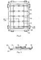
- FIG. 2 shows a possible embodiment of the frame 11 of the storage heater according to the invention.
- the frame 11 is welded together from profile bars in such a way that 20 rust-like connecting flat bars 21 are fastened vertically to a frame.
- fastening elements 22 for the side cover 14 in the form of short L-profile bars are arranged on the frame 20 in such a way that the air inlet openings 13 are formed with a large flow cross-section between the side cover 14 and the frame 20.
- the cladding 16 contains ceramic plates 24, for example tiles, which are combined in a holding frame 23 made of surface-treated metal.
- Protective grids 25 covering and protecting the air outlet openings 18 are arranged between the plates 24.
- Between the plates 24 and the holding frame 23 is along the same a refractory seal 29 is attached.
- a further thermal insulation 26 is arranged under the plates 24, which prevents excessive heating of the upper cladding 16 or an unwanted radiation of the stored energy. Under this thermal insulation 26 is the blind 19 for changing the flow cross-section of the air outlet openings 18.
- this blind 19 is a slide plate 27, which is arranged so as to be displaceable in grooves of the holding frame 23 designed for this purpose in a direction perpendicular to the longitudinal axis of the heater. Openings 28 are provided in the slide plate 27 in the same number as the number of air outlet openings 18 and, in the illustrated basic position of the slide plate 27, are offset with respect to the air outlet openings 18 in a direction perpendicular to the longitudinal axis of the storage heater.
- a control device 30 connected to a temperature controller and ensuring the automatic operating mode of the storage heater according to the invention is shown schematically in FIG.
- the control device 30 is connected via a control line 32 to a known and commercially available temperature controller 31 and contains an impulse-controlled lifting electromagnet 33, the movable part 35 acting in one direction against a compression spring 34 with an extension 37 of the slide plate forming the blind 19 27 is connected, the extension 37 is passed through an opening 36 in the holding frame 23.
- the control device 30 is detachably screwed to the holding frame 23 of the upper casing 16, preferably on the rear of the storage heater, via connecting means 38.
- a heat-insulating interruption section 39 is formed in the extension 37 of the slide plate 27.
- the outer cladding of the storage heater according to the invention can be designed freely.
- the side cladding 14 has a panel-like layer construction. A vertical section through such a structural unit can be seen from FIG.
- a further thermal insulation 40 is connected to the side cover 14 on the side of the side cover 14 that is adjacent to the riser space 15.
- this heat insulation 40 is made of refractory concrete with increased porosity, in which holding elements 41 for surface-treated screws 44 are installed.
- the screws 44 are used to fasten a further air and heat insulating layer 42 and a decorative plate 43.
- Two adjacent sides of each of these units are designed so that the units can be lined up in a horizontal and vertical direction via tongue and groove connections.
- the heating chamber 17 forms a practically closed airbag together with the riser chamber 15 and thus allows only a reduced heat emission on the upper cladding 16, which therefore only heats up to a lesser extent in accordance with the associated standard regulations.
- the same situation also exists in the area of the side cladding 14.
- the heat exchange body 7 which directly contacts the side cladding 14 could form a thermal bridge.
- the surface of the side panel 14, which is connected to the heat exchange body 7, is made of heat insulation material, which results in only a greatly reduced but uniform heating.
- the technical solution shown ensures that the storage heater, when closed, can only release a maximum of 20-30% of its stored energy content in the first eight hours following charging. This loss corresponds to the domestic and foreign standards.
- the warm air can leave the heater through the air outlet openings 18 in the upper casing 16; this allows the device to deliver approximately 45-60% of its stored energy in the first eight hours after charging.
- the intensity of the heat emission according to the higher value is of course higher; the uniform and desired heat emission is regulated by an automatic control device, which, deviating from the exemplary embodiment shown, can also be a bimetal element or a membrane box connected to the slide plate 27.
- the heat output is controlled in such a way that when the set lower temperature value is reached, a pulse is emitted from the temperature controller 31 via the control line 32 to the pulse-controlled electromagnet 33.
- the electromagnet 33 moves the slide plate 27 via the extension 37, i.e.
- the air outlet openings 18 have a flow cross-section of 1-25 cm 2 / kWh for correspondingly effective heat emission.
- a flap valve row is installed in the device instead of the slide plate 27.
- the control process is the same as that described above.
- the electrical switching and control of the heating elements 3 of the storage heater according to the invention takes place in a manner known per se, the explanation of which is not the task of this description.
- room temperatures can be maintained at any value by natural air convection and simple control without fan noise and without additional air draft.
Landscapes
- Engineering & Computer Science (AREA)
- Physics & Mathematics (AREA)
- Thermal Sciences (AREA)
- Chemical & Material Sciences (AREA)
- Combustion & Propulsion (AREA)
- Mechanical Engineering (AREA)
- General Engineering & Computer Science (AREA)
- Central Heating Systems (AREA)
- Supply Devices, Intensifiers, Converters, And Telemotors (AREA)
- Motor Or Generator Cooling System (AREA)
- Direct Air Heating By Heater Or Combustion Gas (AREA)
Applications Claiming Priority (2)
| Application Number | Priority Date | Filing Date | Title |
|---|---|---|---|
| HU84851A HU192542B (en) | 1984-03-02 | 1984-03-02 | Electric heating equipment of storage heater |
| HU85184 | 1984-03-02 |
Publications (2)
| Publication Number | Publication Date |
|---|---|
| EP0155339A2 true EP0155339A2 (fr) | 1985-09-25 |
| EP0155339A3 EP0155339A3 (fr) | 1987-05-06 |
Family
ID=10951695
Family Applications (1)
| Application Number | Title | Priority Date | Filing Date |
|---|---|---|---|
| EP84104283A Withdrawn EP0155339A3 (fr) | 1984-03-02 | 1984-04-16 | Radiateur à accumulation électrique |
Country Status (6)
| Country | Link |
|---|---|
| EP (1) | EP0155339A3 (fr) |
| DK (1) | DK344784A (fr) |
| FI (1) | FI850699L (fr) |
| GR (1) | GR80469B (fr) |
| HU (1) | HU192542B (fr) |
| NO (1) | NO850842L (fr) |
Cited By (2)
| Publication number | Priority date | Publication date | Assignee | Title |
|---|---|---|---|---|
| EP0324881A1 (fr) * | 1988-01-21 | 1989-07-26 | Abdul Aziz Abdullah Al-Saleh | Chauffe-eau domestique |
| CN108106009A (zh) * | 2017-11-06 | 2018-06-01 | 大同新成新材料股份有限公司 | 一种储热锅炉 |
Family Cites Families (7)
| Publication number | Priority date | Publication date | Assignee | Title |
|---|---|---|---|---|
| CH227762A (de) * | 1942-12-01 | 1943-07-15 | Kern Erwin | Elektrischer Speicherofen für Raumheizung. |
| FR897890A (fr) * | 1943-05-06 | 1945-04-04 | Perfectionnements apportés aux radiateurs électriques à accumulation de chaleur | |
| DE1579642A1 (de) * | 1951-01-28 | 1970-08-06 | Bauknecht Gmbh G | Waermespeicherofen |
| FR1237126A (fr) * | 1958-09-12 | 1960-07-29 | Perfectionnements apportés aux poêles à accumulation, notamment électriques | |
| DE1753193A1 (de) * | 1968-01-25 | 1971-07-15 | Schneider Christian | Elektrisches Speicherheizgeraet |
| JPS4833154B1 (fr) * | 1969-05-27 | 1973-10-12 | ||
| LU83100A1 (de) * | 1981-01-27 | 1982-09-10 | Arbed | Zum speichern thermischer energie geeignete speicherelemente und verfahren zu deren herstellung |
-
1984
- 1984-03-02 HU HU84851A patent/HU192542B/hu not_active IP Right Cessation
- 1984-04-16 EP EP84104283A patent/EP0155339A3/fr not_active Withdrawn
- 1984-07-13 DK DK344784A patent/DK344784A/da not_active Application Discontinuation
- 1984-09-25 GR GR80469A patent/GR80469B/el unknown
-
1985
- 1985-02-20 FI FI850699A patent/FI850699L/fi not_active Application Discontinuation
- 1985-03-01 NO NO850842A patent/NO850842L/no unknown
Cited By (2)
| Publication number | Priority date | Publication date | Assignee | Title |
|---|---|---|---|---|
| EP0324881A1 (fr) * | 1988-01-21 | 1989-07-26 | Abdul Aziz Abdullah Al-Saleh | Chauffe-eau domestique |
| CN108106009A (zh) * | 2017-11-06 | 2018-06-01 | 大同新成新材料股份有限公司 | 一种储热锅炉 |
Also Published As
| Publication number | Publication date |
|---|---|
| FI850699A0 (fi) | 1985-02-20 |
| NO850842L (no) | 1985-09-03 |
| HU192542B (en) | 1987-06-29 |
| DK344784D0 (da) | 1984-07-13 |
| DK344784A (da) | 1985-09-03 |
| FI850699A7 (fi) | 1985-09-03 |
| HUT37487A (en) | 1985-12-28 |
| FI850699L (fi) | 1985-09-03 |
| GR80469B (en) | 1985-01-28 |
| EP0155339A3 (fr) | 1987-05-06 |
Similar Documents
| Publication | Publication Date | Title |
|---|---|---|
| EP0705416B1 (fr) | Milieu thermique à changement d'état et radiateur comprenant un tel milieu | |
| DE2721209A1 (de) | Heizanlage und heizradiator | |
| DE2617701A1 (de) | Heizende tuer | |
| EP0670985A1 (fr) | Element mural comportant un chauffage integre. | |
| AT513992B1 (de) | Heizvorrichtung | |
| EP0155339A2 (fr) | Radiateur à accumulation électrique | |
| DE2731391A1 (de) | Vorrichtung zur nutzbarmachung der restwaerme eines abgases | |
| EP0097653A1 (fr) | Installation pour temperer un piece. | |
| DE2115235C2 (de) | Backofenbaugruppe mit erhitzten Wasserdampf und Kondensationswasser aufnehmenden und durch einen Herd beheizten ringförmig gekrümmten Röhren | |
| DE9401979U1 (de) | Heizkörper für Wohnräume o.dgl. | |
| DE3011434C2 (de) | Heizgerät für eine Warmwasser-Heizungsanlage | |
| DE2221765A1 (de) | Kachelofen, insbesondere kaminungebundener elektrisch beheizbarer kachelofen | |
| DD295904A5 (de) | Heizkessel | |
| DE1679324C (de) | Kachelofen Mehrraumluftheizung | |
| DE102010042877A1 (de) | Wärmespeicherherd | |
| DE1579777B2 (de) | Raumheizungsanlage mit waermespeicherofen | |
| CH651377A5 (de) | Heizkoerper mit einer rohrschlange. | |
| DE202014101251U1 (de) | Offener Kamin mit eingesetzter Kaminkassette | |
| DE620196C (de) | Elektrischer Ofen mit Waermespeicher fuer Raumbeheizung | |
| EP0171028A2 (fr) | Installation de chauffage | |
| CH626153A5 (en) | Heating aggregate for hot-water heating systems | |
| DE2610997B2 (de) | Elektrisches Wärmespeicher-Heizgerät | |
| DE19521414A1 (de) | Heizungssystem und Verfahren mit Sonnenkollektor | |
| EP0061665A1 (fr) | Chaudière-accumulateur de chaleur électrique encapsulé | |
| DE10020535A1 (de) | Klimatisierungsverfahren und Zuluftgerät zur Durchführung des Verfahrens |
Legal Events
| Date | Code | Title | Description |
|---|---|---|---|
| PUAI | Public reference made under article 153(3) epc to a published international application that has entered the european phase |
Free format text: ORIGINAL CODE: 0009012 |
|
| 17P | Request for examination filed |
Effective date: 19841217 |
|
| AK | Designated contracting states |
Designated state(s): AT BE CH DE FR GB IT LI LU NL SE |
|
| PUAL | Search report despatched |
Free format text: ORIGINAL CODE: 0009013 |
|
| AK | Designated contracting states |
Kind code of ref document: A3 Designated state(s): AT BE CH DE FR GB IT LI LU NL SE |
|
| STAA | Information on the status of an ep patent application or granted ep patent |
Free format text: STATUS: THE APPLICATION HAS BEEN WITHDRAWN |
|
| 18W | Application withdrawn |
Withdrawal date: 19870513 |
|
| RIN1 | Information on inventor provided before grant (corrected) |
Inventor name: PERENYI, PETER Inventor name: KRECHOVA, KATALIN Inventor name: SZABO, ZOLTAN |