EP0155350B1 - Spendebehälter mit einem druckausgleichenden Ventil - Google Patents
Spendebehälter mit einem druckausgleichenden Ventil Download PDFInfo
- Publication number
- EP0155350B1 EP0155350B1 EP84110233A EP84110233A EP0155350B1 EP 0155350 B1 EP0155350 B1 EP 0155350B1 EP 84110233 A EP84110233 A EP 84110233A EP 84110233 A EP84110233 A EP 84110233A EP 0155350 B1 EP0155350 B1 EP 0155350B1
- Authority
- EP
- European Patent Office
- Prior art keywords
- liquid
- applicator
- container
- opening
- head
- Prior art date
- Legal status (The legal status is an assumption and is not a legal conclusion. Google has not performed a legal analysis and makes no representation as to the accuracy of the status listed.)
- Expired
Links
Images
Classifications
-
- A—HUMAN NECESSITIES
- A45—HAND OR TRAVELLING ARTICLES
- A45D—HAIRDRESSING OR SHAVING EQUIPMENT; EQUIPMENT FOR COSMETICS OR COSMETIC TREATMENTS, e.g. FOR MANICURING OR PEDICURING
- A45D34/00—Containers or accessories specially adapted for handling liquid toiletry or cosmetic substances, e.g. perfumes
- A45D34/04—Appliances specially adapted for applying liquid, e.g. using roller or ball
-
- B—PERFORMING OPERATIONS; TRANSPORTING
- B65—CONVEYING; PACKING; STORING; HANDLING THIN OR FILAMENTARY MATERIAL
- B65D—CONTAINERS FOR STORAGE OR TRANSPORT OF ARTICLES OR MATERIALS, e.g. BAGS, BARRELS, BOTTLES, BOXES, CANS, CARTONS, CRATES, DRUMS, JARS, TANKS, HOPPERS, FORWARDING CONTAINERS; ACCESSORIES, CLOSURES, OR FITTINGS THEREFOR; PACKAGING ELEMENTS; PACKAGES
- B65D47/00—Closures with filling and discharging, or with discharging, devices
- B65D47/42—Closures with filling and discharging, or with discharging, devices with pads or like contents-applying means
-
- A—HUMAN NECESSITIES
- A45—HAND OR TRAVELLING ARTICLES
- A45D—HAIRDRESSING OR SHAVING EQUIPMENT; EQUIPMENT FOR COSMETICS OR COSMETIC TREATMENTS, e.g. FOR MANICURING OR PEDICURING
- A45D2200/00—Details not otherwise provided for in A45D
- A45D2200/10—Details of applicators
- A45D2200/1009—Applicators comprising a pad, tissue, sponge, or the like
- A45D2200/1018—Applicators comprising a pad, tissue, sponge, or the like comprising a pad, i.e. a cushion-like mass of soft material, with or without gripping means
Definitions
- the present invention relates to a liquid applicator for dispensing toiletries to the skin, and particularly for the application of antiperspirants and deodorants to the human axilla.
- Liquid applicators in general are well-known in the prior art, particularly the roll-on type commonly used for antiperspirants and deodorants. These are disclosed, for example, in U.S. Patents 2,749,566; 2,923,957 and 2,998,616. Because of problems with roll-on type applicators, Berghahn, et al., U.S. Patents 4,050,826 and 4,111,567 devised a liquid applicator comprising a container fitted with a head having a fixed, shaped form made of a non-flexible, non-deformable, sintered porous synthetic plastics resin having a controlled porosity and having omni-directional, inter- connecting pores.
- liquid overflow problems associated with conventional roll-ons are also present in this type of head and are solved by the provisions of a liquid collecting channel adjacent the shaped applicator, permitting the excess liquid to drain back via the channel into an opening through the head into the liquid reservoir. This avoids an accumulation of liquid on the surface of the applicator and resulting crystallization of product being delivered.
- the porous plastic applicator of Berghahn etal. resembles the conventional roll-on applicator except that it is stationary and has a drain channel.
- the liquid product being delivered must be brought into contact with the applicator head in order for the liquid to be delivered to the surface by capillary action. This requires inverting the container, as is true of the roll-on type of head, since there will always be dead space between the liquid in the reservoir and the applicator head. Thus, no way is provided for the liquid in the reservoir always to be in contact with the applicator head.
- a delivery system for liquid toiletry products whereby a liquid product is absorbed onto an absorbent material which is in intimate contact with a non-flexible, non-deformable, sintered, porous synthetic resin applicator head having a controlled porosity and omni-directional inter-connecting pores, and whereby the absorbed liquid product is continuously delivered to the porous applicator head by capillary flow on demand.
- the device has the advantage of eliminating dead air space and the need to invert the container, since the liquid is always in contact with the applicator head and available on demand at the surface of the applicator head.
- GB-A-2084455 discloses a device of the above-mentioned type of liquid applicator having means to create pressure on the liquid.
- the present invention basically comprises means to generate pressure within the container and wherein the porous plastic dispensing head has a specially designed and constructed capillary pressure compensating valve.
- the applicator head may be of any suitable configuration, but a convex outer surface has been found to be particularly suitable for contact with various parts of the human body.
- the applicator head may have a hemispherical outer surface.
- the materials which are used to make the shaped applicator head are non-flexible, non-deformable, sintered, porous synthetic resins having a controlled porosity and having omni-directional interconnecting pores, formed of aggregates of united polymer particles.
- the degree of porosity of the porous materials can be controlled in their manufacture, thus insuring a wide range of porosity to suit a wide range of liquid products of varying viscosities.
- Sintered, porous applicator heads may be fabricated of high-density polyethylene, low-density polyethylene, ultra-high molecular weight polyethylene, poly-propylene, polyvinylidene fluoride, and the like.
- the pore size of the applicator may vary widely, depending on the liquid to be delivered. Low-viscosity liquids, such as perfumes, may best be delivered via a small- pore plastic applicator, e.g., one micron or less. In general, the pore size may vary between about one to 200 pm, and for most purposes, generally about 10-50 um are preferred.
- the capillary pressure compensating valve is preferably formed at or near the center area of the dispenser head.
- the capillary valve must be of such a diameter that it holds liquid by capillary force even when the container is upside down. It further should maintain its integrity and size. In addition, it should be constructed such that it is free from debris and remains so.
- One method of meeting these requirements is by drilling a small precision capillary hole through the head with a countersink area which prevents accumulation of debris, and clogging of the hole opening which can occur due to the small diameter of the hole. This forms a capillary pressure compensating valve.
- the diameter of the capillary valve should range from about 0.127 to 0.762 mm (0.005 to 0.030 inches), preferably 0.254 to 0.635 mm (.010 to 0.025 inches).
- the size of the capillary pressure compensating valve is in relationship to the surface tension of the product and the desired pressure differential required to maintain the valve functionality.
- the porous applicator head is attached to an annular plastic diaphragm spring which in turn fits into the top opening of the container which forms a reservoir for the liquid material to be dispensed.
- the container can be filled solely with the liquid product.
- the reservoir may contain an absorbent material, onto which the liquid to be delivered is absorbed, and this absorbent material is in direct and intimate contact with the porous applicator head. This aspect of the invention insures continuous contact of the liquid with the applicator head and facilitates delivery of the liquid on demand by capillary flow.
- the container may obviously be of any suitable material, such as metal, glass, or plastic.
- the delivery system of the invention may be used to deliver any topical liquid product to the skin. These may include, for example, after-shave lotions, pre-shave lotions, skin lubricants or emollients, suntan lotions, fragrances (perfumes, colognes, etc.), topical therapeutics (analgesics, acne formulations, antiseptics, etc.), lip and face rouge and the like.
- the delivery system is particularly useful in applying antiperspirants and deodorants and avoids the problems associated with roll-on applicators.
- the invention provides a means of applying a low viscosity, fast drying, non-sticky solution of aluminum chlorhydrate, avoiding the undesirable features of roll-ons, pump sprays, and sticks.
- porous plastic materials are hydrophobic and do not "wet" with water, it may be necessary to add alcohol to antiperspirant formula to transfer the product from the container to the applicator head. Crystallization of the solid components of the solution, such as aluminum chlorhydrate, may be avoided by the addition of certain esters, such as isopropyl myristate or isopropyl palmitate.
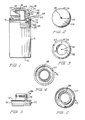
- Figures 4, 5 and 6 are respectively a top plan view, an elevational view in cross-section, and a bottom plan view of the annular plastic spring.
- the liquid delivery system comprises an outer case 10 having a base 12. Case 10 is shown with threads 16 to attach a cap, not shown, which could alternatively be attached by a friction fit. Case 10 contains the liquid product 34 to be dispensed.
- a porous plastic applicator head 20 is fitted onto an annular elastic spring 35. Spring 35 has two concentric cylindrical segments, cylindrical segment 36 with a flange 37 on the top and an inner cylindrical segment 38. The outer cylindrical segment 36 and inner cylindrical segment 38 are joined by an annular undulate member 40, having a downward undulation.
- Applicator head 20 has an inner cylindrical wall 31 which fits over inner cylinder 38 of spring 35 in fluid tight relationship.
- inner cylinder 38 has annular ridges 42 which engage inner wall 31 of applicator head 20 and fasten the head firmly.
- the upper end 41 of inner cylinder 38 may be tapered inwardly to facilitate insertion into head 20.
- the upper end 41 of the inner cylinder 38 in addition to fastening head 20 to diaphragm spring 35, also acts as an impervious sleeve to seal the inner wall 31 of applicator head 20 so that liquid product is directed toward the upper surface 43 of head 20.
- the applicator head-spring assembly is inserted into container 10 and the outer segment 36 of spring 35 forms a fluid tight friction fit with flange 37 resting on the top rim 44 of container 10.
- Applicator head 20 is cut in at the lower end so that it extends within outer cylindrical segment 36 of spring 35. In this arrangement the head 20 can move into the container 10 when pressure is applied to the head and the undulate surface 40 of spring 35 is deformed. Applicator head 20 may be depressed until the shoulder 22 of head 20 contacts flange 37 of spring 35 which then acts as a stop.
- Applicator head 20 has a capillary pressure compensation valve 45 having a counter-sink 46 at its upper end.
- Capillary valve 45 contains liquid, except when a differential pressure forces the liquid out. Afterward the pressure differential within and without the container stabilizes but never goes to zero.
- container 10 is first inverted wetting the inner surface 28, and then by capillary action liquid 34 flows to the pores of head 20.
- the outer surface 24 of head 20 is rubbed against the skin, liquid 34 is applied to the skin.
- the pressure on head 20 pushes the head into container 10 increasing the pressure in the container, forcing liquid 34 out through the pores of head 20, thus supplementing the capillary flow and assuring an adequate flow of liquid product 34 to the outer surface of head 20.
- applicator head 20 has a somewhat flattened outer surface 24 with the vertical side section 47 being thicker than the upper surfaces 24. This serves two purposes. First, it will serve to absorb any liquid overflow, thus minimizing any liquid dripping down the sides of head 20 and container 10. Second, the flattened head provides a larger spreading area for spreading the liquid 34 over a surface. Any liquid that runs down the sides will be reabsorbed by the thickened area 47 of head 20. The removal of liquid from applicator head 20 builds up a vacuum pressure in container 10. When pressure on head 20 is released, and head 20 rises, the outside pressure forces the liquid from capillary valve 45, air enters container 10 and the pressure inside and outside container 10 are essentially equalized. This valve action takes place each time head 20 is depressed and released. Thus no vacuum can build up within container 10 to impede the flow of liquid through the pores of head 20.
- capillary valve 45 is a true valve, and not a vent hole. Capillary valve 45 opens and closes in response to differential pressure inside and outside the container. As described above, valve 45 prevents vacuum build up within container 10. After the liquid has been forced from valve 45 to open the valve and pressure compensation occurs, liquid fills the valve either (a) through the pores of head 20 via capillary flow, or (b) via capillary flow from the inner or outer surface of the dome into the valve opening. This sequence occurs each time the applicator head 20 is depressed and released. A conventional vent hole open to the atmosphere is not desirable since it leaks liquid when the package is inverted and also squirting of excess liquid when the applicator head is depressed.
- Capillary valve 45 also serves to relieve excess pressure build up within container 10. This can occur when the container should be subjected to higher temperature, higher altitude, or changing barometric pressure. In this case, the increased pressure within container 10 forces liquid from valve 45 and air escapes from inside container 10 to essentially equalize inner and outer pressure. If this did not take place, the liquid in the pores of head 20 would be forced out and run down the sides of the container.
- case 10 may be filled with an absorbent material not shown filling container 10, and in contact with inner surface 28 of applicator head 20.
- the inner cylinder 38 may be a separate piece fitting within a separate diaphragm spring.
- the applicator head with a capillary pressure compensating valve was made as follows:
- a porous plastic applicator head of polyethylene, having average pore size of 16 pm or .000016 inches was used.
- a heated cone shaped mandrel was utilized to produce a counter-sink area with a smooth melted surface in the upper surface of the applicator head.
- the porous heads were then cooled to minus 40°C for about 1/2 hour, or sufficient time to cool both plastic and occluded air.
- a (0.018") drill with a counter-sink was used to drill through the upper surface at the center of the heat treated area. The drilled thickness was about (3/8 inches). In order not to exceed the viscoelastic point, drilling was done slowly so as not to generate heat. Rotational speed was 150 revolutions per minute and speed of penetration was five seconds per 2.54 cm (1 inch). At this rate, there was no melting or torn stringy fibers of plastic within the drilled cavity.
- a container was assembled using the obtained applicator head.
- the container was filled with the following formulation:
- An identical package without use of internal pressure or capillary valve delivered a very low amount of liquid and soon built up a vacuum within the container so that liquid delivery was even further reduced.
- Pre-shave (beard softener and lubricant)
Landscapes
- Engineering & Computer Science (AREA)
- Mechanical Engineering (AREA)
- Closures For Containers (AREA)
- Containers And Packaging Bodies Having A Special Means To Remove Contents (AREA)
- Coating Apparatus (AREA)
- Organic Low-Molecular-Weight Compounds And Preparation Thereof (AREA)
Claims (10)
Applications Claiming Priority (2)
| Application Number | Priority Date | Filing Date | Title |
|---|---|---|---|
| US52906883A | 1983-09-02 | 1983-09-02 | |
| US529068 | 1983-09-02 |
Publications (3)
| Publication Number | Publication Date |
|---|---|
| EP0155350A2 EP0155350A2 (de) | 1985-09-25 |
| EP0155350A3 EP0155350A3 (en) | 1986-09-17 |
| EP0155350B1 true EP0155350B1 (de) | 1988-12-28 |
Family
ID=24108388
Family Applications (1)
| Application Number | Title | Priority Date | Filing Date |
|---|---|---|---|
| EP84110233A Expired EP0155350B1 (de) | 1983-09-02 | 1984-08-28 | Spendebehälter mit einem druckausgleichenden Ventil |
Country Status (14)
| Country | Link |
|---|---|
| US (1) | US5073057A (de) |
| EP (1) | EP0155350B1 (de) |
| JP (1) | JPS6090153A (de) |
| KR (1) | KR920000304B1 (de) |
| AR (1) | AR244633A1 (de) |
| AU (1) | AU570497B2 (de) |
| BR (1) | BR8404358A (de) |
| CA (1) | CA1233785A (de) |
| DE (1) | DE3475746D1 (de) |
| DK (1) | DK163794C (de) |
| MX (1) | MX160988A (de) |
| NO (1) | NO843482L (de) |
| NZ (1) | NZ209369A (de) |
| ZA (1) | ZA846857B (de) |
Cited By (1)
| Publication number | Priority date | Publication date | Assignee | Title |
|---|---|---|---|---|
| US7125189B2 (en) | 2001-11-19 | 2006-10-24 | L'oreal S.A. | Device, system, and method for applying a product |
Families Citing this family (38)
| Publication number | Priority date | Publication date | Assignee | Title |
|---|---|---|---|---|
| GB2240032A (en) * | 1990-01-19 | 1991-07-24 | Unilever Plc | Applicator for liquids |
| US5676481A (en) * | 1991-09-26 | 1997-10-14 | Gillette Company | Marking instruments |
| FR2713060B1 (fr) * | 1993-11-29 | 1996-02-02 | Oreal | Dispositif applicateur pour liquide. |
| JPH09510119A (ja) * | 1994-03-09 | 1997-10-14 | ザ、プロクター、エンド、ギャンブル、カンパニー | 製品を小出ししない大きな付着/分配面を持つ製品ディスペンサ |
| FR2731681B1 (fr) * | 1995-03-17 | 1997-04-30 | Oreal | Applicateur de produit de consistance visqueuse, comportant un organe de distribution poreux |
| US6196747B1 (en) | 1995-12-21 | 2001-03-06 | Creative Packaging Corp. | Product dispensing cover |
| US5660589A (en) * | 1995-12-26 | 1997-08-26 | Dana Corporation | Lubricant retaining valve for universal joint |
| FR2744104B1 (fr) * | 1996-01-29 | 1998-03-20 | Oreal | Dispositif de conditionnement, de distribution et d'application d'un gel ou mousse |
| US6231259B1 (en) | 1996-07-26 | 2001-05-15 | The Gillette Company | Viscous product dispenser with porous dome |
| US5833382A (en) * | 1996-08-19 | 1998-11-10 | Helene Curtis, Inc. | Push-up dispenser suitable for dilatant materials |
| JPH10512529A (ja) * | 1996-09-17 | 1998-12-02 | ザ、プロクター、エンド、ギャンブル、カンパニー | パッケージ及び流体製品の組み合わせ |
| US5851079A (en) * | 1996-10-25 | 1998-12-22 | The Procter & Gamble Company | Simplified undirectional twist-up dispensing device with incremental dosing |
| US6036391A (en) * | 1997-12-19 | 2000-03-14 | Prestone Products Corporation | Hand-held applicator for applying a cleaning or polishing solution to a surface |
| USD416112S (en) | 1998-03-06 | 1999-11-02 | Prestone Products Corporation | Hand-held applicator for applying a cleaning or polishing solution to a surface |
| USD416356S (en) | 1998-09-28 | 1999-11-09 | The Procter & Gamble Company | Container |
| DE19853253A1 (de) * | 1998-11-18 | 2000-05-25 | Beiersdorf Ag | Vorrichtung zum Auftragen flüssiger Medien auf die Haut |
| US6030138A (en) | 1998-11-23 | 2000-02-29 | Colgate-Palmolive Company | Microporous applicator |
| DE19920624A1 (de) | 1999-05-05 | 2000-11-09 | Beiersdorf Ag | Vorrichtung zum Auftragen viskoser Medien |
| US6637966B2 (en) | 2001-04-06 | 2003-10-28 | Keith Roberts | Sealable toiletry article |
| US7117818B2 (en) * | 2002-06-24 | 2006-10-10 | Medialore, Llc | Multipurpose flow control device |
| EP1585402A1 (de) * | 2003-01-14 | 2005-10-19 | Unilever Plc | Applikator für flüssige kosmetika |
| US20050135867A1 (en) * | 2003-10-13 | 2005-06-23 | Gueret Jean-Louis H. | Substance packaging and applicator device |
| US7144174B2 (en) * | 2004-12-30 | 2006-12-05 | Unilever Home & Personal Care Usa Division Of Conopco, Inc. | Applicator for liquid cosmetic compositions |
| AR056792A1 (es) * | 2005-11-12 | 2007-10-24 | Unilever Nv | Dispensador capilar |
| US7874756B2 (en) | 2006-06-07 | 2011-01-25 | Beiersdorf Ag | Kit for the application of a fluid preparation |
| USD562699S1 (en) | 2006-06-19 | 2008-02-26 | Green Dennis E | Liquid perfume compact |
| USD554529S1 (en) | 2006-12-26 | 2007-11-06 | Green Dennis E | Perfume applicator |
| RU2010101672A (ru) * | 2007-06-20 | 2011-07-27 | Мек Дайнэмикс Корпорэйшн (Us) | Способы и устройство для измерения свертываемости крови |
| US20090173283A1 (en) * | 2008-01-07 | 2009-07-09 | Medialore, Llc | Flow Control Device |
| KR200451704Y1 (ko) | 2008-07-23 | 2011-01-06 | 주식회사 생 코레 인터내셔날 | 액상화장품용 퍼프와 퍼프지지대의 액상화장품 배출구조 |
| WO2010098512A1 (ko) * | 2009-02-26 | 2010-09-02 | Roh Byung-Hoo | 밸브개폐구조를 갖는 액상화장용 퍼프 |
| KR101102601B1 (ko) | 2009-02-26 | 2012-01-04 | (주)제스폰 | 밸브 개폐구조를 갖는 액상 화장용 퍼프 |
| JP5826504B2 (ja) * | 2011-03-18 | 2015-12-02 | 小池化学株式会社 | 塗布用エアゾール製品 |
| USD708402S1 (en) * | 2012-06-27 | 2014-07-01 | Ctb, Inc. | Breather cap for use in connection with a watering assembly |
| WO2018150307A1 (en) | 2017-02-14 | 2018-08-23 | 3M Innovative Properties Company | Bandage composition dispenser |
| US10702040B2 (en) * | 2017-11-16 | 2020-07-07 | RLM Group Ltd. | Liquid dermatological agent dispensing device |
| US11364183B2 (en) | 2018-04-30 | 2022-06-21 | L'oréal | Cosmetic system containing an applicator and a gel composition |
| ES1300672Y (es) | 2023-04-27 | 2023-09-08 | Quadpack Ind S A | Envase dispensador de productos cosméticos o farmacéuticos |
Family Cites Families (17)
| Publication number | Priority date | Publication date | Assignee | Title |
|---|---|---|---|---|
| US1949162A (en) * | 1934-02-27 | kallenbach | ||
| US2923957A (en) * | 1960-02-09 | gentile | ||
| US1621567A (en) * | 1925-12-17 | 1927-03-22 | Gold Dust Corp | Applicator cap |
| US2749566A (en) * | 1952-09-04 | 1956-06-12 | Bristol Myers Co | Dispenser |
| US2921324A (en) * | 1956-02-03 | 1960-01-19 | Colgate Palmolive Co | Scouring device |
| US2998616A (en) * | 1957-10-21 | 1961-09-05 | Bristol Myers Co | Ball applicator dispensers |
| US2975465A (en) * | 1958-09-25 | 1961-03-21 | Gillette Co | Liquid dispensing applicator |
| US2996750A (en) * | 1959-04-06 | 1961-08-22 | Cholet Bertram | Fountain pen |
| GB997630A (en) * | 1963-10-16 | 1965-07-07 | Jerclaydon Inc | Improvements in dispensing applicators |
| US3340561A (en) * | 1965-02-18 | 1967-09-12 | Schwartzman Gilbert | Applicator having one-piece body |
| US3610766A (en) * | 1968-07-13 | 1971-10-05 | Montblanc Simplo Gmbh | Fountain pen |
| JPS4921233U (de) * | 1972-05-25 | 1974-02-22 | ||
| JPS5755114Y2 (de) * | 1975-09-22 | 1982-11-29 | ||
| US4050826A (en) * | 1976-02-11 | 1977-09-27 | Bristol-Myers Company | Liquid applicator |
| FI812691A7 (fi) * | 1980-09-02 | 1982-03-03 | American Cyanamid Co | Uusi nestemäinen hygienanhoitoaineiden levitysjärjestelmä. |
| US4384589A (en) * | 1981-07-27 | 1983-05-24 | American Cyanamid Company | Novel liquid delivery system for toiletries |
| US4480940A (en) * | 1982-04-14 | 1984-11-06 | American Cyanamid Company | Flexible diaphragm for dispensing product |
-
1984
- 1984-08-28 EP EP84110233A patent/EP0155350B1/de not_active Expired
- 1984-08-28 DE DE8484110233T patent/DE3475746D1/de not_active Expired
- 1984-08-29 NZ NZ209369A patent/NZ209369A/en unknown
- 1984-08-30 AU AU32534/84A patent/AU570497B2/en not_active Ceased
- 1984-08-31 CA CA000462215A patent/CA1233785A/en not_active Expired
- 1984-08-31 ZA ZA846857A patent/ZA846857B/xx unknown
- 1984-08-31 NO NO843482A patent/NO843482L/no unknown
- 1984-08-31 AR AR84297808A patent/AR244633A1/es active
- 1984-08-31 JP JP59180879A patent/JPS6090153A/ja active Pending
- 1984-08-31 BR BR8404358A patent/BR8404358A/pt not_active IP Right Cessation
- 1984-08-31 MX MX202591A patent/MX160988A/es unknown
- 1984-08-31 DK DK419684A patent/DK163794C/da not_active IP Right Cessation
- 1984-09-01 KR KR1019840005385A patent/KR920000304B1/ko not_active Expired
-
1990
- 1990-09-21 US US07/590,449 patent/US5073057A/en not_active Expired - Fee Related
Cited By (1)
| Publication number | Priority date | Publication date | Assignee | Title |
|---|---|---|---|---|
| US7125189B2 (en) | 2001-11-19 | 2006-10-24 | L'oreal S.A. | Device, system, and method for applying a product |
Also Published As
| Publication number | Publication date |
|---|---|
| AU570497B2 (en) | 1988-03-17 |
| AR244633A1 (es) | 1993-11-30 |
| DK419684D0 (da) | 1984-08-31 |
| EP0155350A3 (en) | 1986-09-17 |
| DK163794C (da) | 1992-09-07 |
| NO843482L (no) | 1985-03-04 |
| DE3475746D1 (en) | 1989-02-02 |
| KR850002406A (ko) | 1985-05-13 |
| EP0155350A2 (de) | 1985-09-25 |
| JPS6090153A (ja) | 1985-05-21 |
| ZA846857B (en) | 1985-04-24 |
| AU3253484A (en) | 1985-03-07 |
| KR920000304B1 (ko) | 1992-01-11 |
| MX160988A (es) | 1990-06-29 |
| NZ209369A (en) | 1988-01-08 |
| CA1233785A (en) | 1988-03-08 |
| BR8404358A (pt) | 1985-07-30 |
| DK163794B (da) | 1992-04-06 |
| DK419684A (da) | 1985-03-03 |
| US5073057A (en) | 1991-12-17 |
Similar Documents
| Publication | Publication Date | Title |
|---|---|---|
| EP0155350A2 (de) | Spendebehälter mit einem druckausgleichenden Ventil | |
| US4480940A (en) | Flexible diaphragm for dispensing product | |
| US4384589A (en) | Novel liquid delivery system for toiletries | |
| US4050826A (en) | Liquid applicator | |
| EP0167657B1 (de) | Aufsaugende Hülse eines Spendersystems für Toilettenprodukte | |
| US9215921B2 (en) | Packaging and applicator device including an applicator member | |
| US5567073A (en) | Applicator device for liquid | |
| CA1162164A (en) | Liquid delivery system for toiletries | |
| US5116156A (en) | Roller-type material applicator | |
| EP3710097B1 (de) | Abgabevorrichtung für flüssiges dermatologisches mittel | |
| US2853727A (en) | Dispenser for liquids | |
| WO2002008082A1 (en) | Liquid applicator | |
| US4030844A (en) | Roll-on dispenser bottle assembly | |
| US8192100B2 (en) | Fluid applicator device and method of using same | |
| EP0155349B1 (de) | Spendebehälter | |
| CA1103213A (en) | Roll-on dispenser with a flexible variable porosity membrane | |
| EP0141126A1 (de) | Flüssigkeitsspendersystem für Toilettenprodukte | |
| US2858558A (en) | Combination bottle closure and ball applicator | |
| GB2083743A (en) | Liquid delivery system for toiletries and the like | |
| GB1571662A (en) | Liquid applicator | |
| US3355241A (en) | Applicator package | |
| CA1318279C (en) | Solid stick product applicator having an open-celled attachment pad | |
| HK40027125A (en) | Liquid dermatological agent dispensing device |
Legal Events
| Date | Code | Title | Description |
|---|---|---|---|
| PUAI | Public reference made under article 153(3) epc to a published international application that has entered the european phase |
Free format text: ORIGINAL CODE: 0009012 |
|
| AK | Designated contracting states |
Designated state(s): BE DE FR GB IT LU NL SE |
|
| PUAL | Search report despatched |
Free format text: ORIGINAL CODE: 0009013 |
|
| AK | Designated contracting states |
Kind code of ref document: A3 Designated state(s): BE DE FR GB IT LU NL SE |
|
| 17P | Request for examination filed |
Effective date: 19870213 |
|
| 17Q | First examination report despatched |
Effective date: 19870616 |
|
| GRAA | (expected) grant |
Free format text: ORIGINAL CODE: 0009210 |
|
| AK | Designated contracting states |
Kind code of ref document: B1 Designated state(s): BE DE FR GB IT LU NL SE |
|
| REF | Corresponds to: |
Ref document number: 3475746 Country of ref document: DE Date of ref document: 19890202 |
|
| ET | Fr: translation filed | ||
| ITF | It: translation for a ep patent filed | ||
| PLBE | No opposition filed within time limit |
Free format text: ORIGINAL CODE: 0009261 |
|
| STAA | Information on the status of an ep patent application or granted ep patent |
Free format text: STATUS: NO OPPOSITION FILED WITHIN TIME LIMIT |
|
| 26N | No opposition filed | ||
| NLS | Nl: assignments of ep-patents |
Owner name: THE PROCTER & GAMBLE COMPANY TE CINCINNATI, OHIO, |
|
| ITTA | It: last paid annual fee | ||
| REG | Reference to a national code |
Ref country code: FR Ref legal event code: TP |
|
| PGFP | Annual fee paid to national office [announced via postgrant information from national office to epo] |
Ref country code: SE Payment date: 19930806 Year of fee payment: 10 |
|
| PGFP | Annual fee paid to national office [announced via postgrant information from national office to epo] |
Ref country code: NL Payment date: 19930831 Year of fee payment: 10 |
|
| PGFP | Annual fee paid to national office [announced via postgrant information from national office to epo] |
Ref country code: BE Payment date: 19930909 Year of fee payment: 10 |
|
| PGFP | Annual fee paid to national office [announced via postgrant information from national office to epo] |
Ref country code: LU Payment date: 19930928 Year of fee payment: 10 |
|
| EPTA | Lu: last paid annual fee | ||
| PG25 | Lapsed in a contracting state [announced via postgrant information from national office to epo] |
Ref country code: LU Free format text: LAPSE BECAUSE OF NON-PAYMENT OF DUE FEES Effective date: 19940828 |
|
| PG25 | Lapsed in a contracting state [announced via postgrant information from national office to epo] |
Ref country code: SE Effective date: 19940829 |
|
| PG25 | Lapsed in a contracting state [announced via postgrant information from national office to epo] |
Ref country code: BE Effective date: 19940831 |
|
| EAL | Se: european patent in force in sweden |
Ref document number: 84110233.8 |
|
| BERE | Be: lapsed |
Owner name: THE PROCTER & GAMBLE CY Effective date: 19940831 |
|
| PG25 | Lapsed in a contracting state [announced via postgrant information from national office to epo] |
Ref country code: NL Effective date: 19950301 |
|
| NLV4 | Nl: lapsed or anulled due to non-payment of the annual fee | ||
| EUG | Se: european patent has lapsed |
Ref document number: 84110233.8 |
|
| PGFP | Annual fee paid to national office [announced via postgrant information from national office to epo] |
Ref country code: FR Payment date: 19960809 Year of fee payment: 13 |
|
| PG25 | Lapsed in a contracting state [announced via postgrant information from national office to epo] |
Ref country code: FR Free format text: LAPSE BECAUSE OF NON-PAYMENT OF DUE FEES Effective date: 19980430 |
|
| REG | Reference to a national code |
Ref country code: FR Ref legal event code: ST |
|
| REG | Reference to a national code |
Ref country code: GB Ref legal event code: IF02 |
|
| PGFP | Annual fee paid to national office [announced via postgrant information from national office to epo] |
Ref country code: GB Payment date: 20030702 Year of fee payment: 20 |
|
| PGFP | Annual fee paid to national office [announced via postgrant information from national office to epo] |
Ref country code: DE Payment date: 20030829 Year of fee payment: 20 |
|
| PG25 | Lapsed in a contracting state [announced via postgrant information from national office to epo] |
Ref country code: GB Free format text: LAPSE BECAUSE OF EXPIRATION OF PROTECTION Effective date: 20040827 |
|
| REG | Reference to a national code |
Ref country code: GB Ref legal event code: PE20 |