EP0155377A1 - Agencement de dynodes pour multiplicateur d'électrons - Google Patents
Agencement de dynodes pour multiplicateur d'électrons Download PDFInfo
- Publication number
- EP0155377A1 EP0155377A1 EP84115140A EP84115140A EP0155377A1 EP 0155377 A1 EP0155377 A1 EP 0155377A1 EP 84115140 A EP84115140 A EP 84115140A EP 84115140 A EP84115140 A EP 84115140A EP 0155377 A1 EP0155377 A1 EP 0155377A1
- Authority
- EP
- European Patent Office
- Prior art keywords
- dynodes
- grid
- voltage input
- control
- voltage
- Prior art date
- Legal status (The legal status is an assumption and is not a legal conclusion. Google has not performed a legal analysis and makes no representation as to the accuracy of the status listed.)
- Withdrawn
Links
Images

Classifications
-
- H—ELECTRICITY
- H01—ELECTRIC ELEMENTS
- H01J—ELECTRIC DISCHARGE TUBES OR DISCHARGE LAMPS
- H01J43/00—Secondary-emission tubes; Electron-multiplier tubes
- H01J43/04—Electron multipliers
- H01J43/30—Circuit arrangements not adapted to a particular application of the tube and not otherwise provided for
-
- H—ELECTRICITY
- H01—ELECTRIC ELEMENTS
- H01J—ELECTRIC DISCHARGE TUBES OR DISCHARGE LAMPS
- H01J43/00—Secondary-emission tubes; Electron-multiplier tubes
- H01J43/04—Electron multipliers
- H01J43/06—Electrode arrangements
Definitions
- the present invention relates to a dynodes arrangement for an electron multiplier.
- the invention is utilized in scintillation gamma cameras for nuclear diagnosis purposes.
- the British Patent Application 2,067,281 describes a method and circuitry for retuning by means of an automatic gain control (AGC) amplifier.
- AGC automatic gain control
- the British Patent 977,827 illustrates a method and circuitry for retuning by modifying the potential of the anode and some of the dynodes, when the total gain of the photomultiplier exceeds a predetermined value, by directly connecting together the anode and a number of dynodes which are closest to the anode.
- the copending application Serial No. 343,207 filed January 27, 1982, by Dennis E. Persyk, entitled "Radiation Detector Assembly for Generating a Two-Dimensional Image” shows a radiation detector having a photocathode, an electron multiplier such as a multichannel plate, and a grid positioned between the photocathode and the electron multiplier.
- a first electrical field is provided between the photocathode and the grid and a second electrical field is provided between the grid and the electron multiplier; whereby the strength of the second electrical field is larger than the strength of the first electrical field. Due to this the impingement area of a packet of photo electrons on the electron multipier input is enlarged and thus, simultaneously, the electron density is reduced, which in certain applications is a favorable result.
- a dynodes arrangement for an electron multiplier which comprises:
- the control grid allows for tuning of the gain of a photomultiplier tube in a technically simple manner, whereby all aforementioned limitations of the prior art do not any longer influence the tuning process.
- a scintillation gamma camera which comprises:
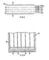
- a photonultiplier tube 10 comprises a housing 12 having an optical input window 14. Behind the input window 14 is positioned a photocathode 16 with the high voltage HV.
- the anode is generally designated-by 18.
- dynodes DY1 to DYn and the screen grids Gl and G3 between dynodes DY i and DY i+1 are connected by means of an ohmic resistances voltage divider Rl to Rn with a voltage supply source V.
- the control grid G2 is also connected with the voltage supply source V by means of variable ohmic resistance (potentiometer) R v .
- the dynodes are so-called venetian-blind dynodes comprising each a transparent grid 22 across its top (electron-impinging surface) as is customary to reduce electric field penetration from the preceding dynode.
- venetian-blind dynodes comprising each a transparent grid 22 across its top (electron-impinging surface) as is customary to reduce electric field penetration from the preceding dynode.
- other dynode types such as box-and-grid, circular cage, mesh dynodes, etc., can be utilized in connection with the invention.
- the grids Gl, G2 and G4 have-an optical transparency of about 98% and similar electron transparency. Photoetched grids would be satisfactory.
- Grids Gl and G3, acting as screen grids, do not perturb the electron optics of the interdynode cavity because they are placed at the potential that would normally exist in their respective planes or curved surfaces.
- gain control is obtained by varying the potential of G2, the control grid, from its "normal" potential of -250 volts to a value of -300 V, or even slightly more negative than VDY i .
- An electron created on dynode DY i has a finite initial energy of 5 to 10 electron volts.
- G2 must be 5 to 10 volts nore negative than DY i to account for initial energy effects.
- the invention also decreases the device transit time shift as gain is modulated.
- the -potential difference between two dynodes is decreased from 100 V to for example 50 V with an acccnpanying transit time increase fron about 3 ns to about 5 ns.
- the drift space over which the gain is controlled is very narrow, so that the change in transit time is much smaller, e.g., less than 1 ns. This is for example important in fast coincidence circuits of the kind used in positron ECT.
- Another advantage of a dynodes arrangement according to this invention is that it may be used to gate off a photomultiplier tube without changing gain in the period following gating-on. This is important in certain procedures using short half-life radioisotopes such as 95 Au. It may be desirable to protect the photomultiplier tube from initially-high anode currents until the dose decays to a lesser intensity. With prior art the dynamic range was too small (2:1) and a transistion period of varying gain would accompany a rapid transition from "tube-off" to "tube-on".
- Photomultiplier tubes comprising a dynodes arrangement according to the invention are particularly implemented in scintillation gamma cameras cf the Anger type.
- a scintillation gamma camera is for example illustrated in Fig. 3.
- the camera 30 comprises a scintillation crystal 32 which is connected with a light conductor 34 having pads 36.
- a photomultiplier tube 10 On each pad 36 is mounted a photomultiplier tube 10 according to Fig. 1.
- the canera housing is generally designated by 38.
- the element 40 is an aluminum cover for the scintillation crystal 32.
- the dynodes arrangenent of this invention may also be implemented in single tube scintillation cameras.
Landscapes
- Measurement Of Radiation (AREA)
- Image-Pickup Tubes, Image-Amplification Tubes, And Storage Tubes (AREA)
- Electron Tubes For Measurement (AREA)
- Photometry And Measurement Of Optical Pulse Characteristics (AREA)
Applications Claiming Priority (2)
| Application Number | Priority Date | Filing Date | Title |
|---|---|---|---|
| US587800 | 1984-03-09 | ||
| US06/587,800 US4649269A (en) | 1984-03-09 | 1984-03-09 | Dynodes arrangement for an electron multiplier |
Publications (1)
| Publication Number | Publication Date |
|---|---|
| EP0155377A1 true EP0155377A1 (fr) | 1985-09-25 |
Family
ID=24351253
Family Applications (1)
| Application Number | Title | Priority Date | Filing Date |
|---|---|---|---|
| EP84115140A Withdrawn EP0155377A1 (fr) | 1984-03-09 | 1984-12-11 | Agencement de dynodes pour multiplicateur d'électrons |
Country Status (4)
| Country | Link |
|---|---|
| US (1) | US4649269A (fr) |
| EP (1) | EP0155377A1 (fr) |
| JP (1) | JPS60160460U (fr) |
| DK (1) | DK103385A (fr) |
Cited By (6)
| Publication number | Priority date | Publication date | Assignee | Title |
|---|---|---|---|---|
| US5401951A (en) * | 1993-05-28 | 1995-03-28 | Loral Infrared & Imaging Systems, Inc. | Method and apparatus for overload protection for a photomultiplier tube |
| DE4428672A1 (de) * | 1994-08-12 | 1996-02-15 | Siemens Ag | Verfahren zum Bestimmen eines Verstärkungsfaktors eines Photomultipliers |
| US5512755A (en) * | 1994-05-20 | 1996-04-30 | Summit World Trade Corp. | Gamma camera device |
| US5525794A (en) * | 1994-05-20 | 1996-06-11 | Summit World Trade Corp. | Electronic gain control for photomultiplier used in gamma camera |
| US5689152A (en) * | 1995-04-26 | 1997-11-18 | U.S. Philips Corporation | Electron multiplier for a multi-channel photomultiplier tube |
| WO1999049494A1 (fr) * | 1998-03-25 | 1999-09-30 | Elgems Ltd. | Reglage du temps de propagation et du gain de tubes photomultiplicateurs |
Families Citing this family (5)
| Publication number | Priority date | Publication date | Assignee | Title |
|---|---|---|---|---|
| US4804891A (en) * | 1987-10-16 | 1989-02-14 | Gte Government Systems Corporation | Photomultiplier tube with gain control |
| KR100684768B1 (ko) * | 2005-07-29 | 2007-02-20 | 삼성에스디아이 주식회사 | 이차 전지 모듈 |
| US9184034B2 (en) * | 2012-03-19 | 2015-11-10 | Kla-Tencor Corporation | Photomultiplier tube with extended dynamic range |
| MX2012007257A (es) * | 2012-06-21 | 2013-12-20 | Cesar Oswaldo Nerio Alanis | Dispositivo manipulador de electrones. |
| US9941103B2 (en) * | 2013-10-19 | 2018-04-10 | Kla-Tencor Corporation | Bias-variant photomultiplier tube |
Citations (3)
| Publication number | Priority date | Publication date | Assignee | Title |
|---|---|---|---|---|
| US2234801A (en) * | 1938-02-03 | 1941-03-11 | Zeiss Ikon Ag | Photoelectric tube |
| US2617948A (en) * | 1948-11-18 | 1952-11-11 | Heinz E Kallmann | Electron multiplying device |
| EP0066763A1 (fr) * | 1981-05-26 | 1982-12-15 | General Electric Company | Système d'amplification automatique pour caméra à rayons gamma |
Family Cites Families (5)
| Publication number | Priority date | Publication date | Assignee | Title |
|---|---|---|---|---|
| US2667599A (en) * | 1951-03-22 | 1954-01-26 | Rca Corp | Electronic switching device |
| NL261009A (fr) * | 1960-02-09 | |||
| US3959680A (en) * | 1975-01-24 | 1976-05-25 | S.R.C. Laboratories, Inc. | Photomultiplier tube having a plurality of sensing areas |
| US4327371A (en) * | 1979-12-19 | 1982-04-27 | The Singer Company | Method and apparatus calibrating a plurality of preamplifiers |
| US4367404A (en) * | 1980-07-03 | 1983-01-04 | Beckman Instruments, Inc. | Reduction of hysteresis in photomultiplier detectors |
-
1984
- 1984-03-09 US US06/587,800 patent/US4649269A/en not_active Expired - Fee Related
- 1984-12-11 EP EP84115140A patent/EP0155377A1/fr not_active Withdrawn
-
1985
- 1985-03-07 JP JP1985032844U patent/JPS60160460U/ja active Pending
- 1985-03-07 DK DK103385A patent/DK103385A/da not_active Application Discontinuation
Patent Citations (3)
| Publication number | Priority date | Publication date | Assignee | Title |
|---|---|---|---|---|
| US2234801A (en) * | 1938-02-03 | 1941-03-11 | Zeiss Ikon Ag | Photoelectric tube |
| US2617948A (en) * | 1948-11-18 | 1952-11-11 | Heinz E Kallmann | Electron multiplying device |
| EP0066763A1 (fr) * | 1981-05-26 | 1982-12-15 | General Electric Company | Système d'amplification automatique pour caméra à rayons gamma |
Non-Patent Citations (1)
| Title |
|---|
| INSTRUMENTS AND EXPERIMENTAL TECHNIQUES, no. 2, March/April 1968, pages 273-274, New York, US; M.P.LORIKYAN: "Detector for measuring the energy of ultrarelativistic particles" * |
Cited By (7)
| Publication number | Priority date | Publication date | Assignee | Title |
|---|---|---|---|---|
| US5401951A (en) * | 1993-05-28 | 1995-03-28 | Loral Infrared & Imaging Systems, Inc. | Method and apparatus for overload protection for a photomultiplier tube |
| US5512755A (en) * | 1994-05-20 | 1996-04-30 | Summit World Trade Corp. | Gamma camera device |
| US5525794A (en) * | 1994-05-20 | 1996-06-11 | Summit World Trade Corp. | Electronic gain control for photomultiplier used in gamma camera |
| DE4428672A1 (de) * | 1994-08-12 | 1996-02-15 | Siemens Ag | Verfahren zum Bestimmen eines Verstärkungsfaktors eines Photomultipliers |
| US5610396A (en) * | 1994-08-12 | 1997-03-11 | Siemens Aktiengesellschaft | Method for determining the gain factor of a photomultiplier |
| US5689152A (en) * | 1995-04-26 | 1997-11-18 | U.S. Philips Corporation | Electron multiplier for a multi-channel photomultiplier tube |
| WO1999049494A1 (fr) * | 1998-03-25 | 1999-09-30 | Elgems Ltd. | Reglage du temps de propagation et du gain de tubes photomultiplicateurs |
Also Published As
| Publication number | Publication date |
|---|---|
| DK103385A (da) | 1985-09-10 |
| JPS60160460U (ja) | 1985-10-25 |
| US4649269A (en) | 1987-03-10 |
| DK103385D0 (da) | 1985-03-07 |
Similar Documents
| Publication | Publication Date | Title |
|---|---|---|
| US4649269A (en) | Dynodes arrangement for an electron multiplier | |
| US4568853A (en) | Electron multiplier structure | |
| US3408532A (en) | Electron beam scanning device | |
| EP0107217A1 (fr) | Dispositif d'affichage et tube plat pour cet usage | |
| US5525794A (en) | Electronic gain control for photomultiplier used in gamma camera | |
| US5880457A (en) | Voltage division circuit for a photomultiplier tube | |
| US4563613A (en) | Gated grid structure for a vacuum fluorescent printing device | |
| GB1126096A (en) | Image intensification system | |
| GB1170074A (en) | Radiation imaging systems and methods of operation therefor | |
| GB1272005A (en) | Improvements in or relating to image intensifier tubes | |
| US3666957A (en) | Brightness limiter for image intensifiers | |
| US3435233A (en) | Gain control system for photomultiplier systems | |
| US3082342A (en) | Photo-electric tube | |
| US2594703A (en) | Photomultiplier tube circuit | |
| GB1280417A (en) | Proximity-focused image-storage tube | |
| US4272678A (en) | Gamma ray camera using a channel amplifier | |
| US3872337A (en) | Electron multiplier formed by twisting fingers in parallel plates | |
| US3457451A (en) | Light shutter system utilizing an image intensifier tube | |
| US3030514A (en) | Image intensifier | |
| US3803443A (en) | Charged particle beam scanning device with electrostatic control | |
| US4184069A (en) | Orthogonal array faceplate wafer tube display | |
| US3990038A (en) | Electron beam source of narrow energy distribution | |
| US2994782A (en) | Device for stabilizing the gain of photomultiplier tubes | |
| US3506868A (en) | Positive-type electron multiplier channels connected in series | |
| Moody et al. | A versatile gamma-ray camera for dynamic or static studies in medicine |
Legal Events
| Date | Code | Title | Description |
|---|---|---|---|
| PUAI | Public reference made under article 153(3) epc to a published international application that has entered the european phase |
Free format text: ORIGINAL CODE: 0009012 |
|
| AK | Designated contracting states |
Designated state(s): DE FR GB NL |
|
| STAA | Information on the status of an ep patent application or granted ep patent |
Free format text: STATUS: THE APPLICATION IS DEEMED TO BE WITHDRAWN |
|
| 18D | Application deemed to be withdrawn |
Effective date: 19860527 |
|
| RIN1 | Information on inventor provided before grant (corrected) |
Inventor name: PERSYK, DENNIS E. |