EP0155529A2 - Verfahren und Vorrichtung zur magnetischen Aufzeichnung von Videosignalen - Google Patents
Verfahren und Vorrichtung zur magnetischen Aufzeichnung von Videosignalen Download PDFInfo
- Publication number
- EP0155529A2 EP0155529A2 EP85101939A EP85101939A EP0155529A2 EP 0155529 A2 EP0155529 A2 EP 0155529A2 EP 85101939 A EP85101939 A EP 85101939A EP 85101939 A EP85101939 A EP 85101939A EP 0155529 A2 EP0155529 A2 EP 0155529A2
- Authority
- EP
- European Patent Office
- Prior art keywords
- code
- bits
- digit
- satisfies
- pattern
- Prior art date
- Legal status (The legal status is an assumption and is not a legal conclusion. Google has not performed a legal analysis and makes no representation as to the accuracy of the status listed.)
- Granted
Links
Images


Classifications
-
- H—ELECTRICITY
- H04—ELECTRIC COMMUNICATION TECHNIQUE
- H04N—PICTORIAL COMMUNICATION, e.g. TELEVISION
- H04N5/00—Details of television systems
- H04N5/76—Television signal recording
- H04N5/78—Television signal recording using magnetic recording
-
- G—PHYSICS
- G11—INFORMATION STORAGE
- G11B—INFORMATION STORAGE BASED ON RELATIVE MOVEMENT BETWEEN RECORD CARRIER AND TRANSDUCER
- G11B20/00—Signal processing not specific to the method of recording or reproducing; Circuits therefor
- G11B20/10—Digital recording or reproducing
- G11B20/14—Digital recording or reproducing using self-clocking codes
- G11B20/1403—Digital recording or reproducing using self-clocking codes characterised by the use of two levels
- G11B20/1423—Code representation depending on subsequent bits, e.g. delay modulation, double density code, Miller code
- G11B20/1426—Code representation depending on subsequent bits, e.g. delay modulation, double density code, Miller code conversion to or from block codes or representations thereof
-
- H—ELECTRICITY
- H04—ELECTRIC COMMUNICATION TECHNIQUE
- H04N—PICTORIAL COMMUNICATION, e.g. TELEVISION
- H04N9/00—Details of colour television systems
- H04N9/79—Processing of colour television signals in connection with recording
- H04N9/80—Transformation of the television signal for recording, e.g. modulation, frequency changing; Inverse transformation for playback
- H04N9/804—Transformation of the television signal for recording, e.g. modulation, frequency changing; Inverse transformation for playback involving pulse code modulation of the colour picture signal components
Definitions
- the present invention relates to a digital magnetic video recording method and an apparatus therefor, and particularly to a method and an apparatus for converting video signals such as television signals into codes of a structure adapted to digital recording.
- analog video signals are first converted into digital signals of N bits through an A/D converter (analog-to-digital converter) and are then recorded onto a magnetic recording medium.
- A/D converter analog-to-digital converter
- it is not allowed to reproduce very low frequencies or d-c components.
- channel coding methods have been proposed to superpose a-c components on the digital signals obtained through the A/D conversion so that d-c components will not generate.
- N-N mapping table system which utilizes a correlation of television signals that are to be recorded.
- Fig. 1 is a diagram showing a conventional 8-8 mapping table.
- Digital television signals should desirably be capable of expressing sufficient tones that do not appear unnatural to human eyes. Usually, therefore, signals consisting of eight bits are used. When binary codes of eight bits are used, 256 levels (tones) can be expressed maintaining a signal-to-noise ratio of 59 dB.
- a table for convering a binary code consisting of eight bits into another binary code consisting of eight bits containing d-c components in small amounts is an 8-8 mapping table.
- the 8-8 mapping table of Fig. 1 converts natural binary codes produced by the A/D converter into codes which are rearranged in ascending order of the numbers (n 1 ) of the l's contained in eight bits. For instance, a natural binary code corresponding to a level 16 is "00010000". This code is converted into a code "01000010" which contains two 1's. Natural binary codes that represent 256 levels are expressed by the combinations of the 1's and the 0's of from "00000000" to "11111111".
- the code in which the number n 1 of the 1's is 0 in the eight bits, is "00000000" only.
- There are 28 codes in which n 1 2, i.e., from "00000011” to "11000000”.
- There are a total of 256 codes up to the one in which n 1 8 as shown in Fig. 1. These codes are rearranged in ascending order of their respective numbers n 1 to obtain new codes corresponding to each of the levels. In this code system, the code corresponding to the level 16 is "01000010".
- a sample value next of a sample value of, for example, a level 16 does not much change and becomes, for instance, a level 32.
- the number n 1 of the 1's in the code consisting of eight bits corresponding to the level 32 after converted is 2 like that of the level 16.
- the code corresponding to the sample value 32 is inverted after the code conversion, the number n 1 of the 1's becomes 6.
- the codes which are corresponding to two sample values (16,32) and latter one of which has been inverted have the 1's and the 0's in an equal number, without containing d-c components.
- the 8-8 mapping table system is capable of converting the binary codes into those binary codes that generate d-c components little by utilizing the correlation of television signals.
- the object of the present invention is to provide a digital video recording method with high reliability, which is free from the aforementioned problems inherent in the conventional art, and which converts the codes into those of patterns in which the l's or the 0's are not continuing, in order to reduce the occurrence of error signals.
- the above object is accomplished by the present invention which provides a method of magnetically recording video signals, comprising:
- the number of patterns allowed in the 8-bit patterns decreases. That is, if the continuous number of the 0's or the l's is reduced, increased number of patterns must be cut off, enabling the reliability to be enhanced but resulting in the lack of number of levels that serve as sample values. If the continuous number of the 0's or the 1's is allowed to increase to some extent, on the other hand, the number of levels does not decrease so much, but the reliability is not so high, thus presenting a conflicting relationship.
- the continuous number of the 1's or the 0's for a given eight-bit pattern can be evaluated in terms of a number n s of digits as counted from a first digit until there appears a digit having a code polarity different from the code polarity (1 or 0) of the first digit of the pattern, in terms of a number n r of digits as counted from the last digit until there appears a digit of a code polarity different from that of the last digit in the same pattern, and in terms of a number n m of the same digits (l's or 0's) that are present continuously in a middle portion of the pattern between the first digit and the last digit.
- n s represents a continuous number of the same digits in the first portion of the code pattern
- n r represents a continuous number of the same digits in the last portion of the code pattern.
- max [ 3 means that a maximum value is employed among them.
- Table 1 shows how to select 8-bit patterns in which the 1's or the 0's do not appear continuously in a number of greater than 6, when a maximum magnetization interval n max is 6, and shows the total number of the patterns under the condition of n m ⁇ 6.
- Fig. 3 is a diagram of signal systems in a digital -video recorder according to an embodiment of the present invention.
- Red, green and blue signals R, G, B produced by a color camera are input to red, green and blue signal input terminals 1, 2, 3 of a matrix circuit 4 which produces a luminance signal Y and chrominance signals C 1 , C 2 .
- These signals Y, C 1 and C 2 are converted into digital signals of natural binary codes each consisting of eight bits through A/D converters 5, 6 and 7.
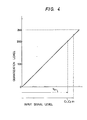
- Fig. 4 is a diagram showing a relation between the input signal level and the quantization level in the A/D converters of Fig. 3, and Figs. 5A and 5B are processing flow charts by the video recording method according to the embodiment of the present invention.
- a maximum input level (Yin) of luminance signal Y is so controlled that the quantization level after the A/D conversion will not become greater than 200 (to obtain a level allotted by the CCIR recommendation).
- maximum input levels (C 1 in, C 2 in) of chrominance signals C 1 , C 2 are so controlled that the quantization level will become 224.
- This table is stored in a ROM (read-only memory) in the code conversion circuit 8 of F ig.
- n max 8(n m ⁇ 6, n r ⁇ 4, n s ⁇ 4) are employed and are stored in the ROM's of code conversion circuits 9, 10 of Fig. 3,respectively (block 22 of Fig. 5A).
- Video signals R, G, B which represent red, green and blue colors of the subject are then produced by the camera and are input to the matrix circuit 4 (block 31 of Fig. 5B) which produces luminance signal Y and chrominance signals C 1 , C 2 (block 32 of Fig. 5B).
- These signals Y, C 1 and C 2 are converted through the A/D converters into digital signals of natural binary codes each consisting of eight bits (block 33 of Fig. 5B).
- These digital signals are converted into digital signals of codes in which continuous numbers of the 0's and the 1's have been limited (block 34 of Fig. 5B) by the 8-8 mapping tables that have been prepared in advance.
- Codes of the thus converted digital signals are inverted on every other sample, and are recorded by recording amplifiers 11, 12, 13 onto a recording medium such as a magnetic tape in the NRZ form via heads 14, 15 and 16 (block 35 of Fig. 5B).
- Each of the code conversion circuits 8, 9 and 10 has an inverter circuit in which the codes of the signals that have obtained through the code conversion are inverted on every other sample.
- Each of the code conversion circuits 8, 9 and 10 produces the signals of which the codes have been converted and of which the codes have been inverted on every other sample.
- Tables 2 and 3 partly illustrate 8-8 mapping tables for the luminance signal Y and chrominance signals C l , C 2 , according to an embodiment of the present invention.
- the patterns of n max 6 alloted to the level 195 and to the neighboring levels (lower than 195) have six 1's. Therefore, if such patterns are alloted to the levels 196 to 199 that have the number of the 1's the same (six) as, or very close (seven or five) to, the number of the 1's alloted to the level 195 and neighboring levels, d-c components can be prevented from generating by inverting the codes of every other sample in reliance on the correlation of television signals.
- n max 8 (n m ⁇ 6, n r ⁇ 4, n s ⁇ 4) are used for all of the quantization levels 0 to 225.
- n m denotes a continuous number of the same digits that exist in a portion between the first digit and the last digit of the output code pattern
- n s denotes a number of digits as counted from the first digit until a digit different from the first digit of the output code pattern appears
- n r denotes a number of digits as counted from the last digit until a digit different from the last digit of the output code pattern appears
- n 1 denotes the number of the l's that exist in the output code pattern.
- the level 224 and the level 225 in the Table 3 need not be utilized.
- 8-8 mapping tables were used in this embodiment, it is also possible to convert the codes into codes in which the continuous number of the 1's or the 0's is smaller than that of the cases of 8-8 mapping tables, by converting digital data consisting of eight bits into a code consisting of nine bits using an 8-9 mapping table. That is, if code patterns consisting of nine bits are considered by adapting the present invention to the 8-9 conversion, a conversion table can be prepared by preferentially using 9-bit patterns that satisfy n s ⁇ 2, n r S2 and n m ⁇ 5 for 256 quantization levels of input signals using 8-9 mapping tables. That is, it is possible to reduce the continuous number of the l's or the 0's to five or to smaller than five.
- an optimum number N of bits for quantization is 6 to 8. Even in the present invention, it is advantageous to use this value from the standpoint of constituting the conversion mapping.
- the signals to be recorded are converted into patterns in which the 1's or the 0's do not continue by more than a predetermined number before they are recorded, relying upon the 8-8 mapping tables in order to reduce d-c components that generate in carrying out the magnetic recording. Therefore, occurrence of erroneous signals caused by pattern peak shift can be reduced, and the digital magnetic recording can be performed maintaining increased'reliability.
Landscapes
- Engineering & Computer Science (AREA)
- Signal Processing (AREA)
- Multimedia (AREA)
- Signal Processing For Digital Recording And Reproducing (AREA)
- Television Signal Processing For Recording (AREA)
- Dc Digital Transmission (AREA)
Applications Claiming Priority (2)
| Application Number | Priority Date | Filing Date | Title |
|---|---|---|---|
| JP33543/84 | 1984-02-24 | ||
| JP59033543A JP2559354B2 (ja) | 1984-02-24 | 1984-02-24 | ディジタル信号変調方法 |
Publications (3)
| Publication Number | Publication Date |
|---|---|
| EP0155529A2 true EP0155529A2 (de) | 1985-09-25 |
| EP0155529A3 EP0155529A3 (en) | 1988-03-30 |
| EP0155529B1 EP0155529B1 (de) | 1992-05-06 |
Family
ID=12389480
Family Applications (1)
| Application Number | Title | Priority Date | Filing Date |
|---|---|---|---|
| EP85101939A Expired - Lifetime EP0155529B1 (de) | 1984-02-24 | 1985-02-22 | Verfahren und Vorrichtung zur magnetischen Aufzeichnung von Videosignalen |
Country Status (6)
| Country | Link |
|---|---|
| US (1) | US4670797A (de) |
| EP (1) | EP0155529B1 (de) |
| JP (1) | JP2559354B2 (de) |
| KR (1) | KR920004117B1 (de) |
| CA (1) | CA1251558A (de) |
| DE (1) | DE3585964D1 (de) |
Cited By (2)
| Publication number | Priority date | Publication date | Assignee | Title |
|---|---|---|---|---|
| EP0249106A3 (en) * | 1986-06-13 | 1988-08-10 | International Business Machines Corporation | Asymmetric rll coding |
| US10877027B2 (en) | 2016-08-01 | 2020-12-29 | Webb Diagnostics Technologies, Inc. | Device and method for detecting a target analyte |
Families Citing this family (2)
| Publication number | Priority date | Publication date | Assignee | Title |
|---|---|---|---|---|
| JP2583670B2 (ja) * | 1990-12-27 | 1997-02-19 | 三星電子株式会社 | ディジタル信号の記録システムとこれを採用した記録方式 |
| US5424881A (en) | 1993-02-01 | 1995-06-13 | Cirrus Logic, Inc. | Synchronous read channel |
Family Cites Families (13)
| Publication number | Priority date | Publication date | Assignee | Title |
|---|---|---|---|---|
| NL7807503A (nl) * | 1977-07-14 | 1979-01-16 | Indep Broadcasting Authority | Transmissie en/of registratie van digitale signalen. |
| JPS5619506A (en) * | 1979-07-23 | 1981-02-24 | Sony Corp | Code converting method |
| JPS5665311A (en) * | 1979-10-27 | 1981-06-03 | Nippon Telegr & Teleph Corp <Ntt> | Magnetic recording and reproduction system for digital information |
| JPS5665314A (en) * | 1979-11-02 | 1981-06-03 | Sony Corp | Encoder for binary signal |
| US4352129A (en) * | 1980-02-01 | 1982-09-28 | Independent Broadcasting Authority | Digital recording apparatus |
| JPS5831644A (ja) * | 1981-08-19 | 1983-02-24 | Matsushita Electric Ind Co Ltd | 二値情報変調符号化方式 |
| JPS5875950A (ja) * | 1981-10-31 | 1983-05-07 | Sony Corp | 2値データの伝送方法 |
| US4464683A (en) * | 1982-01-12 | 1984-08-07 | Rca Corporation | Digital recording of television components with improved transition spacing |
| US4520401A (en) * | 1982-04-16 | 1985-05-28 | Victor Company Of Japan, Ltd. | Digital video signal recording system and reproducing apparatus |
| JPS58195349A (ja) * | 1982-05-10 | 1983-11-14 | Sony Corp | デジタル変調方式 |
| US4547890A (en) * | 1982-09-28 | 1985-10-15 | Abraham M. Gindi | Apparatus and method for forming d.c. free codes |
| US4484176A (en) * | 1982-11-24 | 1984-11-20 | Storage Technology Corporation | Run length limited data encoder |
| JPS59218068A (ja) * | 1983-05-25 | 1984-12-08 | Matsushita Electric Ind Co Ltd | デイジタル変調方法 |
-
1984
- 1984-02-24 JP JP59033543A patent/JP2559354B2/ja not_active Expired - Lifetime
-
1985
- 1985-02-19 US US06/702,600 patent/US4670797A/en not_active Expired - Lifetime
- 1985-02-21 KR KR1019850001067A patent/KR920004117B1/ko not_active Expired
- 1985-02-22 EP EP85101939A patent/EP0155529B1/de not_active Expired - Lifetime
- 1985-02-22 CA CA000474955A patent/CA1251558A/en not_active Expired
- 1985-02-22 DE DE8585101939T patent/DE3585964D1/de not_active Expired - Lifetime
Cited By (3)
| Publication number | Priority date | Publication date | Assignee | Title |
|---|---|---|---|---|
| EP0249106A3 (en) * | 1986-06-13 | 1988-08-10 | International Business Machines Corporation | Asymmetric rll coding |
| US4949196A (en) * | 1986-06-13 | 1990-08-14 | International Business Machines Corporation | Method and apparatus for asymmetrical RLL coding |
| US10877027B2 (en) | 2016-08-01 | 2020-12-29 | Webb Diagnostics Technologies, Inc. | Device and method for detecting a target analyte |
Also Published As
| Publication number | Publication date |
|---|---|
| EP0155529A3 (en) | 1988-03-30 |
| KR920004117B1 (ko) | 1992-05-25 |
| JP2559354B2 (ja) | 1996-12-04 |
| CA1251558A (en) | 1989-03-21 |
| DE3585964D1 (de) | 1992-06-11 |
| US4670797A (en) | 1987-06-02 |
| KR850006827A (ko) | 1985-10-16 |
| EP0155529B1 (de) | 1992-05-06 |
| JPS60178783A (ja) | 1985-09-12 |
Similar Documents
| Publication | Publication Date | Title |
|---|---|---|
| SU1581230A3 (ru) | Устройство кодировани параметров элементов изображени и устройство декодировани параметров элементов изображени | |
| CA1193016A (en) | Method and apparatus for n-to-m encoding | |
| CA1214543A (en) | System for transmitting and receiving television picture information | |
| KR960004577B1 (ko) | 개량된 블록 부호화에 의한 디지탈 신호의 부호화 장치 | |
| EP0177950A2 (de) | Verfahren zur Kodierung eines digitalen Informationssignals | |
| US5644305A (en) | High-efficiency encoding apparatus and high-efficiency decoding apparatus | |
| EP0501755B1 (de) | Vorrichtung zum Aufzeichnen/Wiedergeben eines Videosignals | |
| EP0558016A2 (de) | Verfahren und Vorrichtung zur Bildsignalkodierung mit merhstufigen Quantisierungnummernbestimmung | |
| JPS61147689A (ja) | テレビジョン信号の高能率符号化装置及び符号化方法 | |
| EP0492537B1 (de) | Informationsaufzeichnungsgerät | |
| EP0555832B1 (de) | Datenmodulations und -demodulationsverfahren und -vorrichtung | |
| EP0553650B1 (de) | Verfahren und Vorrichtung zur Übertragung von komprimierten digitalen Bildsignalen | |
| US5444490A (en) | Television system for transmitting pictures in a digital form | |
| KR0137736B1 (ko) | 디지틀 영상신호의 처리장치 | |
| US5162898A (en) | Color image data compressing apparatus and method | |
| US5043809A (en) | Encoding apparatus | |
| EP0155529B1 (de) | Verfahren und Vorrichtung zur magnetischen Aufzeichnung von Videosignalen | |
| US4885637A (en) | Encoder | |
| US4583074A (en) | Expansion circuit for digital signals | |
| JPS6016777B2 (ja) | 信号伝送方式 | |
| US4698811A (en) | Method and apparatus for generating error correction codes for digitized picture signal recording/reproducing | |
| US4405936A (en) | Method of and arrangement for digitizing a color video signal | |
| US4652942A (en) | Method and system for converting binary data using bit-divided encoding | |
| US5276708A (en) | Coding method for reducing the D.C. component in the data stream of a digital signal | |
| JPH0454415B2 (de) |
Legal Events
| Date | Code | Title | Description |
|---|---|---|---|
| PUAI | Public reference made under article 153(3) epc to a published international application that has entered the european phase |
Free format text: ORIGINAL CODE: 0009012 |
|
| 17P | Request for examination filed |
Effective date: 19850222 |
|
| AK | Designated contracting states |
Designated state(s): DE FR GB NL |
|
| PUAL | Search report despatched |
Free format text: ORIGINAL CODE: 0009013 |
|
| AK | Designated contracting states |
Kind code of ref document: A3 Designated state(s): DE FR GB NL |
|
| 17Q | First examination report despatched |
Effective date: 19891027 |
|
| GRAA | (expected) grant |
Free format text: ORIGINAL CODE: 0009210 |
|
| AK | Designated contracting states |
Kind code of ref document: B1 Designated state(s): DE FR GB NL |
|
| REF | Corresponds to: |
Ref document number: 3585964 Country of ref document: DE Date of ref document: 19920611 |
|
| ET | Fr: translation filed | ||
| PGFP | Annual fee paid to national office [announced via postgrant information from national office to epo] |
Ref country code: FR Payment date: 19930119 Year of fee payment: 9 |
|
| PGFP | Annual fee paid to national office [announced via postgrant information from national office to epo] |
Ref country code: GB Payment date: 19930212 Year of fee payment: 9 |
|
| PGFP | Annual fee paid to national office [announced via postgrant information from national office to epo] |
Ref country code: NL Payment date: 19930228 Year of fee payment: 9 |
|
| PLBE | No opposition filed within time limit |
Free format text: ORIGINAL CODE: 0009261 |
|
| STAA | Information on the status of an ep patent application or granted ep patent |
Free format text: STATUS: NO OPPOSITION FILED WITHIN TIME LIMIT |
|
| PGFP | Annual fee paid to national office [announced via postgrant information from national office to epo] |
Ref country code: DE Payment date: 19930323 Year of fee payment: 9 |
|
| 26N | No opposition filed | ||
| PG25 | Lapsed in a contracting state [announced via postgrant information from national office to epo] |
Ref country code: GB Effective date: 19940222 |
|
| PG25 | Lapsed in a contracting state [announced via postgrant information from national office to epo] |
Ref country code: NL Effective date: 19940901 |
|
| NLV4 | Nl: lapsed or anulled due to non-payment of the annual fee | ||
| GBPC | Gb: european patent ceased through non-payment of renewal fee |
Effective date: 19940222 |
|
| PG25 | Lapsed in a contracting state [announced via postgrant information from national office to epo] |
Ref country code: FR Effective date: 19941031 |
|
| PG25 | Lapsed in a contracting state [announced via postgrant information from national office to epo] |
Ref country code: DE Effective date: 19941101 |
|
| REG | Reference to a national code |
Ref country code: FR Ref legal event code: ST |