EP0155605A2 - Abtauverfahren und Vorrichtung zum Durchführen des genannten Verfahrens - Google Patents
Abtauverfahren und Vorrichtung zum Durchführen des genannten Verfahrens Download PDFInfo
- Publication number
- EP0155605A2 EP0155605A2 EP85102679A EP85102679A EP0155605A2 EP 0155605 A2 EP0155605 A2 EP 0155605A2 EP 85102679 A EP85102679 A EP 85102679A EP 85102679 A EP85102679 A EP 85102679A EP 0155605 A2 EP0155605 A2 EP 0155605A2
- Authority
- EP
- European Patent Office
- Prior art keywords
- cooling
- evaporators
- conduit
- vapour
- evaporator
- Prior art date
- Legal status (The legal status is an assumption and is not a legal conclusion. Google has not performed a legal analysis and makes no representation as to the accuracy of the status listed.)
- Granted
Links
Images


Classifications
-
- F—MECHANICAL ENGINEERING; LIGHTING; HEATING; WEAPONS; BLASTING
- F25—REFRIGERATION OR COOLING; COMBINED HEATING AND REFRIGERATION SYSTEMS; HEAT PUMP SYSTEMS; MANUFACTURE OR STORAGE OF ICE; LIQUEFACTION SOLIDIFICATION OF GASES
- F25B—REFRIGERATION MACHINES, PLANTS OR SYSTEMS; COMBINED HEATING AND REFRIGERATION SYSTEMS; HEAT PUMP SYSTEMS
- F25B47/00—Arrangements for preventing or removing deposits or corrosion, not provided for in another subclass
- F25B47/02—Defrosting cycles
- F25B47/022—Defrosting cycles hot gas defrosting
-
- F—MECHANICAL ENGINEERING; LIGHTING; HEATING; WEAPONS; BLASTING
- F25—REFRIGERATION OR COOLING; COMBINED HEATING AND REFRIGERATION SYSTEMS; HEAT PUMP SYSTEMS; MANUFACTURE OR STORAGE OF ICE; LIQUEFACTION SOLIDIFICATION OF GASES
- F25B—REFRIGERATION MACHINES, PLANTS OR SYSTEMS; COMBINED HEATING AND REFRIGERATION SYSTEMS; HEAT PUMP SYSTEMS
- F25B2400/00—General features or devices for refrigeration machines, plants or systems, combined heating and refrigeration systems or heat-pump systems, i.e. not limited to a particular subgroup of F25B
- F25B2400/04—Refrigeration circuit bypassing means
- F25B2400/0403—Refrigeration circuit bypassing means for the condenser
-
- F—MECHANICAL ENGINEERING; LIGHTING; HEATING; WEAPONS; BLASTING
- F25—REFRIGERATION OR COOLING; COMBINED HEATING AND REFRIGERATION SYSTEMS; HEAT PUMP SYSTEMS; MANUFACTURE OR STORAGE OF ICE; LIQUEFACTION SOLIDIFICATION OF GASES
- F25B—REFRIGERATION MACHINES, PLANTS OR SYSTEMS; COMBINED HEATING AND REFRIGERATION SYSTEMS; HEAT PUMP SYSTEMS
- F25B2400/00—General features or devices for refrigeration machines, plants or systems, combined heating and refrigeration systems or heat-pump systems, i.e. not limited to a particular subgroup of F25B
- F25B2400/04—Refrigeration circuit bypassing means
- F25B2400/0411—Refrigeration circuit bypassing means for the expansion valve or capillary tube
-
- F—MECHANICAL ENGINEERING; LIGHTING; HEATING; WEAPONS; BLASTING
- F25—REFRIGERATION OR COOLING; COMBINED HEATING AND REFRIGERATION SYSTEMS; HEAT PUMP SYSTEMS; MANUFACTURE OR STORAGE OF ICE; LIQUEFACTION SOLIDIFICATION OF GASES
- F25B—REFRIGERATION MACHINES, PLANTS OR SYSTEMS; COMBINED HEATING AND REFRIGERATION SYSTEMS; HEAT PUMP SYSTEMS
- F25B2400/00—General features or devices for refrigeration machines, plants or systems, combined heating and refrigeration systems or heat-pump systems, i.e. not limited to a particular subgroup of F25B
- F25B2400/07—Details of compressors or related parts
- F25B2400/075—Details of compressors or related parts with parallel compressors
-
- F—MECHANICAL ENGINEERING; LIGHTING; HEATING; WEAPONS; BLASTING
- F25—REFRIGERATION OR COOLING; COMBINED HEATING AND REFRIGERATION SYSTEMS; HEAT PUMP SYSTEMS; MANUFACTURE OR STORAGE OF ICE; LIQUEFACTION SOLIDIFICATION OF GASES
- F25B—REFRIGERATION MACHINES, PLANTS OR SYSTEMS; COMBINED HEATING AND REFRIGERATION SYSTEMS; HEAT PUMP SYSTEMS
- F25B41/00—Fluid-circulation arrangements
- F25B41/30—Expansion means; Dispositions thereof
- F25B41/385—Dispositions with two or more expansion means arranged in parallel on a refrigerant line leading to the same evaporator
-
- F—MECHANICAL ENGINEERING; LIGHTING; HEATING; WEAPONS; BLASTING
- F25—REFRIGERATION OR COOLING; COMBINED HEATING AND REFRIGERATION SYSTEMS; HEAT PUMP SYSTEMS; MANUFACTURE OR STORAGE OF ICE; LIQUEFACTION SOLIDIFICATION OF GASES
- F25B—REFRIGERATION MACHINES, PLANTS OR SYSTEMS; COMBINED HEATING AND REFRIGERATION SYSTEMS; HEAT PUMP SYSTEMS
- F25B5/00—Compression machines, plants or systems, with several evaporator circuits, e.g. for varying refrigerating capacity
Definitions
- the present invention relates to a method for defrosting one or more evaporators in a cooling system and/or one or more evaporators in a freezing system, whereby cooling-medium liquid is fed to the evaporators of said cooling and freezing systems respectively, via an inlet conduit and evaporated in respective evaporator to cooling-medium vapour, which through an outlet conduit is fed to one or more compressors in the cooling and freezing systems respectively, for compression to heated cooling-medium vapour, which from the compressor or compressors of the cooling system is fed to the evaporator or evaporators of the freezing system for defrosting thereof and from the compressor --or compressors of the-freezing system to the evaporator or evaporators of the cooling system for defrosting thereof.
- the invention also relates to a device for the implementaion of this method.
- Electric defrosting methods are normally used for defrosting evaporators. These methods however, do not permit any quick- defrosting with a reasonable power consumption. Instead, there is a risk that the defrosting time becomes so long, that the products in the cooling and/or freezing plant reach injurious temperatures during the defrosting procedures.
- the object of the present invention is to substantially improve the defrosting capacity at a reduced energy consumption and thereby reduce the defrosting time of the plant. This is arrived at according to the invention by means of the characterizing features of claim 1.
- the object of the invention is also to provide a simple device for the implementation of this method. Such a device has according to the invention, the characterizing features of claim 9.
- the thermal capacity of one or more evaporators may be used for quick- defrosting of one or more other evaporators.
- the defrosting times may be reduced by half compared with those of conventional defrosting methods.
- the present method may be carried out by simple means and furthermore, some previously necessary double arrangements may be reduced to only one arrangement which is common to several systems.
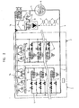
- the cooling and freezing plant of fig. 1 is intended for keeping products in a cooled and frozen condition and includes a cooling system 1 and a freezing system 2 therefor.
- the cooling and freezing plant has a container 3 for cooling-medium liquid 4 which is common to the cooling system 1 and the freezing system 2, said liquid being brought to said systems through a conduit 5.
- cooling-medium liquid is fed to the cooling system 1 via a conduit branch 6 and transferred to a number (e.g. five) of evaporators 7 in the cooling system 1.
- the magnetic valve 8 is provided to, by blocking the conduit 6, prevent injection of cooling-medium liquid into each evaporator 7 during defrosting or prevent delivery of cooling-medium liquid to each evaporators 7 when the desired temperature has been reached in the space to be cooled.
- the expansion valve 9 is provided for injecting the cooling-medium liquid into each evaporator 7. By evaporation of the cooling-medium liquid 4 in the evaporators 7, heat is extracted from the environment. During this heat extraction cooling-medium vapour 10 is produced in the evaporators 7, and this vapour is via the outlets of the evaporators fed to a conduit 11 and through this conduit to a distribution conduit 12.
- compressors 13 are connected to the distribution conduit 12 anddesigned to transform the cooling-medium vapour 10 to heated gas 14 by compression.
- the heated gas 14 is fed through the outlets of the compressors 13 to a connecting conduit 15 common to the cooling and freezing systems and transferring the heated gas to a condenser device 16, which is also common to the cooling and freezing systems.
- a condenser device 16 which is also common to the cooling and freezing systems.
- the heated gas 14 is condensed, and the cooling-medium liquid thereby obtained is fed from the outlet of the condenser 16 through a conduit 17 to the container 3, whereby the circle is closed.
- Cooling-medium liquid 4 is also fed from the container 3 through the conduit 5 and a conduit branch 18 to evaporators 19 (e.g. five) in the freezing system 2.
- the inlet to each evaporator 19 has a magnetic valve 20 and an expansion valve 21 and in each evaporator the cooling-medium liquid is evaporated during extraction of heat from the environment.
- the magnetic valve 20 is provided to, by blocking the conduit 18, prevent injection of cooling-medium liquid into each evaporator 19 during defrosting or prevent delivery of cooling-medium liquid to each evaporator when the desired temperature is obtained in the space to be cooled.
- the expansion valve 21 is provided for injecting the cooling-medium liquid into each evaporator 19.
- each conduit branch 33 may be connected to said conduit 18a as is shown in the drawings. However, if instead of one conduit 18a, several conduits (not shown) lead from the expansion valve 21 to the coils 19a of the evaporator, each conduit branch 33 is preferably divided and each part directly connected to the coils 19a of the evaporator 19. Hereby, it-is possible to-avoid unpermitted restriction of the heated gas before it reaches the coils 19a of the evaporators.
- cooling-medium vapour 10 is produced also here and said vapour is fed through a conduit 22 to a distribution conduit 23.
- Three compressors 24 are connected to the distribution conduit 23 and designed to, by compression, transform the vapour to heated gas 14, which is fed to the common connecting conduit 15 via the outlets of the compressors. Through this common conduit 15, the heated gas from the freezing system is thus also fed to the common condenser 16.
- the common connecting conduit 15 is provided with a valve 25 for deflecting the heated gas 14 through a conduit 26 to a recovery condenser 27.
- This condenser 27 emits heat which may be used for heating premises through air-feed units 28 or for heating water or another medium.
- the outlet of the condenser 27 is through a conduit 29 connected to a separating container 30 for separating gas from liquid if the condenser 27 delivers a mixture of gas and liquid.
- the separated gas is via a conduit 31 returned to the common connecting conduit 15 for condensation in the condenser 16, while the liquid is by-passed the condenser 16 via a conduit 32 and fed to the conduit 17 between the outlet of the condenser 16 and the container 3.
- cooling medium liquid 4 is shown with solid lines along its respective conduits
- cooling-medium vapour 10 is shown with broken lines along its respective lines
- heated gas 14 is shown with dotted and dashed lines along its respective conduits.
- Undercoded cooling-medium liquid 4 is fed from the container 3 through the conduits 5 and 6 to the cooling system evaporators 7,wherein the liquid is evaporated during extraction of heat from the environment.
- the cooling-medium vapour thus produced is fed through the conduit 11 to the distribution conduit 12 for uniform distribution of said vapour to the compressors 13.
- the heated gas 14 generated by the compression of the cooling-medium vapour 10 in the compressors 13, is fed through the common connecting conduit 15 to the condenser 16, wherein, the gas is condensed and the cooling-medium liquid 4 thereby obtained is fed to the container 3.
- the same process occurs with the difference however, that the evaporation temperature in the evaporators of the freezing system is different.
- the capacity of the recovery condenser 27 may be fully used irrespective of the number of compressors loading said condenser and will still permit a low condensing temperature (of e.g. +30 C). If e.g. one of the compressors is in operation, the capacity of the recovery condenser 27 will be sufficiently large to permit full condensation at e.g. +30°C. In this case, the discharge of the recovery condenser 27 merely contains cooling-medium liquid 4 which is fed through the conduit 29 to the separating container 30. Since a float valve in the separating container 30 opens, said liquid may flow through the conduit 32 to the conduit 17 and return to the container 3 therethrough. If e.g.
- each conduit branch 34 may be connected to said conduit 6a as is shown in the drawings. However, if instead of one conduit 6a, several conduits (not shown) lead from the expansion valve 9 to the coils 7a of the evaporator 7, each conduit branch 34 is preferably divided and each part directly connected to the coils of the evaporator.
- the operation of the cooling system 1- is continued as normal operation and the magnetic valve 20 in the conduit 18 is closed such that no cooling-medium liquid 4 is fed to the evaporators 19.
- a magnetic valve 36 in the conduit branch 33 opens, said branch leading from the connecting conduit 15 to the evaporators 19.
- the heated gas 14 from the compressors 13 in the cooling system 1 is fed to the evaporators 19, which means that the heated gas from the cooling system is used for defrosting the evaporators 19 in the freezing system 2.
- the defrosting process described above means that the heat capacity of the cooling system 1 is utilized to quickly defrost the evaporators of the freezing system 2 and that the heat capacity of the freezing system 2 is used to quickly defrost the evaporators of the cooling system 1.
- the defrosting effect of the plant is thus so large that any required defrosting is obtained in four to ten minutes, which is only half the time required for conventional electric defrosting.
- the present defrosting method is obtained in a simple manner by connecting extra conduits 33 and 34 with associated magnetic valves 35 and 36. Furthermore,the defrosting device illustrated in the drawings needs only one condenser for condensing warm gas from both systems and needs only one container for cooling-medium liquid to both systems.
- the upper evaporator 7 in the cooling system 1 shall be defrosted, its magnetic valve 8 is closed such that the flow of cooling-medium liquid thereto is interrupted. Instead, its magnetic valve 35 is opened so that heated gas 14, produced by compression of cooling-medium vapour 10 from the other evaporators 7, may flow into the evaporator in question via the connecting conduit 15 and the extra conduit 34.
- the upper evaporator 19 in the freezing system 2 shall be defrosted, its magnetic valve 20 is closed such that the flow of cooling-medium liquid thereto is cut off. Instead, its magnetic valve 36 is opened so that heated gas 14, produced by compression of cooling-medium vapour 10 from the other evaporators 19, may flow into the evaporator in question via the connecting conduit 15 and the extra conduit 33.
- the method described above is applicable for defrosting combined cooling and freezing systems or for defrosting a separate cooling system 1 or a separate freezing system 2. At all times, it is possible to defrost one, more or all the evaporators.
- warm gas may be transferred between the systems in various ways for defrosting and the devices therefor may be of another type than illustrated.
- Each system may be constructed in other ways than shown; each system may e.g. comprise one, two, three, four, five or more evaporators and one, two, three, four, or more compressors, depending on the desired cooling and freezing capacity respectively,of the plant.
- the method of condensing the warm gas from both systems in a condenser and the device therefor may vary in function and construction, e.g. more than one condenser 16 may be used and the heat recovery system 26, 27, 28, 29, 30, 31 and 32 may be designed in another way or dispensed with if no heat recovery is desired.
Landscapes
- Engineering & Computer Science (AREA)
- Physics & Mathematics (AREA)
- Mechanical Engineering (AREA)
- Thermal Sciences (AREA)
- General Engineering & Computer Science (AREA)
- Defrosting Systems (AREA)
- Greenhouses (AREA)
- Medicines Containing Antibodies Or Antigens For Use As Internal Diagnostic Agents (AREA)
- Organic Low-Molecular-Weight Compounds And Preparation Thereof (AREA)
Priority Applications (1)
| Application Number | Priority Date | Filing Date | Title |
|---|---|---|---|
| AT85102679T ATE55640T1 (de) | 1984-03-21 | 1985-03-08 | Abtauverfahren und vorrichtung zum durchfuehren des genannten verfahrens. |
Applications Claiming Priority (2)
| Application Number | Priority Date | Filing Date | Title |
|---|---|---|---|
| SE8401560 | 1984-03-21 | ||
| SE8401560A SE439831C (sv) | 1984-03-21 | 1984-03-21 | Forfarande och anordning for avfrostning av flera forangare |
Publications (3)
| Publication Number | Publication Date |
|---|---|
| EP0155605A2 true EP0155605A2 (de) | 1985-09-25 |
| EP0155605A3 EP0155605A3 (en) | 1986-08-13 |
| EP0155605B1 EP0155605B1 (de) | 1990-08-16 |
Family
ID=20355226
Family Applications (1)
| Application Number | Title | Priority Date | Filing Date |
|---|---|---|---|
| EP85102679A Expired - Lifetime EP0155605B1 (de) | 1984-03-21 | 1985-03-08 | Abtauverfahren und Vorrichtung zum Durchführen des genannten Verfahrens |
Country Status (9)
| Country | Link |
|---|---|
| US (1) | US4813239A (de) |
| EP (1) | EP0155605B1 (de) |
| JP (1) | JPS60218561A (de) |
| AT (1) | ATE55640T1 (de) |
| DE (1) | DE3579178D1 (de) |
| DK (1) | DK160585B (de) |
| FI (1) | FI851054L (de) |
| NO (1) | NO161877C (de) |
| SE (1) | SE439831C (de) |
Cited By (3)
| Publication number | Priority date | Publication date | Assignee | Title |
|---|---|---|---|---|
| WO1990008931A1 (en) * | 1989-02-06 | 1990-08-09 | Charles Gregory | Hot gas defrost system for refrigeration systems |
| CN107062719A (zh) * | 2017-04-12 | 2017-08-18 | 广东芬尼克兹节能设备有限公司 | 一种双风腔独立除霜控制方法及系统 |
| AT520000A3 (de) * | 2017-05-16 | 2019-01-15 | kke GmbH | Kältemittelkreislauf einer Kälteanlage mit einer Anordnung zum Abtauen eines Wärmeübertragers und Verfahren zum Betreiben des Kältemittelkreislaufs |
Families Citing this family (13)
| Publication number | Priority date | Publication date | Assignee | Title |
|---|---|---|---|---|
| US5042268A (en) * | 1989-11-22 | 1991-08-27 | Labrecque James C | Refrigeration |
| US4945733A (en) * | 1989-11-22 | 1990-08-07 | Labrecque James C | Refrigeration |
| US4979371A (en) * | 1990-01-31 | 1990-12-25 | Hi-Tech Refrigeration, Inc. | Refrigeration system and method involving high efficiency gas defrost of plural evaporators |
| US5031409A (en) * | 1990-07-16 | 1991-07-16 | Tyson Foods, Inc. | Method and apparatus for improving the efficiency of ice production |
| DE4135887A1 (de) * | 1991-10-31 | 1993-05-06 | Wolfram Dr. 4040 Neuss De Seiler | Vorrichtung zum abtauen von kaeltetrocknern unter 0(grad) c |
| US5727453A (en) * | 1994-04-18 | 1998-03-17 | Hjc Beverages, Inc. | Apparatus and method for thawing frozen food product |
| US5669222A (en) * | 1996-06-06 | 1997-09-23 | General Electric Company | Refrigeration passive defrost system |
| WO2002101305A1 (en) * | 2001-06-13 | 2002-12-19 | York Refrigeration Aps | Co2 hot gas defrosting of cascade refrigeration plants |
| US6775993B2 (en) * | 2002-07-08 | 2004-08-17 | Dube Serge | High-speed defrost refrigeration system |
| US7216494B2 (en) * | 2003-10-10 | 2007-05-15 | Matt Alvin Thurman | Supermarket refrigeration system and associated methods |
| WO2006087011A1 (en) * | 2005-02-18 | 2006-08-24 | Carrier Corporation | Co2-refrigeration device with heat reclaim |
| CN101248321A (zh) * | 2005-06-23 | 2008-08-20 | 卡里尔公司 | 对制冷电路中蒸发器进行除霜的方法 |
| JP6688555B2 (ja) * | 2013-11-25 | 2020-04-28 | 三星電子株式会社Samsung Electronics Co.,Ltd. | 空気調和機 |
Family Cites Families (18)
| Publication number | Priority date | Publication date | Assignee | Title |
|---|---|---|---|---|
| US2451682A (en) * | 1946-08-09 | 1948-10-19 | Ole B Lund | Refrigeration system using gas for defrosting |
| GB842231A (en) * | 1957-11-23 | 1960-07-20 | W G G Cuddon Ltd | Improvements in or relating to refrigerating apparatus for foodstuffs |
| US3071935A (en) * | 1959-04-08 | 1963-01-08 | Kapeker Martin | Automatic refrigeration and defrost system |
| US3098363A (en) * | 1961-02-24 | 1963-07-23 | Larkin Coils Inc | Refrigeration system defrosting by controlled flow of gaseous refrigerant |
| FR1423651A (fr) * | 1964-05-14 | 1966-01-07 | Réseau de réfrigération pour installation industrielle | |
| US3301002A (en) * | 1965-04-26 | 1967-01-31 | Carrier Corp | Conditioning apparatus |
| US3580006A (en) * | 1969-04-14 | 1971-05-25 | Lester K Quick | Central refrigeration system with automatic standby compressor capacity |
| US3581519A (en) * | 1969-07-18 | 1971-06-01 | Emhart Corp | Oil equalization system |
| US3645109A (en) * | 1970-03-16 | 1972-02-29 | Lester K Quick | Refrigeration system with hot gas defrosting |
| CA930183A (en) * | 1970-10-30 | 1973-07-17 | Pet Incorporated | Hot gas defrost refrigeration system |
| US3788093A (en) * | 1972-04-21 | 1974-01-29 | Dole Refrigeration Co | Hot gas bypass system for a refrigeration system utilizing a plurality of eutectic plates |
| US4253312A (en) * | 1979-08-27 | 1981-03-03 | Smith Derrick A | Apparatus for the recovery of useful heat from refrigeration gases |
| US4285205A (en) * | 1979-12-20 | 1981-08-25 | Martin Leonard I | Refrigerant sub-cooling |
| US4389851A (en) * | 1980-01-17 | 1983-06-28 | Carrier Corporation | Method for defrosting a heat exchanger of a refrigeration circuit |
| JPS57127756A (en) * | 1981-01-30 | 1982-08-09 | Hitachi Ltd | Refrigerating plant |
| NL188479C (nl) * | 1982-01-28 | 1992-07-01 | Marinus Wilhelmus Matheus Avon | Koelinrichting. |
| US4437317A (en) * | 1982-02-26 | 1984-03-20 | Tyler Refrigeration Corporation | Head pressure maintenance for gas defrost |
| US4554795A (en) * | 1983-11-14 | 1985-11-26 | Tyler Refrigeration Corporation | Compressor oil return system for refrigeration apparatus and method |
-
1984
- 1984-03-21 SE SE8401560A patent/SE439831C/sv not_active IP Right Cessation
-
1985
- 1985-03-08 AT AT85102679T patent/ATE55640T1/de not_active IP Right Cessation
- 1985-03-08 EP EP85102679A patent/EP0155605B1/de not_active Expired - Lifetime
- 1985-03-08 DE DE8585102679T patent/DE3579178D1/de not_active Expired - Lifetime
- 1985-03-15 FI FI851054A patent/FI851054L/fi not_active Application Discontinuation
- 1985-03-20 NO NO851100A patent/NO161877C/no unknown
- 1985-03-20 DK DK126285A patent/DK160585B/da unknown
- 1985-03-22 JP JP60059346A patent/JPS60218561A/ja active Pending
-
1986
- 1986-12-19 US US06/944,374 patent/US4813239A/en not_active Expired - Fee Related
Cited By (5)
| Publication number | Priority date | Publication date | Assignee | Title |
|---|---|---|---|---|
| WO1990008931A1 (en) * | 1989-02-06 | 1990-08-09 | Charles Gregory | Hot gas defrost system for refrigeration systems |
| CN107062719A (zh) * | 2017-04-12 | 2017-08-18 | 广东芬尼克兹节能设备有限公司 | 一种双风腔独立除霜控制方法及系统 |
| CN107062719B (zh) * | 2017-04-12 | 2019-11-01 | 广东芬尼克兹节能设备有限公司 | 一种双风腔独立除霜控制方法及系统 |
| AT520000A3 (de) * | 2017-05-16 | 2019-01-15 | kke GmbH | Kältemittelkreislauf einer Kälteanlage mit einer Anordnung zum Abtauen eines Wärmeübertragers und Verfahren zum Betreiben des Kältemittelkreislaufs |
| AT520000B1 (de) * | 2017-05-16 | 2019-10-15 | kke GmbH | Kältemittelkreislauf einer Kälteanlage mit einer Anordnung zum Abtauen eines Wärmeübertragers und Verfahren zum Betreiben des Kältemittelkreislaufs |
Also Published As
| Publication number | Publication date |
|---|---|
| FI851054A7 (fi) | 1985-09-22 |
| SE439831B (sv) | 1985-07-01 |
| NO851100L (no) | 1985-09-23 |
| DK160585B (da) | 1991-03-25 |
| DE3579178D1 (de) | 1990-09-20 |
| NO161877B (no) | 1989-06-26 |
| NO161877C (no) | 1989-10-04 |
| DK126285D0 (da) | 1985-03-20 |
| SE439831C (sv) | 1987-01-26 |
| ATE55640T1 (de) | 1990-09-15 |
| EP0155605A3 (en) | 1986-08-13 |
| US4813239A (en) | 1989-03-21 |
| EP0155605B1 (de) | 1990-08-16 |
| DK126285A (da) | 1985-09-22 |
| FI851054L (fi) | 1985-09-22 |
| JPS60218561A (ja) | 1985-11-01 |
| SE8401560D0 (sv) | 1984-03-21 |
| FI851054A0 (fi) | 1985-03-15 |
Similar Documents
| Publication | Publication Date | Title |
|---|---|---|
| EP0155605A2 (de) | Abtauverfahren und Vorrichtung zum Durchführen des genannten Verfahrens | |
| US2812642A (en) | Refrigerating apparatus | |
| EP0541343B1 (de) | Kälteanlagen | |
| CN100398948C (zh) | 制冷机 | |
| US3664150A (en) | Hot gas refrigeration defrosting system | |
| US3638444A (en) | Hot gas refrigeration defrost structure and method | |
| US4979371A (en) | Refrigeration system and method involving high efficiency gas defrost of plural evaporators | |
| US3922875A (en) | Refrigeration system with auxiliary defrost heat tank | |
| EP0506365A1 (de) | Kältemittelüberschusssammler für Dampfkompressionkühlkreisläufe mit mehreren Verdampfern | |
| US2492970A (en) | Defrosting system | |
| US2430960A (en) | Refrigeration system including evaporator defrosting means | |
| JPH05500556A (ja) | 熱ガス霜取り式冷凍システム | |
| US4123914A (en) | Energy saving change of phase refrigeration system | |
| US2453033A (en) | Vacuum drying apparatus using a refrigerant system for heating and cooling | |
| US4176526A (en) | Refrigeration system having quick defrost and re-cool | |
| US2309797A (en) | Refrigerating apparatus | |
| US3390540A (en) | Multiple evaporator refrigeration systems | |
| US3234754A (en) | Reevaporator system for hot gas refrigeration defrosting systems | |
| US20180306472A1 (en) | Multi-Stage Oil Batch Boiling System | |
| US2693678A (en) | Automatic defrosting system | |
| US4845954A (en) | Method and device for the manufacture of an ice slurry | |
| US4959971A (en) | Refrigerant piping system for refrigeration equipment | |
| FI92432B (fi) | Kompressiojäähdytysjärjestelmä öljynerottimella | |
| US3060704A (en) | Refrigeration equipment | |
| US2133961A (en) | Refrigeration apparatus |
Legal Events
| Date | Code | Title | Description |
|---|---|---|---|
| PUAI | Public reference made under article 153(3) epc to a published international application that has entered the european phase |
Free format text: ORIGINAL CODE: 0009012 |
|
| AK | Designated contracting states |
Designated state(s): AT BE CH DE FR GB IT LI LU NL SE |
|
| PUAL | Search report despatched |
Free format text: ORIGINAL CODE: 0009013 |
|
| AK | Designated contracting states |
Kind code of ref document: A3 Designated state(s): AT BE CH DE FR GB IT LI LU NL SE |
|
| 17P | Request for examination filed |
Effective date: 19870204 |
|
| 17Q | First examination report despatched |
Effective date: 19871124 |
|
| GRAA | (expected) grant |
Free format text: ORIGINAL CODE: 0009210 |
|
| AK | Designated contracting states |
Kind code of ref document: B1 Designated state(s): AT BE CH DE FR GB IT LI LU NL SE |
|
| PG25 | Lapsed in a contracting state [announced via postgrant information from national office to epo] |
Ref country code: SE Free format text: THE PATENT HAS BEEN ANNULLED BY A DECISION OF A NATIONAL AUTHORITY Effective date: 19900816 Ref country code: NL Effective date: 19900816 Ref country code: BE Effective date: 19900816 Ref country code: AT Effective date: 19900816 |
|
| REF | Corresponds to: |
Ref document number: 55640 Country of ref document: AT Date of ref document: 19900915 Kind code of ref document: T |
|
| ITF | It: translation for a ep patent filed | ||
| REF | Corresponds to: |
Ref document number: 3579178 Country of ref document: DE Date of ref document: 19900920 |
|
| ET | Fr: translation filed | ||
| PG25 | Lapsed in a contracting state [announced via postgrant information from national office to epo] |
Ref country code: GB Effective date: 19910308 |
|
| PG25 | Lapsed in a contracting state [announced via postgrant information from national office to epo] |
Ref country code: LU Free format text: LAPSE BECAUSE OF NON-PAYMENT OF DUE FEES Effective date: 19910331 Ref country code: LI Effective date: 19910331 Ref country code: CH Effective date: 19910331 |
|
| NLV1 | Nl: lapsed or annulled due to failure to fulfill the requirements of art. 29p and 29m of the patents act | ||
| PLBE | No opposition filed within time limit |
Free format text: ORIGINAL CODE: 0009261 |
|
| STAA | Information on the status of an ep patent application or granted ep patent |
Free format text: STATUS: NO OPPOSITION FILED WITHIN TIME LIMIT |
|
| 26N | No opposition filed | ||
| GBPC | Gb: european patent ceased through non-payment of renewal fee | ||
| PG25 | Lapsed in a contracting state [announced via postgrant information from national office to epo] |
Ref country code: FR Effective date: 19911129 |
|
| REG | Reference to a national code |
Ref country code: CH Ref legal event code: PL |
|
| PG25 | Lapsed in a contracting state [announced via postgrant information from national office to epo] |
Ref country code: DE Effective date: 19920101 |
|
| REG | Reference to a national code |
Ref country code: FR Ref legal event code: ST |