EP0155635A2 - Matière composite polymérique moulée - Google Patents
Matière composite polymérique moulée Download PDFInfo
- Publication number
- EP0155635A2 EP0155635A2 EP85102886A EP85102886A EP0155635A2 EP 0155635 A2 EP0155635 A2 EP 0155635A2 EP 85102886 A EP85102886 A EP 85102886A EP 85102886 A EP85102886 A EP 85102886A EP 0155635 A2 EP0155635 A2 EP 0155635A2
- Authority
- EP
- European Patent Office
- Prior art keywords
- resin
- mold
- particles
- basalt
- rock particles
- Prior art date
- Legal status (The legal status is an assumption and is not a legal conclusion. Google has not performed a legal analysis and makes no representation as to the accuracy of the status listed.)
- Withdrawn
Links
Images

Classifications
-
- C—CHEMISTRY; METALLURGY
- C08—ORGANIC MACROMOLECULAR COMPOUNDS; THEIR PREPARATION OR CHEMICAL WORKING-UP; COMPOSITIONS BASED THEREON
- C08K—Use of inorganic or non-macromolecular organic substances as compounding ingredients
- C08K3/00—Use of inorganic substances as compounding ingredients
- C08K3/34—Silicon-containing compounds
-
- F—MECHANICAL ENGINEERING; LIGHTING; HEATING; WEAPONS; BLASTING
- F16—ENGINEERING ELEMENTS AND UNITS; GENERAL MEASURES FOR PRODUCING AND MAINTAINING EFFECTIVE FUNCTIONING OF MACHINES OR INSTALLATIONS; THERMAL INSULATION IN GENERAL
- F16M—FRAMES, CASINGS OR BEDS OF ENGINES, MACHINES OR APPARATUS, NOT SPECIFIC TO ENGINES, MACHINES OR APPARATUS PROVIDED FOR ELSEWHERE; STANDS; SUPPORTS
- F16M5/00—Engine beds, i.e. means for supporting engines or machines on foundations
-
- B—PERFORMING OPERATIONS; TRANSPORTING
- B23—MACHINE TOOLS; METAL-WORKING NOT OTHERWISE PROVIDED FOR
- B23Q—DETAILS, COMPONENTS, OR ACCESSORIES FOR MACHINE TOOLS, e.g. ARRANGEMENTS FOR COPYING OR CONTROLLING; MACHINE TOOLS IN GENERAL CHARACTERISED BY THE CONSTRUCTION OF PARTICULAR DETAILS OR COMPONENTS; COMBINATIONS OR ASSOCIATIONS OF METAL-WORKING MACHINES, NOT DIRECTED TO A PARTICULAR RESULT
- B23Q1/00—Members which are comprised in the general build-up of a form of machine, particularly relatively large fixed members
- B23Q1/01—Frames, beds, pillars or like members; Arrangement of ways
- B23Q1/015—Frames, beds, pillars
-
- B—PERFORMING OPERATIONS; TRANSPORTING
- B28—WORKING CEMENT, CLAY, OR STONE
- B28B—SHAPING CLAY OR OTHER CERAMIC COMPOSITIONS; SHAPING SLAG; SHAPING MIXTURES CONTAINING CEMENTITIOUS MATERIAL, e.g. PLASTER
- B28B23/00—Arrangements specially adapted for the production of shaped articles with elements wholly or partly embedded in the moulding material; Production of reinforced objects
- B28B23/0081—Embedding aggregates to obtain particular properties
-
- B—PERFORMING OPERATIONS; TRANSPORTING
- B29—WORKING OF PLASTICS; WORKING OF SUBSTANCES IN A PLASTIC STATE IN GENERAL
- B29C—SHAPING OR JOINING OF PLASTICS; SHAPING OF MATERIAL IN A PLASTIC STATE, NOT OTHERWISE PROVIDED FOR; AFTER-TREATMENT OF THE SHAPED PRODUCTS, e.g. REPAIRING
- B29C67/00—Shaping techniques not covered by groups B29C39/00 - B29C65/00, B29C70/00 or B29C73/00
- B29C67/24—Shaping techniques not covered by groups B29C39/00 - B29C65/00, B29C70/00 or B29C73/00 characterised by the choice of material
- B29C67/242—Moulding mineral aggregates bonded with resin, e.g. resin concrete
- B29C67/243—Moulding mineral aggregates bonded with resin, e.g. resin concrete for making articles of definite length
-
- C—CHEMISTRY; METALLURGY
- C08—ORGANIC MACROMOLECULAR COMPOUNDS; THEIR PREPARATION OR CHEMICAL WORKING-UP; COMPOSITIONS BASED THEREON
- C08L—COMPOSITIONS OF MACROMOLECULAR COMPOUNDS
- C08L101/00—Compositions of unspecified macromolecular compounds
-
- B—PERFORMING OPERATIONS; TRANSPORTING
- B29—WORKING OF PLASTICS; WORKING OF SUBSTANCES IN A PLASTIC STATE IN GENERAL
- B29L—INDEXING SCHEME ASSOCIATED WITH SUBCLASS B29C, RELATING TO PARTICULAR ARTICLES
- B29L2031/00—Other particular articles
- B29L2031/748—Machines or parts thereof not otherwise provided for
- B29L2031/7502—Supports, machine frames or beds, worktables
-
- Y—GENERAL TAGGING OF NEW TECHNOLOGICAL DEVELOPMENTS; GENERAL TAGGING OF CROSS-SECTIONAL TECHNOLOGIES SPANNING OVER SEVERAL SECTIONS OF THE IPC; TECHNICAL SUBJECTS COVERED BY FORMER USPC CROSS-REFERENCE ART COLLECTIONS [XRACs] AND DIGESTS
- Y10—TECHNICAL SUBJECTS COVERED BY FORMER USPC
- Y10T—TECHNICAL SUBJECTS COVERED BY FORMER US CLASSIFICATION
- Y10T428/00—Stock material or miscellaneous articles
- Y10T428/24—Structurally defined web or sheet [e.g., overall dimension, etc.]
- Y10T428/24942—Structurally defined web or sheet [e.g., overall dimension, etc.] including components having same physical characteristic in differing degree
-
- Y—GENERAL TAGGING OF NEW TECHNOLOGICAL DEVELOPMENTS; GENERAL TAGGING OF CROSS-SECTIONAL TECHNOLOGIES SPANNING OVER SEVERAL SECTIONS OF THE IPC; TECHNICAL SUBJECTS COVERED BY FORMER USPC CROSS-REFERENCE ART COLLECTIONS [XRACs] AND DIGESTS
- Y10—TECHNICAL SUBJECTS COVERED BY FORMER USPC
- Y10T—TECHNICAL SUBJECTS COVERED BY FORMER US CLASSIFICATION
- Y10T428/00—Stock material or miscellaneous articles
- Y10T428/25—Web or sheet containing structurally defined element or component and including a second component containing structurally defined particles
-
- Y—GENERAL TAGGING OF NEW TECHNOLOGICAL DEVELOPMENTS; GENERAL TAGGING OF CROSS-SECTIONAL TECHNOLOGIES SPANNING OVER SEVERAL SECTIONS OF THE IPC; TECHNICAL SUBJECTS COVERED BY FORMER USPC CROSS-REFERENCE ART COLLECTIONS [XRACs] AND DIGESTS
- Y10—TECHNICAL SUBJECTS COVERED BY FORMER USPC
- Y10T—TECHNICAL SUBJECTS COVERED BY FORMER US CLASSIFICATION
- Y10T428/00—Stock material or miscellaneous articles
- Y10T428/31504—Composite [nonstructural laminate]
- Y10T428/31511—Of epoxy ether
-
- Y—GENERAL TAGGING OF NEW TECHNOLOGICAL DEVELOPMENTS; GENERAL TAGGING OF CROSS-SECTIONAL TECHNOLOGIES SPANNING OVER SEVERAL SECTIONS OF THE IPC; TECHNICAL SUBJECTS COVERED BY FORMER USPC CROSS-REFERENCE ART COLLECTIONS [XRACs] AND DIGESTS
- Y10—TECHNICAL SUBJECTS COVERED BY FORMER USPC
- Y10T—TECHNICAL SUBJECTS COVERED BY FORMER US CLASSIFICATION
- Y10T428/00—Stock material or miscellaneous articles
- Y10T428/31504—Composite [nonstructural laminate]
- Y10T428/31786—Of polyester [e.g., alkyd, etc.]
-
- Y—GENERAL TAGGING OF NEW TECHNOLOGICAL DEVELOPMENTS; GENERAL TAGGING OF CROSS-SECTIONAL TECHNOLOGIES SPANNING OVER SEVERAL SECTIONS OF THE IPC; TECHNICAL SUBJECTS COVERED BY FORMER USPC CROSS-REFERENCE ART COLLECTIONS [XRACs] AND DIGESTS
- Y10—TECHNICAL SUBJECTS COVERED BY FORMER USPC
- Y10T—TECHNICAL SUBJECTS COVERED BY FORMER US CLASSIFICATION
- Y10T428/00—Stock material or miscellaneous articles
- Y10T428/31504—Composite [nonstructural laminate]
- Y10T428/31855—Of addition polymer from unsaturated monomers
- Y10T428/31935—Ester, halide or nitrile of addition polymer
Definitions
- This invention relates to a composite for constructing a molded article wherein this composite includes an igneous rock. More particularly, the invention relates to a composite formed primarily of a basalt igneous rock of varying particle sizes surrounded by a solidified epoxy resin to result in a rigid structure having high strength and superior vibration damping properties than previously attained. The invention further relates to a method for forming a composite of such type.
- Other advantages are the utilization of an igneous rock material as represented by basalt in combination with a cycloaliphatic epoxy resin to result in a molded article with high strength and vibration damping properties as well as having a smooth and pleasing appearance as it is released from a mold; a unique composite to which additional filler materials can be added that can be formed into a variety of shapes; a method of making molded articles which is easily performed yet does not require special tooling or handling procedures and will result in a composite having a substantially reduced number of voids therein.
- the present composite for molding an article wherein an igneous rock material in the form of a multiplicity of discrete solid particles with different particle sizes is arranged and compacted in a manner to result in a high degree of rock-to-rock contact such that a minimum number and volume of voids is presented therebetween.
- a solidified plastic material fills the voids between the solid particles providing a bonding material therefor.
- the igneous rock material is a basalt which preferably is present in an amount greater than 70% by volume of the composite and preferably with the resin present in an amount of less than 30% by volume of the composite.
- the bonding material is an epoxy resin of the cycloaliphatic type and particularly is a copolymer of bis (2,3-epoxycyclopentyl) ether and ethylene glycol.
- the particle sizes of the preferred basalt material should be of at least three different sizes so as to be readily compacted with a high degree of rock contact and to result in the minimum amount of voids therebetween.
- a unique method of making an article is also presented wherein a multiplicity of discrete solid particles of an igneous rock material is placed in a mold with the discrete particles being different sizes and compacted in a manner such that a minimum amount of voids are created between the particles.
- a plastic resin material is then flowed around the particles so as to fill the voids and to displace any air therebetween.
- a definite resin-air interface is maintained by introducing the plastic resin at the bottom of the mold and in a direction toward the top.
- both the solid particles and the resin are heated prior to introduction of the resin into the mold. As is well known, resin viscosity is reduced by heating.
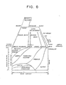
- the preferred aggregate is a variety of basalt having high strength and high modulus. Typical values are:
- basalt differs substantially from granite in both mineral content and grain structure.
- Granite is acidic, whereas basalt is basic.
- basalt was extruded and cooled quickly creating very fine grains.
- Granite on the other hand, was instrusive or slowly cooled forming very large grains and a non-homogeneous structure.
- the coarser grained granite has poorer physical properties than those possessed by the finer grained basalt.
- Basalt is composed largely of the mineral plagioclase feldspar (approximately 85%); lesser minerals include pyrozene and olivine.
- Conspicuously absent from basalt is quartz; granite, however, contains more the 25% quartz. Certain characteristics of basalt and granite are compared in FIGURE 6, wherein the major differences in mineral composition and grain size are illustrated in a three-dimensional graph.
- the crushed basalt utilized in this invention should be graded by particle size and throughly dried in order that the moisture will not be taken up by the polymeric resin thus preventing proper curing.
- storage bins for the crushed aggregate should be provided which will afford the introduction of warm air so as to be passed up through the aggregate in order to effect proper drying.
- vacuum drying of the aggregate could also be utilized with, or as an alternative to, heated air drying. This method would involve evacuating a chamber containing the aggregate to boil off surface moisture. Still a further procedure in drying an aggregate would be to combine it with a drying chemical . such as portland cement.
- cycloaliphatic epoxides are preferred.
- the cycloaliphatic epoxide ERLA-4617 which is available from the Union Carbide Corporation and is the copolymer of bis (2,3-epoxycyclopentyl) ether and ethylene glycol, catalyzed with a tertiary amine.
- Table I indicates the high strength of the ERLA-4617 resin versus a common resin ERLA-2772 which is abisphenol A-epichlorohydrin epoxy resin also available from Union Carbide.
- the basalt is crushed, rinsed in clear water and dried.
- the interior of a suitable mold such as indicated at 10 in FIGURE 4 is previously polished to attain a smooth surface finish.
- the mold in this instance is rectangular and measures 2-7/16 inches in length x 2-5/8 inches in width and 12-1/8 inches in height.
- the mold interior is coated with a suitable mold release compound such as MMS 5050 available from Ecolab, Inc.
- a mixture of resin, curing agent and catalyst is prepared by preheating it to 100 C.
- the basalt aggregates are placed in the previously prepared mold and compacted using a suitable compaction means such as an air hammer.
- the mold and compacted aggregate are then heated to 100°C.
- the prepared fluid resin mixture at 100°C is thereafter placed in a pressurized container and injected through a tube or conduit such as indicated at 16 in., FIGURE 4 using a pressure regulator to control the flow rate.
- the injection pressure is continuously adjusted upwards to a maximum of 10 psig.
- a definite resin-air interface is maintained expelling the air and filling the voids between the solid basalt particles.
- the various sizes of the compacted basalt particles are indicated with the numbers 11,1.2 and 13.
- the numeral 11 indicates the largest sized basalt particles in the -3 ⁇ 4 + 3/8 mesh size
- 12 indicates the intermediate size in the -8 + 16 mesh size
- 13 the smaller size in the -50 + 100 mesh size.
- the numeral 1 4 illustrates the resinous plastic material which surronds the particles resulting in a molded article such as a machine tool component.
- the molded article When the molded article is released from the mold it has a smooth and shining surface with few air pockets or voids. The molded article would require no further preparation before use.
- Example I demonstrates a definite resin-air interface which is maintained by the force of gravity acting upon the resin.
- the definite resin-air interface would be maintained by applying other force fields to the mold, such as a centrifugal force field.
- a centrifugal force field could be created by rotating or otherwise moving the mold.
- the resin would be injected at the outer periphery of the mold.
- Example 2 a cycloaliphatic epoxide compound previously referred to in Table II as ERLA-4617 is employed.
- This particular resin is utilized in the same manner and in the same proportions with the baslt aggregate as indicated in Example 1.
- a suitable curing agent such as the indicated m-phenylenediamine can be employed. All other conditions for introducing the resin and casting of the composite is as previously stated in Example 1.
- FIGURE 4 illustrates one method of introducing the resin material 14 between the different sizes of compacted basalt particles 11-13, wherein the resin material is introduced under pressure from the bottom of the mold through conduit 16. If desired, a mold such as 20 illustrated in FIGURE 5 could be utilized.
- a stationary delivery tube 23 for delivery of resin from the top to the bottom of the mold is coaxilly placed within tube 21.
- the introduction of resin is initially from the bottom of the mold and offers the advantage of air elimination toward the top, the air eventually exiting therefrom as the resin material gradually fills the mold from the bottom.
- the added advantage of mold device 2 0 with retractable delivery tube 23 is the fact that the level of resin is adjustable through the retraction of the tube 2 3 and its selective positioning over apertures 22 for the purpose of gradual resin introduction and air elimination.
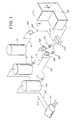
- FIGURE 1 represents a typical layout of a large scale injection station, with high production capacity to produce a molded machine tool member.
- Bulk resin is transferred from tank cars indicated by the numeral 31 through suitable conduits such as 32 and 33 communicating with primary storage tank 34 for resin and tank 30 for the hardener or curing agent.
- the resin and curing agent would be routed through respective lines 35 and 36 by means of pumps 37 to conditioning tanks 38 for conditioning.
- the product is transferred by booster pumps 39 to a proportioning, mixing and dispensing machine 40.
- a suitable coloring pigment is added to the molded product which is stored in tank 45 and delivered to machine 40 through conduits such as 41 and 42 interconnected to conditioning tank 38 and booster pump 39. From there the product is introduced into the aggregate filled mold 41.
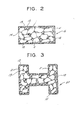
- the finished molded composite is as illustrated in FIGURES 1 and 2 and indicated by the numeral 16 in FIGURE 2 where a rectangular cross section of the composite is particularly shown after it is removed from mold 41.
- FIGURE 3 depicts another geometric configuration as indicated by the numeral 50.
- This particular embodiment simulates a typical I - beam support.
- the basalt particles 17, 12 and 13 in the embodiments of this invention are in a compacted state with a high degree of rock-to-rock contact as well as being surrounded with an adhesive layer of resinous plastic.
- the molded article 16 in FIGURE 2 as it would be produced from the mold 41 in FIGURE 1 is illustrated in the form of a machine tool member and particularly a column and bed.
- the composite of this invention is also capable of being molded into the following machine related components: uprights, saddles, pallets, magazines, spindle heads, belt guards, gear covers and boxes, tool changers, as well as structures for material handling systems.
- the composite can be molded without limitation into'bathtubs, manhole covers, door handles, furniture and construction materials.
- epoxy resins have been illustrated herein wih the cycloaliphtics being preferred.
- bisphenol A-epichlorohydrin eposy resins such as the novolac resins and the linear aliphatic epoxy resins could be employed while still attaining the described advantages.
- epoxy resins have previously been described, other resinous materials with relatively low viscosities which can form the desired bonding between the varying sizes of compacted igneous rock are the polyesters or methacrylates.
- igneous rock in the form of at least three different particle size ranges.
- a plurality of different mesh size ranges as represented by more than three particle size ranges could be utilized with the smaller particle sizes being employed to fill the voids between the larger particles as previously explained.
- the largest particle size should be less than one-third of the wall Lhickness in the region of the component member in which it is placed.
- Flakes and steel fibers as composite reinforcements offer good strength and stiffness. Flake filled composites provide superior vibratory damping; the large number of the polymer layers between the individual flakes, all of which dissipate energy during deformation, is responsible for the high level of damping in flake filled composites..
- the high strength and rigidity of a flake and/or steel fiber filled composite is due to their strength and rigidity as well as their high load acceptance. The high load acceptance is due to their high aspect ratios.
- an important aspect of this invention is the fact that ingneous rocks of varying particle sizes are tightly compressed to compact in the mold device with a high degree of rock-to-rock contact and then surrounded with a solidifiable resinous plastic.
- the present invention provides a unique composite for molding such articles as machine tool components utilizing readily available materials and offering high strength and vibration damping.
- the materials employed are relatively inexpensive thus lending themselves to a low cost composite and final product.
- the product of this invention offers a pleasing appearance as it is removed from the mold having smooth and shining surface of the desired color thus requiring no further preparation prior to use
Landscapes
- Engineering & Computer Science (AREA)
- Mechanical Engineering (AREA)
- Chemical & Material Sciences (AREA)
- Ceramic Engineering (AREA)
- General Engineering & Computer Science (AREA)
- Structural Engineering (AREA)
- Manufacturing & Machinery (AREA)
- Health & Medical Sciences (AREA)
- Chemical Kinetics & Catalysis (AREA)
- Medicinal Chemistry (AREA)
- Polymers & Plastics (AREA)
- Organic Chemistry (AREA)
- Casting Or Compression Moulding Of Plastics Or The Like (AREA)
- Compositions Of Macromolecular Compounds (AREA)
- Machine Tool Units (AREA)
Applications Claiming Priority (2)
| Application Number | Priority Date | Filing Date | Title |
|---|---|---|---|
| US06/592,695 US4784894A (en) | 1984-03-23 | 1984-03-23 | Molded polymer composite |
| US592695 | 1984-03-23 |
Publications (2)
| Publication Number | Publication Date |
|---|---|
| EP0155635A2 true EP0155635A2 (fr) | 1985-09-25 |
| EP0155635A3 EP0155635A3 (fr) | 1987-09-30 |
Family
ID=24371702
Family Applications (1)
| Application Number | Title | Priority Date | Filing Date |
|---|---|---|---|
| EP85102886A Withdrawn EP0155635A3 (fr) | 1984-03-23 | 1985-03-13 | Matière composite polymérique moulée |
Country Status (4)
| Country | Link |
|---|---|
| US (1) | US4784894A (fr) |
| EP (1) | EP0155635A3 (fr) |
| JP (1) | JPS60231450A (fr) |
| KR (1) | KR850006203A (fr) |
Cited By (2)
| Publication number | Priority date | Publication date | Assignee | Title |
|---|---|---|---|---|
| GB2204587A (en) * | 1987-05-15 | 1988-11-16 | Morgan Matroc Limited | Composite polymeric materials containing ceramic particles |
| WO1988009317A1 (fr) * | 1987-05-29 | 1988-12-01 | Explosive Developments Limited | Ameliorations apportees a des explosifs |
Families Citing this family (6)
| Publication number | Priority date | Publication date | Assignee | Title |
|---|---|---|---|---|
| ITTV20020049A1 (it) * | 2002-04-22 | 2003-10-22 | Luca Toncelli | Struttura di sostegno del mandrino in una macchina utensile e procedimento per la sua realizzazione |
| US20100012004A1 (en) * | 2005-06-01 | 2010-01-21 | U.S. Wind Farming Inc. | Basalt particle-containing compositions and articles for protective coatings and ballistic shield mats/tiles/protective building components |
| KR100967633B1 (ko) * | 2008-06-24 | 2010-07-07 | (주)볼케닉스 | 기능성 합성수지 및 그 제조방법 |
| WO2010110906A1 (fr) * | 2009-03-25 | 2010-09-30 | Make It Right Foundation | Béton armé perméable |
| US9260822B2 (en) * | 2012-02-28 | 2016-02-16 | Aggrebind Inc. | Stabilizing agents and methods of use thereof |
| CN117303802A (zh) * | 2023-09-04 | 2023-12-29 | 陕西庄臣环保科技有限公司 | 一种超高强度复合材料及其制备工艺 |
Family Cites Families (24)
| Publication number | Priority date | Publication date | Assignee | Title |
|---|---|---|---|---|
| DE332629C (de) * | 1919-02-05 | 1921-02-03 | Anton Hambloch Dr Ing | Verfahren zur Herstellung von bituminoesen Isoliermassen, Platten u. dgl. |
| CH423911A (de) * | 1963-02-11 | 1966-11-15 | Ciba Geigy | Verfahren zur Herstellung von elektrischen Isolatoren aus einer härtbaren Giessharzmasse mit Füllstoff |
| FR1589444A (fr) * | 1968-05-22 | 1970-03-31 | ||
| GB1300221A (en) * | 1968-10-18 | 1972-12-20 | Philip Henry Morrison | Artificial stone elements-a method of manufacturing same |
| US3554941A (en) * | 1969-03-21 | 1971-01-12 | Concrete Dev Corp | Building material made of a mixture of polyester resin and rice hulls |
| DE2161270A1 (de) * | 1971-08-11 | 1973-02-15 | Transform Roentgen Matern Veb | Verfahren zur herstellung von giessharzumhuellten apparaten |
| DE2229357A1 (de) * | 1972-06-16 | 1974-01-03 | Arthur Otto Richter | Verfahren zur herstellung von elastischen, bruchfesten chemiewerkstein-platten |
| US3856054A (en) * | 1972-07-28 | 1974-12-24 | Atomic Energy Commission | Glass polymer composites |
| NL7313922A (fr) * | 1972-11-15 | 1974-05-17 | ||
| GB1445611A (en) * | 1973-02-07 | 1976-08-11 | Marconi Co Ltd | Electrically conducting arrangements |
| JPS5175750A (ja) * | 1974-12-26 | 1976-06-30 | Sumitomo Electric Industries | Dobokukochikuyozairyososeibutsu |
| CH612610A5 (en) * | 1976-03-23 | 1979-08-15 | Studer Ag Fritz | Machine stand for machine tools |
| GB1486764A (en) * | 1976-07-27 | 1977-09-21 | Standard Telephones Cables Ltd | Cable |
| US4130536A (en) * | 1977-10-13 | 1978-12-19 | Gould Inc. | High humidity resistant electrical grade polymer concrete |
| EP0052166B1 (fr) * | 1978-06-02 | 1986-02-26 | Plastibeton Canada Inc | Procédé de préparation d'un béton lié par un polymère |
| CH641264A5 (de) * | 1979-05-29 | 1984-02-15 | Studer Ag Fritz | Maschinen- apparate- und instrumententeile aus einem gemenge von sand, kies und/oder schotter. |
| US4262889A (en) * | 1979-06-18 | 1981-04-21 | Ford Motor Company | Elastomeric engine mount |
| GB2058736B (en) * | 1979-09-22 | 1983-04-07 | Macmillan Dev Ltd | Structural material |
| GB2071635B (en) * | 1980-02-27 | 1984-02-01 | Inoue Japax Res | Composition of machine tool structural members |
| DE3030914C2 (de) * | 1980-08-16 | 1989-08-10 | Peter 6000 Frankfurt Koblischek | Verfahren zur Herstellung von Maschinenständern mittels Polymerbeton |
| JPS57149884A (en) * | 1981-03-10 | 1982-09-16 | Toyoda Machine Works Ltd | Heat-insulating waterproofing composition for lining of machine tool structure or like |
| US4371639A (en) * | 1981-04-03 | 1983-02-01 | Shell Oil Company | Polyester polymer concrete compositions |
| US4375489A (en) * | 1981-04-03 | 1983-03-01 | Shell Oil Company | Vinyl ester polymer concrete compositions comprising fly ash |
| US4468363A (en) * | 1983-02-02 | 1984-08-28 | Versar Inc. | Internal mold gating method and apparatus |
-
1984
- 1984-03-23 US US06/592,695 patent/US4784894A/en not_active Expired - Lifetime
-
1985
- 1985-03-13 EP EP85102886A patent/EP0155635A3/fr not_active Withdrawn
- 1985-03-22 JP JP60057659A patent/JPS60231450A/ja active Pending
- 1985-03-22 KR KR1019850001889A patent/KR850006203A/ko not_active Withdrawn
Cited By (2)
| Publication number | Priority date | Publication date | Assignee | Title |
|---|---|---|---|---|
| GB2204587A (en) * | 1987-05-15 | 1988-11-16 | Morgan Matroc Limited | Composite polymeric materials containing ceramic particles |
| WO1988009317A1 (fr) * | 1987-05-29 | 1988-12-01 | Explosive Developments Limited | Ameliorations apportees a des explosifs |
Also Published As
| Publication number | Publication date |
|---|---|
| KR850006203A (ko) | 1985-10-02 |
| US4784894A (en) | 1988-11-15 |
| EP0155635A3 (fr) | 1987-09-30 |
| JPS60231450A (ja) | 1985-11-18 |
Similar Documents
| Publication | Publication Date | Title |
|---|---|---|
| US4826127A (en) | Machine supports made from acrylic concrete | |
| US3410936A (en) | Vacuum casting method and apparatus for producing the metal fiber plastic articles | |
| US3917781A (en) | Altering the properties of concrete by altering the quality or geometry of the intergranular contact of filler materials | |
| US2805448A (en) | Method of making composite structural members | |
| US7994235B2 (en) | Method of making models | |
| EP0574247B1 (fr) | Matériau poreux à cellules ouvertes, son procédé de préparation et moule pour moulage sous pression de céramiques fabriqué à partir de ce matériau | |
| EP0155635A2 (fr) | Matière composite polymérique moulée | |
| US4670208A (en) | Method of manufacturing machine supports by means of concrete polymer | |
| US6218458B1 (en) | Method and apparatus for producing gas occlusion-free and void-free compounds and composites | |
| EP0528071B1 (fr) | Procédé de préparation d'une matière poreuse à pores ouvertes | |
| PL167869B1 (pl) | Sposób prózniowego formowania duzych przedmiotów z zywicy syntetycznej PL PL | |
| US6143219A (en) | Method and apparatus for producing gas occlusion-free and void-free compounds and composites | |
| US4920161A (en) | High strength epoxy tooling compositions | |
| KR102479552B1 (ko) | 격자구조 경량골재를 구비하는 콘크리트 및 이의 제조방법 | |
| Calvert et al. | Extrusion methods for solid freeform fabrication | |
| CA2238269C (fr) | Outil composite en polymere ceramique | |
| JP5185564B2 (ja) | 成形物およびその製造方法 | |
| EP3554803B1 (fr) | Procédé de fabrication d'une dalle | |
| CN1064001C (zh) | 一步法生产带有泡沫底层的密实表面材料 | |
| SU1669717A1 (ru) | Способ формовани слоистых бетонных изделий | |
| RU2852665C1 (ru) | Способ изготовления формующей оснастки для производства изделия из полимерных композиционных материалов методом автоклавного формования | |
| FI92984C (fi) | Lasitusmassan muottivalua varten tarkoitettu muotti ja menetelmä muotin valmistamiseksi | |
| Poklemba et al. | Polymer concrete mixtures–application in engineering industry | |
| Kreis | Short curing times for the polymer concrete | |
| FI58881C (fi) | Skaerverktyg foer formgivning av produkter och foerfarande foer dess framstaellning |
Legal Events
| Date | Code | Title | Description |
|---|---|---|---|
| PUAI | Public reference made under article 153(3) epc to a published international application that has entered the european phase |
Free format text: ORIGINAL CODE: 0009012 |
|
| AK | Designated contracting states |
Designated state(s): AT BE CH DE FR GB IT LI LU NL SE |
|
| RBV | Designated contracting states (corrected) |
Designated state(s): CH DE FR GB IT LI NL |
|
| PUAL | Search report despatched |
Free format text: ORIGINAL CODE: 0009013 |
|
| AK | Designated contracting states |
Kind code of ref document: A3 Designated state(s): CH DE FR GB IT LI NL |
|
| 17P | Request for examination filed |
Effective date: 19880317 |
|
| STAA | Information on the status of an ep patent application or granted ep patent |
Free format text: STATUS: THE APPLICATION IS DEEMED TO BE WITHDRAWN |
|
| 18D | Application deemed to be withdrawn |
Effective date: 19891003 |
|
| RIN1 | Information on inventor provided before grant (corrected) |
Inventor name: KIRKHAM, EDWARD E. Inventor name: HUMMELT, EDWARD J. Inventor name: JOHNSTONE, RICHARD |