EP0155657A2 - Grinding apparatus - Google Patents
Grinding apparatus Download PDFInfo
- Publication number
- EP0155657A2 EP0155657A2 EP85103081A EP85103081A EP0155657A2 EP 0155657 A2 EP0155657 A2 EP 0155657A2 EP 85103081 A EP85103081 A EP 85103081A EP 85103081 A EP85103081 A EP 85103081A EP 0155657 A2 EP0155657 A2 EP 0155657A2
- Authority
- EP
- European Patent Office
- Prior art keywords
- rollers
- drive
- machine according
- shredding machine
- housing
- Prior art date
- Legal status (The legal status is an assumption and is not a legal conclusion. Google has not performed a legal analysis and makes no representation as to the accuracy of the status listed.)
- Withdrawn
Links
- 239000000463 material Substances 0.000 claims description 15
- 239000002699 waste material Substances 0.000 abstract description 5
- 238000006073 displacement reaction Methods 0.000 description 3
- 230000000694 effects Effects 0.000 description 2
- 230000001105 regulatory effect Effects 0.000 description 2
- 238000005549 size reduction Methods 0.000 description 2
- 238000010276 construction Methods 0.000 description 1
- 238000011161 development Methods 0.000 description 1
- 230000018109 developmental process Effects 0.000 description 1
- 239000004744 fabric Substances 0.000 description 1
Images


Classifications
-
- B—PERFORMING OPERATIONS; TRANSPORTING
- B02—CRUSHING, PULVERISING, OR DISINTEGRATING; PREPARATORY TREATMENT OF GRAIN FOR MILLING
- B02C—CRUSHING, PULVERISING, OR DISINTEGRATING IN GENERAL; MILLING GRAIN
- B02C4/00—Crushing or disintegrating by roller mills
- B02C4/28—Details
- B02C4/32—Adjusting, applying pressure to, or controlling the distance between, milling members
-
- B—PERFORMING OPERATIONS; TRANSPORTING
- B02—CRUSHING, PULVERISING, OR DISINTEGRATING; PREPARATORY TREATMENT OF GRAIN FOR MILLING
- B02C—CRUSHING, PULVERISING, OR DISINTEGRATING IN GENERAL; MILLING GRAIN
- B02C4/00—Crushing or disintegrating by roller mills
- B02C4/02—Crushing or disintegrating by roller mills with two or more rollers
- B02C4/08—Crushing or disintegrating by roller mills with two or more rollers with co-operating corrugated or toothed crushing-rollers
Definitions
- the invention relates to a shredding machine, in particular for shredding waste, which has the features of the preamble of claim 1.
- the invention has for its object to ensure the passage of larger, non-crushable parts through the crushing rollers and to prevent damage and jamming of the crushing rollers.
- roller pair for fine grinding which is connected downstream of the roller pair for coarse size reduction and has a smaller roller diameter, enables a particularly extensive size reduction of the material.
- rollers from a plurality of gears arranged side by side, one of which is non-rotatably connected to the drive shaft and the other rotatably mounted on the drive shaft, and the interlocking of the non-rotatable with the rotatably mounted gearwheels of two rollers which are in engagement with one another additionally leads to one of the gears caused cutting effect, since they experience a relative change in their angular position depending on the size of the material to be shredded.
- a motor-driven drive chain which is guided over the drive wheels arranged on the drive shafts and drives two co-operating rollers in opposite directions of rotation, simultaneously causes the horizontally displaceable roller to be pressed against the rigidly mounted roller.
- drive wheels are arranged at both ends of the drive shaft. The force pressing the rollers against one another is set by a tensioning device, which acts as a tensioning wheel and acts on the drive chain or the drive belt.
- a chute is arranged horizontally displaceably at a housing outlet opening located below the rollers in order to separate larger, non-crushable parts of the material passing through.
- This chute is controlled automatically by a driver coupled to the slidably mounted roller of the lower pair of rollers.
- two drive shafts 4, 5 are mounted in a stationary bearing holder 2 and a horizontally displaceable bearing holder 3.
- On the drive shaft 4 are six gear wheels 6, 7 arranged in a row, forming a tearing and breaking roller P1, and on the drive shaft 5 six gear wheels 8, 9 forming a counter roller P2.
- one gear 6, which is non-rotatably connected to the drive shaft 4 is arranged next to a gear wheel 7 rotatably mounted on the drive shaft 4.
- the gear wheels 8, 9 forming the roller P2 have a corresponding arrangement.
- Two sprockets 10, 11 are attached to both ends of the drive shafts 4, 5 protruding laterally from the housing 1.
- rollers P1, P2 Two smaller rollers S1, S2 are mounted in a conically tapering, separable housing part 12 of the housing 1. These have a structure corresponding to the structure of the rollers P1, P2.
- the drive shaft 15 of the roller S2 is mounted in a stationary bearing 13 and the drive shaft 16 of the roller S1 in a horizontally displaceable bearing 14.
- the gear wheels 17, 18 forming the roller S2 and the gear wheels 19, 20 forming the roller S1 are also arranged here alternately rotatably and non-rotatably on the shafts 15, 16.
- Two chain wheels 34, 35 are also attached to the outer ends of the drive shafts 15, 16.
- Fastening springs 21 are used for the rotationally fixed attachment of the gears 6, 8, 17, 19 to the drive shafts 4, 5, 15, 16.
- a chute 22 is arranged horizontally displaceably horizontally with the aid of a driver connected to the bearing holder 14. The displacement thus takes place parallel to the displacement of the bearing 14.
- the chute 22 In the position shown of the rollers S1, S2, the chute 22 is in its normal position, in which the comminuted material is discharged to the right at an angle of 45 °. If the rollers S1, S2 are pressed apart as a result of a non-comminutable part of the material passing through, the chute 22 is moved into a position indicated by broken lines, in which a larger non-comminuted part after passing through the rollers S1, S2 is waved from 45 ° to the left. In this way, insufficiently shredded parts can be automatically separated from sufficiently shredded material.
- Guide plates 24 for deflecting the material fed to the rollers P1, P2 are adjustably mounted on both sides of the feed opening 1a.
- a drive shaft 25 mounted on the right outside of the housing 1 in a bearing bracket 26 carries two drive sprockets 27 at each end. At one end of the drive shaft 25, a flywheel 28 is lined up on the drive sprockets 27.
- a drive motor 30 likewise arranged on the outside of the housing 1 drives the flywheel 28 via a V-belt pulley 29 with the aid of a V-belt 37.
- the drive motor 30 is continuously regulated depending on the quantity and / or the consistency of the material comminuted by the rollers P1, P2, S1, S2.
- the drive sprockets 27 drive the drive wheels 10, 11, 34, 35 via four parallel drive chains 36.
- the drive chains 36 are guided over the drive wheels in such a way that they drive the chain wheels 34 and 10 in a clockwise direction and those of the chain wheels 35 and 11 in a counterclockwise direction.
- Tensioning wheels 31 are pressed against the drive chains to generate the necessary chain tension by means of two tensioning arms 32 which are pivotally mounted on the inside of the housing 1 and which are articulated on the piston of a pneumatic pressure cylinder 33.
- the teeth are arranged side by side on a drive shaft of gear wheels not parallel, but offset from one another.
- the material to be shredded falls into the intermediate area from above clear Z between the teeth and be torn or broken between the rollers.
- the roller P2 or S1 is displaced horizontally in the direction of the housing wall against the restoring force of the drive chain. This changes the angular position between the non-rotatably arranged gears and the gears rotatably mounted on the shafts. This leads to a permanent cutting effect of the teeth, so that in particular garbage having a fabric or film structure is cut to a width corresponding to the width of the gearwheels.
- these strip-shaped cut parts pass between the rolls S1, S2 after passing through the rolls P1, P2. These have a higher speed than the rollers P1, P2 because of the smaller chain wheels 34, 35 driving them. In this way, the material cut into strips is drawn faster into the rollers S1, S2 and thereby torn.
- 5 and 6 show the deflection of the roller P2 or the roller S1 during the passage of a larger part of the refuse which is opposed to comminution.
Landscapes
- Engineering & Computer Science (AREA)
- Food Science & Technology (AREA)
- Crushing And Pulverization Processes (AREA)
Abstract
Eine Zerkleinerungsmaschine, insbesondere zur Zerkleinerung von Müll, weist in einem Gehäuse (1) wenigstens zwei durch einen Antriebsmotor (30) gegenläufig angetriebene auf in einer waagrechten Ebene parallel zueinander angeordneten Antriebswellen (4,5 bzw. 15,16) angeordnete Reiß- und Brechwalzen (P1,P2 bzw. S1,S2) auf. Wenigstens eine der Antriebswellen (5,16) ist horizontal gegen die Kraft einer die Walzen (P1,P2,S1,S2) gegeneinander pressenden Spannvorrichtung (31 bis 33) verschiebbar gelagert. Auf diese Weise drücken größere Teile des zu zerkleinernden Mülls die Walzen auseinander und verhindern so ein Beschädigen und Verklemmen der Walzen.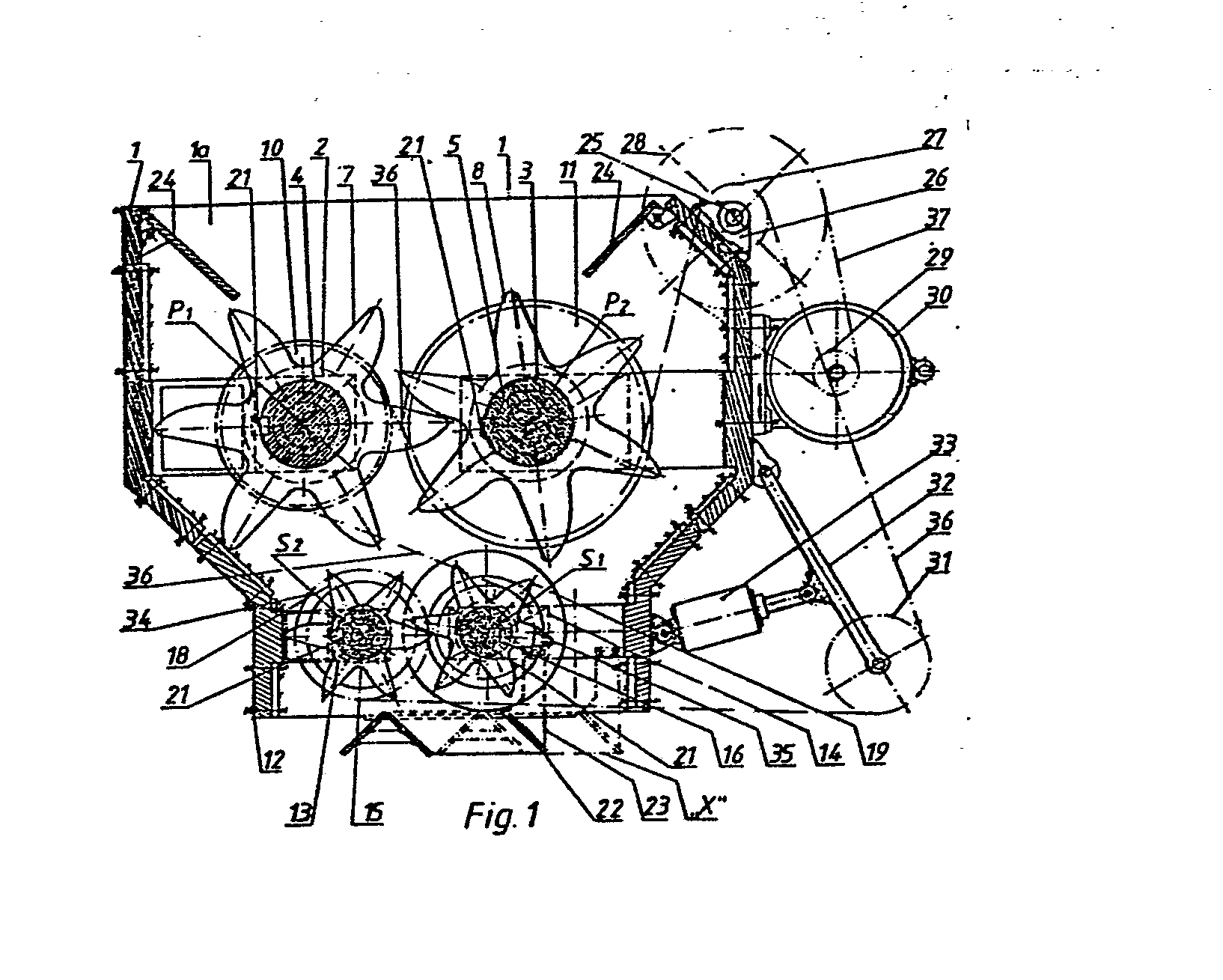
Description
Die Erfindung betrifft eine Zerkleinerungmaschine, insbesondere zur Zerkleinerung von Müll, der die Merkmale des Oberbegriffs des Anspruchs 1 aufweisenden Gattung.The invention relates to a shredding machine, in particular for shredding waste, which has the features of the preamble of
Bekannte MÜllzerkleinerungsmaschinen weisen zwei parallel nebeneinander angeordnete Reiß- und Brechwalzen auf, deren als Haken, Zähne oder dgl. ausgebitdete Reiß- und Brechwerkzeuge sich mit gleicher Winkelgeschwindigkeit drehen. Diese WaLzen können auf Grund ihrer ortsfesten Lagerung durch Teile des zugeführten Materials beschädigt oder verklemmt werden, die sich infolge ihrer Härte oder ihrer Zähigkeit einer ZerkLeinerung widersetzen. Die Entfernung dieser Teile ist mühsam und zeitaufwendig und verringert die Rentabilität der Maschine.Known waste crushing machines have two tearing and breaking rollers arranged side by side in parallel, the tearing and breaking tools designed as hooks, teeth or the like rotate at the same angular speed. Due to their fixed storage, these rollers can be damaged or jammed by parts of the supplied material, which, due to their hardness or toughness, resist crushing. Removing these parts is tedious and time consuming and reduces the profitability of the machine.
Der Erfindung Liegt die Aufgabe zugrunde, den Durchgang von größeren, nicht zerkleinerbaren TeiLen durch die Brechwalzen zu gewährleisten und Beschädigungen sowie ein Verklemmen der Brechwalzen zu verhindern.The invention has for its object to ensure the passage of larger, non-crushable parts through the crushing rollers and to prevent damage and jamming of the crushing rollers.
Diese Aufgabe wird mit Mitteln gelöst, die die kennzeichnenden Merkmale des Anspruchs 1 bilden. Vorteilhafte Weiterbildungen der erfindungsgemäßen ZerkLeinerungsmaschine weisen MerkmaLe auf, wie sie in den Unteransprüchen angegeben sind.This object is achieved by means which form the characterizing features of
Durch die Anordnung eines dem Walzenpaar für die Grobzerkleinerung nachgeschalteten, einen geringeren Walzendurchmesser aufweisenden Walzenpaars zur Feinzerkleinerung wird eine besonders weitgehende ZerkLeinerung des Materials erreicht.The arrangement of a roller pair for fine grinding, which is connected downstream of the roller pair for coarse size reduction and has a smaller roller diameter, enables a particularly extensive size reduction of the material.
Der Aufbau der Walzen aus mehreren nebeneinander angeordneten Zahnrädern, von denen die einen drehfest mit der Antriebswelle verbunden und die anderen drehbeweglich auf der Antriebswelle gelagert sind, und die Verzahnung der drehfesten mit den drehbar gelagerten Zahnrädern zweier im Eingriff miteinander stehenden Walzen führt zusätzlich zu einem von den Zahnrädern bewirkten Schneideffekt, da diese nach Maßgabe der Größe des zu zerkleinernden Guts eine relative Änderung ihrer Winkelstellung erfahren.The construction of the rollers from a plurality of gears arranged side by side, one of which is non-rotatably connected to the drive shaft and the other rotatably mounted on the drive shaft, and the interlocking of the non-rotatable with the rotatably mounted gearwheels of two rollers which are in engagement with one another additionally leads to one of the gears caused cutting effect, since they experience a relative change in their angular position depending on the size of the material to be shredded.
Eine motorisch angetriebene Antriebskette, die über die auf den AntriebsweLLen angeordneten Antriebsräder geführt ist und zwei zusammenwirkende Walzen in einander entgegengesetzem Drehsinn antreibt, bewirkt gleichzeitig, daß die horizontal verschiebbare Walze gegen die starrgelagerte Walze gepreßt wird. Um eine Parallelverschiebung der beweglichen Walze zu gewährleisten, sind an beiden Enden der AntriebsweLLen Antriebsräder angeordnet. Die die Walzen gegeneinander pressende Kraft wird durch eine auf die Antriebskette oder den Antriebsriemen einwirkende, als Spannrad ausgebildete Spannvorrichtung eingestellt.A motor-driven drive chain, which is guided over the drive wheels arranged on the drive shafts and drives two co-operating rollers in opposite directions of rotation, simultaneously causes the horizontally displaceable roller to be pressed against the rigidly mounted roller. In order to ensure a parallel displacement of the movable roller, drive wheels are arranged at both ends of the drive shaft. The force pressing the rollers against one another is set by a tensioning device, which acts as a tensioning wheel and acts on the drive chain or the drive belt.
Zur Aussonderung von größeren, nicht zerkleinerbaren TeiLen des durchlaufenden Materials ist an einer unterhalb der Walzen liegenden Gehäuseaustrittsöffnung eine Schurre horizontal verschiebbar angeordnet. Die Steuerung dieser Schurre erfolgt automatisch über einen mit der verschiebbar gelagerten Walze des unteren Walzenpaars gekuppelten Mitnehmer.A chute is arranged horizontally displaceably at a housing outlet opening located below the rollers in order to separate larger, non-crushable parts of the material passing through. This chute is controlled automatically by a driver coupled to the slidably mounted roller of the lower pair of rollers.
Ein AusführungsbeispieL der Erfindung ist in schematischer Weise in der Zeichnung dargestellt und in der nachfolgenden Beschreibung näher erläutert. Es zeigen
- Fig. 1 einen senkrechten Schnitt durch die Zerkleinerurigsmaschine nach der Schnittlinie A - A der Fig. 2,
- Fig. 2 eine Draufsicht auf die ZerkLeinerungsmaschine und
- Fig. 3 bis 6 verschiedene Arbeitspositionen der Walzen.
- F ig. 1 shows a vertical section through the shredding machine according to section line A - A in FIG. 2,
- Fig. 2 is a plan view of the shredding machine and
- Fig. 3 to 6 different working positions of the rollers.
In einem Gehäuse 1 mit einer am oberen Ende angeordneten öffnung 1a zur Zuführung des zu zerkteinernden Materials wie Müll und dgl. sind in einer ortsfesten Lagerhalterung 2 und einer horizontal verschiebbaren Lagerhalterung 3 zwei Antriebswellen 4,5 gelagert. Auf der Antriebswelle 4 sind sechs aneinander gereihte, eine Reiß- und Brechwalze P1 bildende Zahnrädern 6,7 und auf der Antriebswelle 5 sechs, eine GegenwaLze P2 bildende Zahnrädern 8,9 angeordnet. Jeweils ein drehfest mit der AntriebsweLLe 4 verbundenes Zahnrad 6 ist neben einem drehbar auf der AntriebsweLLe 4 gelagerten Zahnrad 7 angeordnet. Die die Walze P2 bildenden Zahnräder 8,9 weisen eine entsprechende Anordnung auf. Ein drehfest mit der Antriebswelle 4 verbundenes Zahnrad 6 steht jeweils mit einem drehbar gelagerten Zahnrad 9 auf der Antriebswelle 5 und ein drehbar gelagertes Zahnrad 7 auf der Welle 4 mit einem drehfest angeordneten Zahnrad 8 auf der Welle 5 im Eingriff.In a
An beiden aus dem Gehäuse 1 seitlich herausragenden Enden der AntriebsweLLen 4,5 sind je zwei Kettenräder 10,11 angebracht.Two
UnterhaLb der Walzen P1, P2 sind in einem konisch sich verjüngenden, abtrennbaren Gehäuseteil 12 des Gehäuses 1 zwei kleinere Walzen S1, S2 gelagert. Diese weisen einen dem Aufbau der Walzen P1, P2 entsprechenden Aufbau auf. Die Antriebswelle 15 der Walze S2 ist in einem ortsfesten Lager 13 und die Antriebswelle 16 der Walze S1 in einem horizontal verschiebbaren Lager 14 gelagert. Die die Walze S2 bildenden Zahnräder 17,18 sowie die die Walze S1 bildenden Zahnräder 19,20 sind auch hier abwechselnd drehbar und drehfest auf den Wellen 15,16 angeordnet.Below the rollers P1, P2, two smaller rollers S1, S2 are mounted in a conically tapering,
Auch an den äußeren Enden der Antriebswellen 15,16 sind je zwei Kettenräder 34,35 angebracht.Two
Zur drehfesten Anbringung der Zahnräder 6,8,17,19 auf den Antriebswellen 4,5,15,16 dienen Befestigungsfedern 21.Fastening
An der unteren Austrittsöffnung des Gehäuseteils 12 ist eine Schurre 22 horizontal mit HiLfe eines mit der Lagerhalterung 14 verbundenen Mitnehmers horizontal verschiebbar angeordnet. Die Verschiebung erfolgt somit parallel zur Verschiebung des Lagers 14. In der abgebildeten Stellung der Walzen S1,S2 befindet sich die Schurre 22 in ihrer Normalposition, in der das zerkleinerte Material unter einem Winkel von 45° nach rechts abgeleitet wird. Werden die Walzen S1,S2 in FoLge eines nicht zerkteinerbaren Teils des durchLaufenden Materials auseinander gedrückt, so wird die Schurre 22 in eine durch unterbrochene Linien angedeutete Position verschoben, in der ein größeres nicht zerkleinertes Teil nach Durchgang durch die Walzen S1,S2 unter einem Winket von 45° nach Links abgeleitet wird. Auf diese Weise können ungenügend zerkleinerte Teile automatisch von ausreichend zerkleinertem Material getrennt werden.At the lower outlet opening of the
Zu beiden Seiten der Zuführungsöffnung 1a sind Führungsplatten 24 zur UmLenkung des den Walzen P1,P2 zugeführten Materials verstellbar gelagert.
Eine auf der rechten Seite außerhalb des Gehäuses 1 in einer LagerhaLterung 26 gelagerte Antriebswelle 25 trägt an beiden Enden je zwei Antriebskettenräder 27. An einem Ende der Antriebswelle 25 ist auf diese neben den Antriebskettenrädern 27 eine Schwungscheibe 28 aufgereiht. Ein ebenfalls außen am Gehäuse 1 angeordneter Antriebsmotor 30 treibt über eine Keilriemenscheibe 29 mit Hilfe eines Keilriemens 37 die Schwungscheibe 28 an. Der Antriebsmotor 30 wird stufenlos in Abhängigkeit der Menge und/oder der Konsistenz des von den Walzen P1,P2,S1,S2 zerkleinerten Materials geregelt.A
Die Antriebskettenräder 27 treiben über vier parallel verlaufende Antriebsketten 36 die Antriebsräder 10,11,34,35 an. Die Antriebsketten 36 sind so über die Antriebsräder geführt, daß sie die die Kettenräder 34 und 10 im Uhrzeigersinn und die die Kettenräder 35 und 11, im Gegenuhrzeigersinn antreiben. Mittels zweier an der Innenseite des Gehäuses 1 schwenkbar gelagerter, an dem Kolben eines pneumatischen Druckzylinders 33 angelenkter Spannarme 32 werden Spannräder 31 gegen die Antriebsketten zur Erzeugung der notwendigen Kettenspannung gepreßt. Durch Einstellung des Drucks im DruckzyLinder 33 kann die Kettenspannung und damit die durch die Antriebsketten erzeugte, die Walzen P1,P2 einerseits und die Walzen S1,S2 andererseits gegeneinander pressende Kraft geregelt werden.The
Bei den in Fig. 3 dargestellten Walzen sind die Zähne nebeneinander auf einer AntriebsweLLe aufgereihter Zahnräder nicht parallel, sondern gegeneinander versetzt angeordnet. Das zu zerkleinernde Material fällt von oben in die Zwischenräume Z zwischen den Zähnen und wird zwischen den Walzen zerrissen oder gebrochen. Je nach der Größe und der Be- schaffenheit des zwischen die Walzen gelangenden Mülls wird die Walze P2 bzw. S1 horizontal in Richtung auf die Gehäusewand entgegen der Rückstellkraft der Antriebskette verschoben. Dadurch verändert sich die Winkelstellung zwischen den drehfest angeordneten und den drehbar auf den Wellen gelagerten Zahnrädern zueinander. Dies führt zu einer dauernden Schneidwirkung der Zähne, sodaß insbesondere Gewebe- oder Folienstruktur aufweisenden Müll auf eine der Breite der Zahnräder entsprechende Breite zerschnitten wird.In the rollers shown in FIG. 3, the teeth are arranged side by side on a drive shaft of gear wheels not parallel, but offset from one another. The material to be shredded falls into the intermediate area from above clear Z between the teeth and be torn or broken between the rollers. Depending on the size and the nature of the garbage passing between the rollers, the roller P2 or S1 is displaced horizontally in the direction of the housing wall against the restoring force of the drive chain. This changes the angular position between the non-rotatably arranged gears and the gears rotatably mounted on the shafts. This leads to a permanent cutting effect of the teeth, so that in particular garbage having a fabric or film structure is cut to a width corresponding to the width of the gearwheels.
Gemäß Fig. 4 gelangen diese streifenförmig zerschnittenen Teile nach Durchgang durch die Walzen P1,P2 zwischen die Walzen S1, S2. Diese weisen wegen der kleineren sie antreibenden Kettenräder 34,35 eine höhere DrehzahL als die Walzen P1,P2 auf. Auf diese Weise wird das streifenförmig zerschnittene Material schneller in die Walzen S1,S2 hineingezogen und dadurch zerrissen.According to FIG. 4, these strip-shaped cut parts pass between the rolls S1, S2 after passing through the rolls P1, P2. These have a higher speed than the rollers P1, P2 because of the
Die Fig. 5 und 6 zeigen die AusLenkung der Walze P2 bzw. der Walze S1 beim Durchgang eines größeren, einer Zerkleinerung sich widersetzenden Teils des Mülls.5 and 6 show the deflection of the roller P2 or the roller S1 during the passage of a larger part of the refuse which is opposed to comminution.
Claims (14)
Applications Claiming Priority (2)
| Application Number | Priority Date | Filing Date | Title |
|---|---|---|---|
| DE3410053 | 1984-03-19 | ||
| DE19843410053 DE3410053A1 (en) | 1984-03-19 | 1984-03-19 | ASYNCHRONOUS ASTRAL ROTOR REDUCER |
Publications (2)
| Publication Number | Publication Date |
|---|---|
| EP0155657A2 true EP0155657A2 (en) | 1985-09-25 |
| EP0155657A3 EP0155657A3 (en) | 1986-07-30 |
Family
ID=6230970
Family Applications (1)
| Application Number | Title | Priority Date | Filing Date |
|---|---|---|---|
| EP85103081A Withdrawn EP0155657A3 (en) | 1984-03-19 | 1985-03-16 | Grinding apparatus |
Country Status (2)
| Country | Link |
|---|---|
| EP (1) | EP0155657A3 (en) |
| DE (1) | DE3410053A1 (en) |
Cited By (15)
| Publication number | Priority date | Publication date | Assignee | Title |
|---|---|---|---|---|
| ES2154158A1 (en) * | 1998-07-23 | 2001-03-16 | Gomariz Luis Rojas | Container for household organic waste |
| WO2014172947A1 (en) * | 2013-04-24 | 2014-10-30 | Song Chao | Garbage classifying, recycling and treating system and garbage classifying and recycling method |
| WO2014172946A1 (en) * | 2013-04-24 | 2014-10-30 | Song Chao | Garbage crushing system and garbage crushing method |
| CN104550983A (en) * | 2014-12-17 | 2015-04-29 | 范县龙马铜业有限公司 | Material smashing device |
| CN105170229A (en) * | 2015-10-27 | 2015-12-23 | 张荣斌 | Four-roll crusher |
| CN107931306A (en) * | 2017-11-14 | 2018-04-20 | 浙江建设职业技术学院 | A kind of modular kitchen refuse processing apparatus |
| CN108554592A (en) * | 2018-04-27 | 2018-09-21 | 温岭市企浩电子有限公司 | A kind of papery letter box arrangement |
| CN110237893A (en) * | 2019-07-24 | 2019-09-17 | 江苏天鹏机电制造有限公司 | A decoration garbage crushing device |
| CN111036339A (en) * | 2019-12-12 | 2020-04-21 | 安徽汉新环保科技有限公司 | Plastic garbage treatment device for sewage |
| CN112110754A (en) * | 2020-10-27 | 2020-12-22 | 海宁市宁蓝果业科技有限公司 | Preparation method of novel organic fertilizer |
| CN112847961A (en) * | 2021-02-05 | 2021-05-28 | 马超 | Waste plastic film recycling device |
| CN114798111A (en) * | 2022-04-29 | 2022-07-29 | 毅康科技有限公司 | System and method for accurately controlling adding amount of external carbon source |
| CN115591606A (en) * | 2021-07-10 | 2023-01-13 | 龙海建筑科技有限公司(Cn) | A high-efficiency gravel device for landscaping engineering |
| CN118080127A (en) * | 2024-04-12 | 2024-05-28 | 中国二十二冶集团有限公司 | Construction solid waste treatment device and method |
| CN118454870A (en) * | 2024-07-15 | 2024-08-09 | 徐州旺农生物科技有限公司 | Fodder processing raw materials reducing mechanism |
Families Citing this family (4)
| Publication number | Priority date | Publication date | Assignee | Title |
|---|---|---|---|---|
| AU6436990A (en) * | 1989-09-27 | 1991-04-28 | Ecoplastics Limited | Device for chopping garbage |
| DE19508603A1 (en) * | 1995-03-10 | 1996-09-26 | Suedrohrbau Gmbh & Co | Shredder device |
| CN109397576A (en) * | 2018-11-23 | 2019-03-01 | 安徽骏泰塑业科技有限公司 | A kind of PVC pipe multistage grinder |
| CN112337625A (en) * | 2020-10-16 | 2021-02-09 | 安徽沃园生物科技有限公司 | Novel efficient fertilizer crushing apparatus |
Family Cites Families (9)
| Publication number | Priority date | Publication date | Assignee | Title |
|---|---|---|---|---|
| DE665344C (en) * | 1938-09-22 | Auguste Frerotte | Muellereiwalzenstuhl | |
| FR322360A (en) * | 1902-06-21 | 1903-02-03 | Valera Y Valera Jose | Grinding machine, referred to as "cycloid-crusher" |
| GB191218629A (en) * | 1912-08-14 | 1913-02-06 | Charles John Mather | Improvements in or connected with Machines for Breaking or Granulating Friable Material. |
| CH119931A (en) * | 1926-08-11 | 1927-09-01 | Bucher Guyer Ag Masch | Fruit mill. |
| US2562282A (en) * | 1946-01-19 | 1951-07-31 | Frank H Nickle | Two-roll type crusher-feeder |
| US2457632A (en) * | 1946-06-25 | 1948-12-28 | K & B Mfg Co | Belt driven roller mill with adjustably and yieldably mounted roller |
| FR1115823A (en) * | 1954-12-10 | 1956-04-30 | Further training in roller mills | |
| DE1239918B (en) * | 1961-03-22 | 1967-05-03 | Weserhuette Ag Eisenwerk | Attachment of the drive pulleys of roll crushers |
| US3208677A (en) * | 1963-02-06 | 1965-09-28 | Myron C Hesse | Grain roller mill |
-
1984
- 1984-03-19 DE DE19843410053 patent/DE3410053A1/en not_active Withdrawn
-
1985
- 1985-03-16 EP EP85103081A patent/EP0155657A3/en not_active Withdrawn
Cited By (19)
| Publication number | Priority date | Publication date | Assignee | Title |
|---|---|---|---|---|
| ES2154158A1 (en) * | 1998-07-23 | 2001-03-16 | Gomariz Luis Rojas | Container for household organic waste |
| WO2014172947A1 (en) * | 2013-04-24 | 2014-10-30 | Song Chao | Garbage classifying, recycling and treating system and garbage classifying and recycling method |
| WO2014172946A1 (en) * | 2013-04-24 | 2014-10-30 | Song Chao | Garbage crushing system and garbage crushing method |
| CN104550983A (en) * | 2014-12-17 | 2015-04-29 | 范县龙马铜业有限公司 | Material smashing device |
| CN105170229A (en) * | 2015-10-27 | 2015-12-23 | 张荣斌 | Four-roll crusher |
| CN107931306B (en) * | 2017-11-14 | 2024-06-11 | 浙江建设职业技术学院 | Modular kitchen waste treatment device |
| CN107931306A (en) * | 2017-11-14 | 2018-04-20 | 浙江建设职业技术学院 | A kind of modular kitchen refuse processing apparatus |
| CN108554592A (en) * | 2018-04-27 | 2018-09-21 | 温岭市企浩电子有限公司 | A kind of papery letter box arrangement |
| CN110237893A (en) * | 2019-07-24 | 2019-09-17 | 江苏天鹏机电制造有限公司 | A decoration garbage crushing device |
| CN111036339A (en) * | 2019-12-12 | 2020-04-21 | 安徽汉新环保科技有限公司 | Plastic garbage treatment device for sewage |
| CN111036339B (en) * | 2019-12-12 | 2022-01-25 | 江苏创栋环保科技有限公司 | Plastic garbage treatment device for sewage |
| CN112110754B (en) * | 2020-10-27 | 2022-03-01 | 海宁市宁蓝果业科技有限公司 | Preparation method of novel organic fertilizer |
| CN112110754A (en) * | 2020-10-27 | 2020-12-22 | 海宁市宁蓝果业科技有限公司 | Preparation method of novel organic fertilizer |
| CN112847961A (en) * | 2021-02-05 | 2021-05-28 | 马超 | Waste plastic film recycling device |
| CN115591606A (en) * | 2021-07-10 | 2023-01-13 | 龙海建筑科技有限公司(Cn) | A high-efficiency gravel device for landscaping engineering |
| CN114798111A (en) * | 2022-04-29 | 2022-07-29 | 毅康科技有限公司 | System and method for accurately controlling adding amount of external carbon source |
| CN114798111B (en) * | 2022-04-29 | 2024-01-26 | 毅康科技有限公司 | A system and method for accurately controlling the dosage of external carbon source |
| CN118080127A (en) * | 2024-04-12 | 2024-05-28 | 中国二十二冶集团有限公司 | Construction solid waste treatment device and method |
| CN118454870A (en) * | 2024-07-15 | 2024-08-09 | 徐州旺农生物科技有限公司 | Fodder processing raw materials reducing mechanism |
Also Published As
| Publication number | Publication date |
|---|---|
| DE3410053A1 (en) | 1985-10-10 |
| EP0155657A3 (en) | 1986-07-30 |
Similar Documents
| Publication | Publication Date | Title |
|---|---|---|
| DE69207097T2 (en) | Two-shaft coarse shredder | |
| DE2525424A1 (en) | SHEARING DEVICE WITH A MEASURING ROLLER | |
| DE3410053A1 (en) | ASYNCHRONOUS ASTRAL ROTOR REDUCER | |
| DE2401340B2 (en) | Wrapping device in a coin wrapping machine | |
| DE3807983C2 (en) | Crushing device | |
| DE2719784C3 (en) | Folding machine designed for folding on the cover | |
| EP3894206B1 (en) | Device having a guillotine device for cutting to length for manufacturing a packaging material product from a fibre starting material and method for manufacturing a packaging material product | |
| EP0037036B1 (en) | Rotary shredding machine for the reduction of waste material | |
| DE3115688A1 (en) | "DEVICE FOR SEPARATING PRODUCTS TO BE SOLVED IN CONTOUR CUT FROM A MATERIAL RAIL" | |
| DE3689792T2 (en) | APPARATUS FOR COLLECTING AND RELIEVING WASTE. | |
| CH604896A5 (en) | Double parallel cutter refuse grinding machine | |
| DE255997C (en) | ||
| DE2720491A1 (en) | OPENER FOR TEXTILE FIBERS | |
| DE69905790T2 (en) | Device for cutting and creasing sheets of cardboard | |
| DE2158868A1 (en) | MACHINE FOR CRUSHING BULK WASTE | |
| DE102021125587B3 (en) | Device and method for aligning sausages | |
| DE3503640A1 (en) | Device for separating refuse into various fractions of particle size | |
| DE69512091T2 (en) | DEVICE FOR DISPOSAL OF RUBBER MATERIAL | |
| EP0686562A1 (en) | Apparatus for tearing and/or opening bags | |
| DE2544963C3 (en) | Device for shredding household waste | |
| DE2925030C2 (en) | Device for shredding waste such as turnings or the like. | |
| DE3310071C1 (en) | Roll crusher with a roll that can be moved out of the way | |
| DE3918729A1 (en) | DEVICE FOR CRUSHING PLASTIC PARTS, ESPECIALLY FOAMED PLASTIC, SUCH AS FOAM | |
| DE4413106C2 (en) | Cutting device for a wood crusher | |
| DE4445439C2 (en) | Device for opening bags |
Legal Events
| Date | Code | Title | Description |
|---|---|---|---|
| PUAI | Public reference made under article 153(3) epc to a published international application that has entered the european phase |
Free format text: ORIGINAL CODE: 0009012 |
|
| AK | Designated contracting states |
Designated state(s): DE FR GB IT SE |
|
| PUAL | Search report despatched |
Free format text: ORIGINAL CODE: 0009013 |
|
| AK | Designated contracting states |
Kind code of ref document: A3 Designated state(s): DE FR GB IT SE |
|
| STAA | Information on the status of an ep patent application or granted ep patent |
Free format text: STATUS: THE APPLICATION IS DEEMED TO BE WITHDRAWN |
|
| 18D | Application deemed to be withdrawn |
Effective date: 19870131 |
|
| RIN1 | Information on inventor provided before grant (corrected) |
Inventor name: TATURA, JOACHIM Inventor name: TATURA, MICHAEL |