EP0155666A2 - Mécanisme de poursuite solaire - Google Patents
Mécanisme de poursuite solaire Download PDFInfo
- Publication number
- EP0155666A2 EP0155666A2 EP85103119A EP85103119A EP0155666A2 EP 0155666 A2 EP0155666 A2 EP 0155666A2 EP 85103119 A EP85103119 A EP 85103119A EP 85103119 A EP85103119 A EP 85103119A EP 0155666 A2 EP0155666 A2 EP 0155666A2
- Authority
- EP
- European Patent Office
- Prior art keywords
- solar
- sun
- rotating shaft
- rotating
- secured
- Prior art date
- Legal status (The legal status is an assumption and is not a legal conclusion. Google has not performed a legal analysis and makes no representation as to the accuracy of the status listed.)
- Granted
Links
Images


Classifications
-
- G—PHYSICS
- G01—MEASURING; TESTING
- G01S—RADIO DIRECTION-FINDING; RADIO NAVIGATION; DETERMINING DISTANCE OR VELOCITY BY USE OF RADIO WAVES; LOCATING OR PRESENCE-DETECTING BY USE OF THE REFLECTION OR RERADIATION OF RADIO WAVES; ANALOGOUS ARRANGEMENTS USING OTHER WAVES
- G01S3/00—Direction-finders for determining the direction from which infrasonic, sonic, ultrasonic or electromagnetic waves, or particle emission, not having a directional significance, are being received
- G01S3/78—Direction-finders for determining the direction from which infrasonic, sonic, ultrasonic or electromagnetic waves, or particle emission, not having a directional significance, are being received using electromagnetic waves other than radio waves
- G01S3/782—Systems for determining direction or deviation from predetermined direction
- G01S3/785—Systems for determining direction or deviation from predetermined direction using adjustment of orientation of directivity characteristics of a detector or detector system to give a desired condition of signal derived from that detector or detector system
- G01S3/786—Systems for determining direction or deviation from predetermined direction using adjustment of orientation of directivity characteristics of a detector or detector system to give a desired condition of signal derived from that detector or detector system the desired condition being maintained automatically
- G01S3/7861—Solar tracking systems
-
- F—MECHANICAL ENGINEERING; LIGHTING; HEATING; WEAPONS; BLASTING
- F24—HEATING; RANGES; VENTILATING
- F24S—SOLAR HEAT COLLECTORS; SOLAR HEAT SYSTEMS
- F24S30/00—Arrangements for moving or orienting solar heat collector modules
- F24S30/40—Arrangements for moving or orienting solar heat collector modules for rotary movement
- F24S30/42—Arrangements for moving or orienting solar heat collector modules for rotary movement with only one rotation axis
- F24S30/425—Horizontal axis
-
- F—MECHANICAL ENGINEERING; LIGHTING; HEATING; WEAPONS; BLASTING
- F24—HEATING; RANGES; VENTILATING
- F24S—SOLAR HEAT COLLECTORS; SOLAR HEAT SYSTEMS
- F24S50/00—Arrangements for controlling solar heat collectors
- F24S50/20—Arrangements for controlling solar heat collectors for tracking
-
- F—MECHANICAL ENGINEERING; LIGHTING; HEATING; WEAPONS; BLASTING
- F24—HEATING; RANGES; VENTILATING
- F24S—SOLAR HEAT COLLECTORS; SOLAR HEAT SYSTEMS
- F24S30/00—Arrangements for moving or orienting solar heat collector modules
- F24S2030/10—Special components
- F24S2030/13—Transmissions
- F24S2030/134—Transmissions in the form of gearings or rack-and-pinion transmissions
-
- Y—GENERAL TAGGING OF NEW TECHNOLOGICAL DEVELOPMENTS; GENERAL TAGGING OF CROSS-SECTIONAL TECHNOLOGIES SPANNING OVER SEVERAL SECTIONS OF THE IPC; TECHNICAL SUBJECTS COVERED BY FORMER USPC CROSS-REFERENCE ART COLLECTIONS [XRACs] AND DIGESTS
- Y02—TECHNOLOGIES OR APPLICATIONS FOR MITIGATION OR ADAPTATION AGAINST CLIMATE CHANGE
- Y02E—REDUCTION OF GREENHOUSE GAS [GHG] EMISSIONS, RELATED TO ENERGY GENERATION, TRANSMISSION OR DISTRIBUTION
- Y02E10/00—Energy generation through renewable energy sources
- Y02E10/40—Solar thermal energy, e.g. solar towers
- Y02E10/47—Mountings or tracking
Definitions
- This invention relates to a solar tracking mechanism for continuously tracking the movement of the sun with time to effectively obtain radiant energy from the sun.
- Each of the former two U. S. Patents discloses a device which is provided for turning a solar collector about either a polar axis or an east-west horizontal axis.
- the device includes heat responsive elements which exert forces when they are heated by the radiant energy from the sun and become limp when shaded. When the heat responsive element is heated by the solar energy within a certain range of the azimuth or altitude angle, the solar collector can be rotated to a position to face the position of the sun.
- the latter one U. S. Patent also discloses a device which is provided for turning a parabolic trough solar collector about an east-west horizontal axis and the alignment of the solar collector is accomplished by the heating of a long wire held in tension by a spring.
- An object of this invention is to eliminate defects or disadvantages in the prior arts by providing a solar tracking mechanism with no electric power supply and no electric control devices for tracking the sun.
- Another object of this invention is to provide a solar tracking mechanism capable of substantially continuously tracking the sun movement with time even if the sun disappears for relatively long time by utilizing a plurality of compound parabolic concentrators arranged in the east-west direction.
- a solar tracking mechanism for continuously tracking the movement of the sun with time secured to a base settled on a ground through a frame and the solar tracking mechanism comprises a solar radiant energy receiver secured to be rotatable about a rotating shaft therefor which is supported by the frame and extends horizontally in the east-west direction, a device for catching the movement of the sun with time, and a mechanism operatively connected to the device for rotating the rotating shaft together with the solar radiant energy receiver.
- the solar radiant energy receiver comprises a parabolic trough reflector or a solar cell module
- the device for catching the movement of the sun comprises a plurality of compound parabolic "concentrators.
- the self solar tracking mechanism is constructed by a solar tracking device attached to the solar radiant energy receiver and preferably composed of the compound parabolic concentrators, so that the movement of the sun can be continuously catched and even in a case where the sun is covered with clouds or disappears, the solar tracking'mechanism can immediately catch the movement of the sun when the sun again appears.
- a solar radiant energy receiver is essentially composed of a parabolic trough reflector 1 and a heat collecting tube 2 disposed on the focal line of the parabolic trough reflector 1.
- the thus composed solar radiant energy receiver is constructed to be rotatable about the central axis of a rotating shaft of the receiver which extends horizontally in the east-west direction.
- the rotating shaft 3 is a supported at its both end portions by bearings 4 disposed in bearing boxes 5 supported by support bases 6 which are generally settled on the ground.
- Shaft seals 7 are disposed at both ends of the rotating shaft 3.
- Heat transfer medium such as heat transfer oil or pressurized hot water is continuously supplied from a heat transfer medium flow-in pipe 8 into the heat collecting tube 2 and discharged through a heat transfer medium flow-out pipe 9.
- a plurality of compound parabolic concentrators 10a, lOb, 10c and 10d in this embodiment are secured to both edge portions of the parabolic trough reflector 1 in parallel to the rotating shaft 3.
- the CPCs of this embodiment act as a radiant energy collector and can concentrate the sollar energy within a range of about an angle 6 on their focal lines, respectively, as shown in FIG. 2.
- shape memory alloy (SMA) coils lla, llb, llc and lld having one ends secured to one ends of the CP C s l0a through 10d as shown in FIG.
- each of the SMA coils lla through lld is treated so that it shrinks into a tightly wound-up coil shape when it is heated and it may be covered with a glass tube, not shown.
- An Ni-Ti alloy wire is preferably used for the SMA coils.
- the other ends of the tension wires 12a through 12d are wound up, through pulleys 13 and 14, on wire drums 16 secured to drive shafts 15 at both sides of the parabolic trough reflector 1.
- each drive shaft 15 On each drive shaft 15 is mounted a.worm gear 17 which is meshed with a worm wheel 18-secured to the bearing box 5 of the base 6.
- the drive shafts 15 are operatively connected to the rotating shaft 3 through bearings 19 and support frames 20 at both ends thereof.
- a counter weight 21 is connected to the reflector 1 through rod like members 21a so that the center of gravity of the structure rotating together with the parabolic trough reflector 1 is always aligned with the central axis of the rotating shaft 3.
- the solar tracking mechanism according to the embodiment of this invention shown in FIGS. 1 through 3 operates as follows.
- the solar energy is collected by the CPCs 10a and 10c secured to the upper edge of the reflector 1 and concentrated on their focal lines at which the SMA coils lla and llc are positioned.
- the SMA coils lla and llc are then heated and shrink in a preliminarily memorized shape of tightly wound-up coil form, and the tension wires 12a and 12c connected to the SMA coils lla and llc are pulled in arrowed directions.X as shown in FIG. 1.
- the tension wires 12a and 12c wound up on the wire drums 16 are wound off thereby to rotate the worm gears 17, and in turn, rotate the whole structure including the parabolic trough reflector 1 and the heat collecting tube 2 through the worm wheels 18 in a direction Y as shown in FIG. 2.
- the direction of the parabolic trough reflector 1 coincides with the direction of the solar radiation, the solar energy is not concentrated on the focal lines of all of the CPCs 10a through 10d and the shrinkage of the SMA wires stop thereby not to further rotate the reflector 1 and the associated structure.
- the CPCs 10b and 10d start to concentrate the solar energy on their focal lines and the solar tracking mechanism of this embodiment is again rotated in a direction Z as shown in FIG. 2 is accordance with the movement of the sun substantially in the same manner as described with respect to the CPCs 10a and 10c.
- the CPCs may be eliminated to one pair thereof, for example, consisting of the CPCs 10a and 10b or 10c and lOd.
- linear Fresnel lens or parabolic trough reflectors will also be used as the CPCs 10a through 10d for a solar tracking mechanism of this invention.
- the CPCs are more suitable for the tracking mechanism because the solar energy collecting range (i.e., angle 6 in FIG. 2) can be taken to be larger than those-of others. Accordingly, even in a case where the sun is covered with the clouds for relatively long hours, the solar tracking mechanism of this invention can immediately track the movement of the sun again when the sun again appears in the solar energy collecting range.
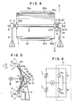
- FIGS. 4 through 6 Another embodiment of this invention will be described hereinafter with reference to FIGS. 4 through 6, in which like reference numerals are added to the elements corresponding to those referred to with respect to the first embodiment shown in FIGS. 1 through 3.
- a pair of compound parabolic concentrators (CPC) 10e and 10f are attached to both longitudinal edge portions of the parabolic trough reflector 1 and solar cell modules 22a and 22b are arranged at portions on the focal lines of the CPCs 10e and 10f, respectively.
- the parabolic trough reflector..1 and the heat collecting tube 2 are held by the rotating shaft 3 in a fixed manner by means of supporting frames 23a and 23b and an arm member 24 is secured to one 23a of these supporting frames so as to project outwardly.
- the arm member 24 holds the drive shaft 25 through the bearing 26.
- the drive shaft 25 On the drive shaft 25 is mounted the worm gear 27, which is in turn meshed with the worm wheel 28, and one end of the drive shaft 25 is operatively coupled with a rotating shaft of a D.C. electric motor 29.
- a counter weight 21 is also provided in this embodiment for the parabolic trough reflector 1 through rod like members 21a so that the gravity center of the structure rotatable together with the reflector 1 is always aligned with the. axis of the rotation of the reflector 1.
- Outputs from the solar cell modules 22a and 22b are transferred to the D.C. motor 29 through electric lead wires 30a and 30b and a switching circuit 31, which is a forward and reversible switching circuit for a direct current of a known type as shown in FIG. 6, for example.
- the switching circuit 31 acts to drive the D.C. motor 29 forwardly or reversely in accordance with the intensity of the output voltage of the solar cell modules 22a and 22b.
- the circuit 31 includes resistors R and transistors TR 1 and TR 2 arranged as shown in FIG. 6.
- the solar tracking mechanism according to the second embodiment of this invention operates as follows.
- the solar energy directed on the surface of the CPC 10e attached to the upper edge portion of the parabolic trough reflector 1 is concentrated on the solar cell module 22a arranged on the focal line of the CPC 10e thereby to raise the output power from the solar module 22a to be extremely larger than that of the solar module 22b located on the focal line of the other CPC 10f secured to the lower edge of the reflector 1.
- the switching circuit 31 connected through the lead wire 30a to the solar cell module 22a then operates to forwardly drive the D.C. motor 29 thereby to rotate the structure including the parabolic trough reflector 1 in a direction X shown in FIG. 5.
- a heat transfer medium such as heat transfer oil or pressurized hot water flows continuously through the heat collecting tube 2 and is continuously heated as far as the sun appears to obtain a high temperature of about 150 - 300°C, which can be utilized for various industrial processes or fields directly after performing effective heat exchanging operation.
- FIGS. 7 and 8 show a further embodiment of a solar tracking mechanism of this invention, in which like reference numerals are added to the elements or members corresponding to those shown in FIGS. 1 through 3 and explanation thereto is now omitted.
- the solar radiant energy receiver comprises a solar cell panel 34 consisting of a plurality of solar cell modules 32 and a support frame 33 for supporting the same.
- the solar cell panel 34 is secured to the rotating shaft 3 through the supporting frame .20 and a pair of compound parabolic concentrators 10a and 10b (CPC) are secured to both the longitudinal edges of the solar cell panel 34 in parallel to the rotating shaft 3.
- CPC compound parabolic concentrators 10a and 10b
- SMA shape memory alloy
- the solar tracking operation or mechanism of this embodiment is substantially the same as that described before with reference to the first embodiment and the electric power from the solar cell modules 32 is externally taken out through a flexible power cable, not shown. It will be of course understood that two pairs of CPCs can be attached to both the longitudinal edges of the solar cell panel 34 as shown in FIG. 1.
- a flat plate solar collector may be used as a solar radiant energy collecting mechanism in place of the sollar cell modules or the parabolic trough reflector.
Landscapes
- Engineering & Computer Science (AREA)
- Physics & Mathematics (AREA)
- Sustainable Development (AREA)
- Life Sciences & Earth Sciences (AREA)
- Sustainable Energy (AREA)
- Thermal Sciences (AREA)
- Chemical & Material Sciences (AREA)
- Combustion & Propulsion (AREA)
- Mechanical Engineering (AREA)
- General Engineering & Computer Science (AREA)
- General Physics & Mathematics (AREA)
- Radar, Positioning & Navigation (AREA)
- Remote Sensing (AREA)
- Electromagnetism (AREA)
- Photovoltaic Devices (AREA)
- Mounting And Adjusting Of Optical Elements (AREA)
Applications Claiming Priority (2)
| Application Number | Priority Date | Filing Date | Title |
|---|---|---|---|
| JP59051103A JPS60196548A (ja) | 1984-03-19 | 1984-03-19 | 太陽自動追尾装置 |
| JP51103/84 | 1984-03-19 |
Publications (3)
| Publication Number | Publication Date |
|---|---|
| EP0155666A2 true EP0155666A2 (fr) | 1985-09-25 |
| EP0155666A3 EP0155666A3 (en) | 1987-05-20 |
| EP0155666B1 EP0155666B1 (fr) | 1989-12-20 |
Family
ID=12877471
Family Applications (1)
| Application Number | Title | Priority Date | Filing Date |
|---|---|---|---|
| EP85103119A Expired EP0155666B1 (fr) | 1984-03-19 | 1985-03-18 | Mécanisme de poursuite solaire |
Country Status (4)
| Country | Link |
|---|---|
| US (1) | US4628142A (fr) |
| EP (1) | EP0155666B1 (fr) |
| JP (1) | JPS60196548A (fr) |
| DE (1) | DE3574904D1 (fr) |
Cited By (8)
| Publication number | Priority date | Publication date | Assignee | Title |
|---|---|---|---|---|
| DE3644450A1 (de) * | 1986-12-24 | 1988-07-07 | Michael Prof Dipl I Schoenherr | Vorrichtung zum ausrichten strahlungsempfindlicher flaechen auf stellare strahlungsquellen |
| AU616354B2 (en) * | 1989-06-12 | 1991-10-24 | Ryohei Ito | An apparatus pursuing the sun |
| CN101881258A (zh) * | 2010-06-07 | 2010-11-10 | 云南金隆伟业电子有限公司 | 无源全天候太阳能接收器驱动装置 |
| WO2010033015A3 (fr) * | 2008-09-18 | 2010-12-09 | Mimos Berhad | Appareil de poursuite du soleil pour capteur d'énergie |
| CN101403533B (zh) * | 2008-11-14 | 2011-02-09 | 中国科学院电工研究所 | 一种槽式抛物面太阳能聚光器 |
| ES2354560A1 (es) * | 2011-02-08 | 2011-03-16 | Soluciones Tecnicas Integrales Norland, S.L. | Dispositivo posicionador para captadores cilindro parabólicos y captador cilindro parabólico que incorpora dicho dispositivo posicionador. |
| CN106931667A (zh) * | 2017-03-20 | 2017-07-07 | 温州立意机电科技有限公司 | 极地太阳能接收铜合金机架 |
| CN107062664A (zh) * | 2017-03-27 | 2017-08-18 | 浙江神德新能源有限公司 | 一种用于调节集热器的放置架 |
Families Citing this family (57)
| Publication number | Priority date | Publication date | Assignee | Title |
|---|---|---|---|---|
| US4868379A (en) * | 1988-06-20 | 1989-09-19 | Utility Power Group | Photovoltaic array with two-axis power maximization tracking |
| US4910395A (en) * | 1989-03-03 | 1990-03-20 | Michael Frankel | Optical tracking sensor including a three-sided prismatic light splitter |
| US5374317A (en) | 1990-09-26 | 1994-12-20 | Energy Systems Solar, Incorporated | Multiple reflector concentrator solar electric power system |
| US5632823A (en) * | 1996-01-29 | 1997-05-27 | Sharan; Anand M. | Solar tracking system |
| US5950618A (en) * | 1998-06-30 | 1999-09-14 | Industrial Technology Research Institute | Solar energy baking apparatus |
| US6302099B1 (en) | 1999-09-16 | 2001-10-16 | Mcdermott Patrick P. | Modular solar tracking frame |
| US6363928B1 (en) | 2000-04-04 | 2002-04-02 | Alternative Energy Group, Inc. | Solar collection system |
| US6399874B1 (en) | 2001-01-11 | 2002-06-04 | Charles Dennehy, Jr. | Solar energy module and fresnel lens for use in same |
| US7252084B2 (en) * | 2004-06-28 | 2007-08-07 | Lucent Technologies Inc. | Solar tracking system |
| US7692091B2 (en) * | 2005-09-27 | 2010-04-06 | Karim Altaii | Shape memory alloy motor as incorporated into solar tracking mechanism |
| US7658071B1 (en) | 2005-12-12 | 2010-02-09 | Mcdermott Patrick P | Solfire solar concentrator and pointer structure |
| CN100427846C (zh) * | 2006-04-27 | 2008-10-22 | 吴兴柳 | 固定反射面的线聚焦太阳能装置 |
| US7430077B2 (en) * | 2006-05-27 | 2008-09-30 | Ciralight, Inc. | Solar tracking reflector system for structure lighting |
| US8469023B2 (en) * | 2006-09-27 | 2013-06-25 | Airlight Energy Ip Sa | Radiation collector |
| US20090223510A1 (en) * | 2006-11-22 | 2009-09-10 | Larsen Theodore E | Optimized solar collector |
| WO2009117840A2 (fr) * | 2008-03-28 | 2009-10-01 | Ale Airlight Energy Sa | Capteur cylindro-parabolique pour centrale solaire |
| CH698860A1 (de) * | 2008-05-07 | 2009-11-13 | Airlight Energy Holding Sa | Rinnenkollektor für ein Solarkraftwerk. |
| ES2337121B1 (es) * | 2008-06-26 | 2011-02-09 | Jose Maria Martinez-Val Peñalosa | Colectores solares cilindro-parabolicos equilibrados con tubo absorbedor fijo. |
| US20100051016A1 (en) * | 2008-08-27 | 2010-03-04 | Ammar Danny F | Modular fresnel solar energy collection system |
| US8378281B2 (en) | 2008-10-24 | 2013-02-19 | Suncore Photovoltaics, Inc. | Terrestrial solar tracking photovoltaic array with offset solar cell modules |
| US8188413B2 (en) * | 2008-10-24 | 2012-05-29 | Emcore Solar Power, Inc. | Terrestrial concentrator solar tracking photovoltaic array |
| US8536504B2 (en) | 2008-10-24 | 2013-09-17 | Suncore Photovoltaics, Inc. | Terrestrial solar tracking photovoltaic array with chain drive |
| US8188415B2 (en) | 2008-10-24 | 2012-05-29 | Emcore Solar Power, Inc. | Terrestrial solar tracking photovoltaic array |
| US20100101630A1 (en) * | 2008-10-24 | 2010-04-29 | Emcore Solar Power, Inc. | Terrestrial Solar Tracking Photovoltaic Array with Slew Speed Reducer |
| US8342169B2 (en) * | 2009-01-05 | 2013-01-01 | Kenergy Scientific, Inc. | Reciprocating solar engine with solar reflectors |
| MX2011007715A (es) | 2009-01-22 | 2011-09-28 | Inspired Surgical Technologies Inc | Sistema de rastreo solar controlado, accionado por prealimentacion. |
| EP2391854A4 (fr) | 2009-02-02 | 2017-01-04 | Glasspoint Solar, Inc. | Concentration d'énergie solaire avec des serres |
| US8499756B2 (en) * | 2009-04-30 | 2013-08-06 | SunPoint Technologies, Inc. | Thermal-mechanical positioning for radiation tracking |
| DE102009039021A1 (de) * | 2009-08-28 | 2011-07-21 | Flagsol GmbH, 50678 | Parabolrinnenkollektor |
| IT1396320B1 (it) * | 2009-10-02 | 2012-11-16 | D D S R L | Meccanismo di movimentazione ed impianto solare utilizzante tale meccanismo. |
| CN101783619B (zh) * | 2009-12-14 | 2011-11-16 | 干布太阳能股份有限公司 | 太阳能追日装置结构 |
| CH702469A1 (de) | 2009-12-17 | 2011-06-30 | Airlight Energy Ip Sa | Parabol-Kollektor. |
| CN101813387A (zh) * | 2010-04-27 | 2010-08-25 | 益科博能源科技(上海)有限公司 | 太阳能收集器的太阳跟踪装置 |
| US8453328B2 (en) | 2010-06-01 | 2013-06-04 | Suncore Photovoltaics, Inc. | Methods and devices for assembling a terrestrial solar tracking photovoltaic array |
| US8592738B1 (en) | 2010-07-01 | 2013-11-26 | Suncore Photovoltaics, Inc. | Alignment device for use with a solar tracking photovoltaic array |
| US8701773B2 (en) | 2010-07-05 | 2014-04-22 | Glasspoint Solar, Inc. | Oilfield application of solar energy collection |
| CN103229000B (zh) * | 2010-07-05 | 2016-07-06 | 玻点太阳能有限公司 | 温室的聚光太阳能发电 |
| CN103221756B (zh) | 2010-07-05 | 2016-05-25 | 玻点太阳能有限公司 | 太阳能直接生成蒸汽 |
| WO2012128877A2 (fr) | 2011-02-22 | 2012-09-27 | Glasspoint Solar, Inc. | Concentration d'énergie solaire au moyen de serres |
| WO2012006288A2 (fr) | 2010-07-05 | 2012-01-12 | Glasspoint Solar, Inc. | Stockage d'énergie thermique souterrain d'une chaleur produite par concentration d'énergie solaire |
| US9893223B2 (en) | 2010-11-16 | 2018-02-13 | Suncore Photovoltaics, Inc. | Solar electricity generation system |
| US9184628B2 (en) * | 2011-02-16 | 2015-11-10 | Jeff Carpoff | Portable solar power trailer with rotatable panels |
| CN102857143A (zh) * | 2011-07-01 | 2013-01-02 | 益科博能源科技(上海)有限公司 | 包含太阳跟踪装置的太阳能收集器 |
| US8763601B2 (en) * | 2011-12-29 | 2014-07-01 | Sulas Industries, Inc. | Solar tracker for solar energy devices |
| ES2446690B1 (es) * | 2012-03-15 | 2014-11-07 | Galio Técnicas Energéticas, S.L. | Marquesina-Seguidor solar de un eje |
| ES2446765B1 (es) * | 2012-03-15 | 2014-11-07 | Galio Técnicas Energéticas, S.L. | Seguidor solar de dos ejes |
| US9200799B2 (en) | 2013-01-07 | 2015-12-01 | Glasspoint Solar, Inc. | Systems and methods for selectively producing steam from solar collectors and heaters for processes including enhanced oil recovery |
| US9874359B2 (en) | 2013-01-07 | 2018-01-23 | Glasspoint Solar, Inc. | Systems and methods for selectively producing steam from solar collectors and heaters |
| US9548697B2 (en) * | 2013-02-28 | 2017-01-17 | Wisconsin Alumni Research Foundation | Passive solar tracking system to enhance solar cell output |
| US10065147B2 (en) | 2014-10-23 | 2018-09-04 | Glasspoint Solar, Inc. | Gas purification using solar energy, and associated systems and methods |
| AU2015335752A1 (en) | 2014-10-23 | 2017-05-04 | Glasspoint Solar, Inc. | Heat storage devices for solar steam generation, and associated systems and methods |
| US10727782B2 (en) | 2015-05-12 | 2020-07-28 | Dennis Peet | Schedule-based sun tracker for increasing directness of sun exposure upon a solar panel to improve energy production |
| US10931224B2 (en) | 2016-06-03 | 2021-02-23 | RBI Solar, Inc. | Single axis in-line gearbox modular tracker system |
| US10651782B2 (en) | 2016-06-30 | 2020-05-12 | Solarcity Corporation | Ballasted tracker drive assembly |
| JP6472423B2 (ja) * | 2016-11-02 | 2019-02-20 | 吉信 宮下 | 海水淡水化装置における熱媒体加熱装置 |
| ES2681093B1 (es) * | 2017-02-10 | 2019-07-11 | Ramos Angel Gabriel Ramos | Sistema de transmisión para seguidores solares equilibrados |
| SE542501C2 (en) * | 2017-09-14 | 2020-05-26 | Absolicon Solar Collector Ab | Solar tracking arrangement for controlling parabolic trough solar collectors, and a thermal energy system |
Family Cites Families (8)
| Publication number | Priority date | Publication date | Assignee | Title |
|---|---|---|---|---|
| US3982526A (en) * | 1975-05-20 | 1976-09-28 | The United States Of America As Represented By The United States Energy Research And Development Administration | Turning collectors for solar radiation |
| US4044752A (en) * | 1975-08-01 | 1977-08-30 | The United States Of America As Represented By The United States Energy Research And Development Administration | Solar collector with altitude tracking |
| DE2842084A1 (de) * | 1978-09-27 | 1980-05-08 | Siemens Ag | Automatische nachfuehrung fuer sonnenorientierte systeme |
| US4351319A (en) * | 1979-08-17 | 1982-09-28 | Robbins Jr Roland W | Radiant energy tracker |
| US4262654A (en) * | 1979-08-24 | 1981-04-21 | Ward Carter J | Solar-energy-powered sun tracker |
| US4365616A (en) * | 1980-09-15 | 1982-12-28 | Vandenberg Leonard B | Self-aligning solar collector |
| JPS59119148A (ja) * | 1982-12-27 | 1984-07-10 | Toshiba Corp | ソ−ラコレクタ |
| US4469938A (en) * | 1983-08-18 | 1984-09-04 | Cohen Elie | Solar tracking unit |
-
1984
- 1984-03-19 JP JP59051103A patent/JPS60196548A/ja active Pending
-
1985
- 1985-03-18 EP EP85103119A patent/EP0155666B1/fr not_active Expired
- 1985-03-18 DE DE8585103119T patent/DE3574904D1/de not_active Expired - Lifetime
- 1985-03-18 US US06/712,539 patent/US4628142A/en not_active Expired - Fee Related
Cited By (10)
| Publication number | Priority date | Publication date | Assignee | Title |
|---|---|---|---|---|
| DE3644450A1 (de) * | 1986-12-24 | 1988-07-07 | Michael Prof Dipl I Schoenherr | Vorrichtung zum ausrichten strahlungsempfindlicher flaechen auf stellare strahlungsquellen |
| AU616354B2 (en) * | 1989-06-12 | 1991-10-24 | Ryohei Ito | An apparatus pursuing the sun |
| WO2010033015A3 (fr) * | 2008-09-18 | 2010-12-09 | Mimos Berhad | Appareil de poursuite du soleil pour capteur d'énergie |
| CN101403533B (zh) * | 2008-11-14 | 2011-02-09 | 中国科学院电工研究所 | 一种槽式抛物面太阳能聚光器 |
| CN101881258A (zh) * | 2010-06-07 | 2010-11-10 | 云南金隆伟业电子有限公司 | 无源全天候太阳能接收器驱动装置 |
| ES2354560A1 (es) * | 2011-02-08 | 2011-03-16 | Soluciones Tecnicas Integrales Norland, S.L. | Dispositivo posicionador para captadores cilindro parabólicos y captador cilindro parabólico que incorpora dicho dispositivo posicionador. |
| WO2012107621A1 (fr) * | 2011-02-08 | 2012-08-16 | Soluciones Técnicas Integrales Norland, S.L. | Dispositif de positionnement pour des capteurs cylindro-paraboliques et capteur cylindro-parabolique comprenant un tel dispositif de positionnement |
| CN106931667A (zh) * | 2017-03-20 | 2017-07-07 | 温州立意机电科技有限公司 | 极地太阳能接收铜合金机架 |
| CN107062664A (zh) * | 2017-03-27 | 2017-08-18 | 浙江神德新能源有限公司 | 一种用于调节集热器的放置架 |
| CN107062664B (zh) * | 2017-03-27 | 2019-02-22 | 浙江神德新能源有限公司 | 一种用于调节集热器的放置架 |
Also Published As
| Publication number | Publication date |
|---|---|
| DE3574904D1 (de) | 1990-01-25 |
| JPS60196548A (ja) | 1985-10-05 |
| US4628142A (en) | 1986-12-09 |
| EP0155666A3 (en) | 1987-05-20 |
| EP0155666B1 (fr) | 1989-12-20 |
Similar Documents
| Publication | Publication Date | Title |
|---|---|---|
| EP0155666B1 (fr) | Mécanisme de poursuite solaire | |
| US4098264A (en) | Solar liquid heating apparatus | |
| US4317031A (en) | Central focus solar energy system | |
| US4297521A (en) | Focusing cover solar energy collector apparatus | |
| US6089224A (en) | Apparatus for orientation of solar radiation collectors | |
| US4284839A (en) | Internal refractor focusing solar energy collector apparatus and method | |
| US4203426A (en) | Solar energy converter carousel mounted rack | |
| US4210463A (en) | Multimode solar energy collector and process | |
| US4832002A (en) | Unified heliostat array | |
| US4243018A (en) | Solar energy concentrator | |
| US20100051016A1 (en) | Modular fresnel solar energy collection system | |
| KR20090029587A (ko) | 태양광 발전장치 | |
| EP0113098B1 (fr) | Système de poursuite pour collecteur solaire | |
| CN101201097A (zh) | 驱动采光器东西方向转动的机械传动装置及太阳能系统 | |
| US4269168A (en) | Focusing reflector solar energy collector apparatus and method | |
| US4572160A (en) | Heliotropic solar heat collector system | |
| GB2054829A (en) | A focussing solar collector | |
| US5347986A (en) | Solar powered high pressure steam generator | |
| US4061130A (en) | Solar energy device | |
| CN101728980A (zh) | 太阳能收集器的极轴跟踪装置 | |
| KR100715040B1 (ko) | 태양광 발전장치 | |
| US4161169A (en) | Focussing flat plate solar collector device | |
| CN103890500B (zh) | 包括定日镜和菲涅耳透镜的太阳能集中器 | |
| JP2001201187A (ja) | 太陽熱ボイラー | |
| Anyaka et al. | Improvement of PV systems power output using sun-tracking techniques |
Legal Events
| Date | Code | Title | Description |
|---|---|---|---|
| PUAI | Public reference made under article 153(3) epc to a published international application that has entered the european phase |
Free format text: ORIGINAL CODE: 0009012 |
|
| 17P | Request for examination filed |
Effective date: 19850416 |
|
| AK | Designated contracting states |
Designated state(s): DE FR GB |
|
| PUAL | Search report despatched |
Free format text: ORIGINAL CODE: 0009013 |
|
| AK | Designated contracting states |
Kind code of ref document: A3 Designated state(s): DE FR GB |
|
| 17Q | First examination report despatched |
Effective date: 19880215 |
|
| GRAA | (expected) grant |
Free format text: ORIGINAL CODE: 0009210 |
|
| AK | Designated contracting states |
Kind code of ref document: B1 Designated state(s): DE FR GB |
|
| REF | Corresponds to: |
Ref document number: 3574904 Country of ref document: DE Date of ref document: 19900125 |
|
| ET | Fr: translation filed | ||
| PLBE | No opposition filed within time limit |
Free format text: ORIGINAL CODE: 0009261 |
|
| STAA | Information on the status of an ep patent application or granted ep patent |
Free format text: STATUS: NO OPPOSITION FILED WITHIN TIME LIMIT |
|
| 26N | No opposition filed | ||
| PGFP | Annual fee paid to national office [announced via postgrant information from national office to epo] |
Ref country code: GB Payment date: 19970310 Year of fee payment: 13 |
|
| PGFP | Annual fee paid to national office [announced via postgrant information from national office to epo] |
Ref country code: FR Payment date: 19970313 Year of fee payment: 13 |
|
| PGFP | Annual fee paid to national office [announced via postgrant information from national office to epo] |
Ref country code: DE Payment date: 19970321 Year of fee payment: 13 |
|
| PG25 | Lapsed in a contracting state [announced via postgrant information from national office to epo] |
Ref country code: GB Free format text: LAPSE BECAUSE OF NON-PAYMENT OF DUE FEES Effective date: 19980318 |
|
| PG25 | Lapsed in a contracting state [announced via postgrant information from national office to epo] |
Ref country code: FR Free format text: THE PATENT HAS BEEN ANNULLED BY A DECISION OF A NATIONAL AUTHORITY Effective date: 19980331 |
|
| GBPC | Gb: european patent ceased through non-payment of renewal fee |
Effective date: 19980318 |
|
| PG25 | Lapsed in a contracting state [announced via postgrant information from national office to epo] |
Ref country code: DE Free format text: LAPSE BECAUSE OF NON-PAYMENT OF DUE FEES Effective date: 19981201 |
|
| REG | Reference to a national code |
Ref country code: FR Ref legal event code: ST |