EP0155729A1 - Circuit pour l'exploitation à courant alternatif pour lampes à décharge à haute pression - Google Patents
Circuit pour l'exploitation à courant alternatif pour lampes à décharge à haute pression Download PDFInfo
- Publication number
- EP0155729A1 EP0155729A1 EP85200313A EP85200313A EP0155729A1 EP 0155729 A1 EP0155729 A1 EP 0155729A1 EP 85200313 A EP85200313 A EP 85200313A EP 85200313 A EP85200313 A EP 85200313A EP 0155729 A1 EP0155729 A1 EP 0155729A1
- Authority
- EP
- European Patent Office
- Prior art keywords
- transistor
- lamp
- current
- voltage
- base
- Prior art date
- Legal status (The legal status is an assumption and is not a legal conclusion. Google has not performed a legal analysis and makes no representation as to the accuracy of the status listed.)
- Granted
Links
- 238000004804 winding Methods 0.000 claims abstract description 28
- 239000003990 capacitor Substances 0.000 claims description 18
- 238000009499 grossing Methods 0.000 claims description 11
- 230000000737 periodic effect Effects 0.000 abstract 1
- 229910001507 metal halide Inorganic materials 0.000 description 3
- 150000005309 metal halides Chemical class 0.000 description 3
- 230000010355 oscillation Effects 0.000 description 3
- 230000006378 damage Effects 0.000 description 1
- 230000001419 dependent effect Effects 0.000 description 1
- 230000002349 favourable effect Effects 0.000 description 1
- 238000010438 heat treatment Methods 0.000 description 1
- 238000000034 method Methods 0.000 description 1
Images
Classifications
-
- H—ELECTRICITY
- H05—ELECTRIC TECHNIQUES NOT OTHERWISE PROVIDED FOR
- H05B—ELECTRIC HEATING; ELECTRIC LIGHT SOURCES NOT OTHERWISE PROVIDED FOR; CIRCUIT ARRANGEMENTS FOR ELECTRIC LIGHT SOURCES, IN GENERAL
- H05B41/00—Circuit arrangements or apparatus for igniting or operating discharge lamps
- H05B41/14—Circuit arrangements
- H05B41/26—Circuit arrangements in which the lamp is fed by power derived from DC by means of a converter, e.g. by high-voltage DC
- H05B41/28—Circuit arrangements in which the lamp is fed by power derived from DC by means of a converter, e.g. by high-voltage DC using static converters
- H05B41/288—Circuit arrangements in which the lamp is fed by power derived from DC by means of a converter, e.g. by high-voltage DC using static converters with semiconductor devices and specially adapted for lamps without preheating electrodes, e.g. for high-intensity discharge lamps, high-pressure mercury or sodium lamps or low-pressure sodium lamps
- H05B41/292—Arrangements for protecting lamps or circuits against abnormal operating conditions
- H05B41/2921—Arrangements for protecting lamps or circuits against abnormal operating conditions for protecting the circuit against abnormal operating conditions
- H05B41/2926—Arrangements for protecting lamps or circuits against abnormal operating conditions for protecting the circuit against abnormal operating conditions against internal abnormal circuit conditions
-
- Y—GENERAL TAGGING OF NEW TECHNOLOGICAL DEVELOPMENTS; GENERAL TAGGING OF CROSS-SECTIONAL TECHNOLOGIES SPANNING OVER SEVERAL SECTIONS OF THE IPC; TECHNICAL SUBJECTS COVERED BY FORMER USPC CROSS-REFERENCE ART COLLECTIONS [XRACs] AND DIGESTS
- Y10—TECHNICAL SUBJECTS COVERED BY FORMER USPC
- Y10S—TECHNICAL SUBJECTS COVERED BY FORMER USPC CROSS-REFERENCE ART COLLECTIONS [XRACs] AND DIGESTS
- Y10S315/00—Electric lamp and discharge devices: systems
- Y10S315/07—Starting and control circuits for gas discharge lamp using transistors
Definitions
- the invention relates to a circuit arrangement for AC operation of high-pressure gas discharge lamps with a current limiter arranged between the lamp and the mains AC voltage source and a high-frequency oscillator fed with direct current, which generates a high-frequency current superimposed on the mains AC lamp current through the lamp and an RF transformer and one in series with its primary winding Has lying, periodically on and off transistor, wherein a secondary winding of the transformer is connected in series with the lamp.
- An ohmic resistor, a choke coil or an electronic ballast can be used as the current limiter.
- a problem with the operation of high-pressure gas discharge lamps is the re-ignition after every zero crossing of the AC lamp current.
- high re-ignition voltages may be required during the warm-up phase that the ballast or the like. can no longer be delivered and the lamp therefore goes out.
- the lamps operated from an AC voltage source have therefore been overlaid with an additional high-frequency current.
- a high voltage with a frequency of 1.6 to 200 kHz is additionally applied to ignite the lamps and is switched off again after the lamp is ignited.
- This high RF voltage is above the Ignition voltage of the lamps and should be at least 1000 V.
- the RF oscillator must therefore be designed for such a voltage, for which relatively large high-performance components are required.
- GB-PS 1 092 199 a circuit arrangement for AC operation of gas discharge lamps is known, in which an additional high-frequency current is superimposed on the mains AC lamp current, which lowers the re-ignition voltage.
- the high-frequency superimposition takes place during the full period of the AC lamp current.
- the high-frequency current is approximately 10% of the average AC lamp current. This also requires a relatively large RF oscillator.
- the invention has for its object to provide a circuit arrangement for AC operation of high pressure gas discharge lamps with a low re-ignition voltage, especially during the warm-up phase of the lamps, in which the individual components of the circuit - with the exception of the current limiter - are kept so small and so Low losses are said to make it possible to integrate the circuit into the lamp base or into the lamp base without thermal destruction of the components due to circuit losses.
- This object is achieved in a circuit arrangement of the type mentioned according to the invention in that the ratio between the on and off time (duty cycle) of the transistor is chosen so small that the effective value of the high-frequency current coupled into the lamp is between 0.05 and 5% of the Mains AC lamp current, and that an auxiliary device is provided which the base / emitter path of the transistor outside bridged the area around the zero crossings of the AC lamp current with low resistance.
- the invention is based on the finding that, surprisingly, reducing the re-ignition voltage of high-pressure gas discharge lamps requires a relatively small additional high-frequency power. This is less than 5% of the nominal lamp wattage.
- the frequency of the high-frequency current can be approximately between 50 kHz and 1 MHz; a favorable value is e.g. 200 kHz.
- the high-frequency voltage required is approximately between 100 and 200 V, in the order of magnitude of the lamp operating voltage. It has further been found that it is sufficient to avoid reignition difficulties if the high-frequency power, which is low in comparison to normal lamp power, is only coupled in in the vicinity of the zero crossings of the AC lamp current.
- the pulse duty factor of the transistor can be set to the desired value in that the base of the transistor is connected to a second secondary winding of the HF transformer, the other end of which is connected to the DC supply voltage of the HF, which is divided via a voltage divider -Oszillators is applied, wherein the pulse duty factor of the transistor can be reduced by lowering the divided DC supply voltage and / or by increasing the number of turns of the second secondary winding.
- the auxiliary device has a further transistor which bridges the base-emitter path of the first transistor and which over-connects the first transistor a predetermined instantaneous lamp current switches non-conductive by applying the rectified signal of a current sensor measuring the instantaneous lamp current to the base of the further transistor via a potentiometer.
- the current sensor used is, for example, an AC converter or a measuring resistor.
- the HF oscillator only has a low efficiency of e.g. 50% works, so that relatively cheap components can be used.
- the power loss of the RF oscillator can be reduced to approximately 10% of the power loss in continuous operation.
- the storage capacitor of the RF oscillator can charge to the peak value of the line voltage in this case, since no power is drawn from it at the maximum of the line voltage.
- the voltage supplied by the RF oscillator in the zero crossings of the line voltage is higher than in continuous operation, which is advantageous for the re-ignition behavior of the lamp and enables a smaller number of turns of the secondary winding in series with the lamp, which means that the size and cost of the HF Transformer are reduced.
- the HF oscillator therefore only needs to oscillate during this warm-up phase.
- the RF oscillator can be switched off to reduce the circuit losses.
- this is done in that the base-emitter path of the transistor is bridged by a further transistor which makes the first transistor dependent on the middle lamp voltage turns non-conductive by applying the voltage of a smoothing capacitor to the base of the further transistor, which is connected in parallel via a diode to a resistor of a second voltage divider, which in turn is parallel to the series connection of lamp and first secondary winding.
- the smoothing capacitor is connected via a second diode and the potentiometer is tapped via a third diode with the Base of the further transistor connected. In this way, a mutual decoupling of the voltages of the potentiometer and the smoothing capacitor is achieved.
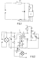
- a and B are input terminals for connecting to an AC voltage network of e.g. 220 V, 50 Hz.
- a high-pressure gas discharge lamp 2 is connected in series with a high-frequency oscillator 3 to these input terminals via a current limiter 1.
- the outputs of the RF oscillator 3 are labeled C and D.
- the current limiter 1 can be an ohmic resistor, a choke coil or an electronic ballast.
- a high-frequency snap-back capacitor 4 In parallel with the lamp 2 and the RF oscillator 3 is a high-frequency snap-back capacitor 4, which prevents high-frequency currents from being fed back into the AC voltage network.
- the RF oscillator 3 In addition to the 50 Hz mains alternating lamp current, the RF oscillator 3 also couples a small high-frequency current into the lamp 2 with a frequency between 50 kHz and 1 MHz. Typically, the RF oscillator 3 would operate throughout the AC period. In order to reduce the circuit losses, the HF oscillator 3 should only oscillate in the vicinity of the zero crossings of the AC lamp current.
- a current sensor 15 e.g. in the form of an alternating current converter, which measures the lamp current and passes it on to input terminals E and F of the RF oscillator 3.
- Another input G of the RF oscillator 3 is connected to the electrode of the lamp 2 which is not connected to the output C of the RF oscillator 3.
- FIG. 2 An embodiment of a suitable RF oscillator 3, which works on the principle of the flyback converter, is shown in FIG. 2.
- a bridge rectifier 5 with four diodes is connected to the input terminals A ⁇ , B 'of the AC voltage network, the output of which is connected to a charging capacitor 6 in parallel.
- the rectifier arrangement 5, 6 forms a DC voltage source for the actual HF oscillator 3.
- This essentially consists. from a high-frequency transformer 7 with a primary winding 8 and two secondary windings 9 and 10 and a transistor 11 lying in series with the primary winding 8, which can be switched on and off periodically.
- the HF transformer 7 with its primary winding 8 is in series with the transistor 11 and a Resistor 12 to the drawer capacitor 6 connected.
- the first secondary winding 9 of the HF transformer 7 is in series with the lamp 2.
- a voltage divider with its resistors 13 and 14 is also connected in parallel with the charging capacitor 6.
- the voltage divider tap between the two resistors 13 and 14 is connected to one end of the second secondary winding 10 of the HF transformer 7, the other end of which is connected to the base of the transistor 11.
- the ratio between the on and off time (duty cycle) of the transistor 11 is determined by reducing the ratio of the voltage dividing resistors 14 to 13, i.e. by reducing the divided DC voltage to supply the RF oscillator 3, and / or by increasing the number of turns of the second secondary winding 10 so small that the effective value of the high frequency current coupled into the lamp 2 is between 0.05 and 5% of the AC lamp current.
- the duty cycle of the transistor 11, once set, also determines the oscillation frequency of the RF oscillator 3.
- the base-emitter path of the switching transistor 11 is bridged by a further transistor 16 in series with a resistor 17.
- the signal applied by the current sensor 15 to the input terminals E and F of the RF oscillator 3 is rectified by a bridge rectifier 18 and fed to the base of the second transistor 16 via a potentiometer 19.
- the size of the base voltage can be adjusted using the potentiometer 19.
- the transistor 16 becomes conductive, so that the resistor 14, the smaller resistor 17 is connected in parallel.
- the base voltage of the transistor 11 is lowered to such an extent that it remains in the non-conductive state and the RF oscillator 3 cannot oscillate.
- the threshold value of the lamp current, from which oscillation is prevented, can be set via the potentiometer 19.
- the lamp voltage present at the input G of the RF oscillator 3 is applied to a smoothing capacitor 23 via a voltage divider consisting of resistors 20 and 21 and a diode 22.
- the time constant of the resistor 20 and the smoothing capacitor 23 is designed such that a voltage is present at the smoothing capacitor 23 which is proportional to the mean lamp voltage.
- the voltage across the smoothing capacitor 23 is then applied to the base of the further transistor 16 via a second diode 24.
- the voltage taken from the potentiometer 19 is applied to the base of the further transistor 16 via a third diode 25.
- the two diodes 24 and 25 prevent mutual interference between the current-proportional signal from the potentiometer 19 and the voltage-proportional signal from the smoothing capacitor 23.
- the RF oscillator 3 is switched off both outside the vicinity of the zero crossings of the lamp alternating current by the one tapped by the potentiometer 19 Voltage turns the further transistor 16 on, and also when a predetermined mean lamp voltage is exceeded, in that the voltage taken from the smoothing capacitor 23 turns the further transistor 16 on.
- the switching threshold for the lamp lamp voltage is set via the voltage divider 20, 21 so that the RF oscillator 3 is only switched off after the lamp 2 has warmed up, ie at a voltage which corresponds approximately to the normal lamp lamp voltage.
- the oscillation frequency of the HF oscillator was about 200 kHz with a peak voltage of about 200 V.
- the metal halide discharge lamps went through their warm-up phase without reignition problems.
- the AC lamp current was approximately 0.6 A and the effective value of the high-frequency current was approximately 0.5 mA.
- the lamp is connected in series with the RF oscillator.
Landscapes
- Circuit Arrangements For Discharge Lamps (AREA)
Priority Applications (1)
| Application Number | Priority Date | Filing Date | Title |
|---|---|---|---|
| AT85200313T ATE40253T1 (de) | 1984-03-08 | 1985-03-04 | Schaltungsanordnung zum wechselstrombetrieb von hochdruckgasentladungslampen. |
Applications Claiming Priority (2)
| Application Number | Priority Date | Filing Date | Title |
|---|---|---|---|
| DE3408426 | 1984-03-08 | ||
| DE19843408426 DE3408426A1 (de) | 1984-03-08 | 1984-03-08 | Schaltungsanordnung zum wechselstrombetrieb von hochdruck-gasentladungslampen |
Publications (2)
| Publication Number | Publication Date |
|---|---|
| EP0155729A1 true EP0155729A1 (fr) | 1985-09-25 |
| EP0155729B1 EP0155729B1 (fr) | 1989-01-18 |
Family
ID=6229857
Family Applications (1)
| Application Number | Title | Priority Date | Filing Date |
|---|---|---|---|
| EP85200313A Expired EP0155729B1 (fr) | 1984-03-08 | 1985-03-04 | Circuit pour l'exploitation à courant alternatif pour lampes à décharge à haute pression |
Country Status (6)
| Country | Link |
|---|---|
| US (1) | US5025197A (fr) |
| EP (1) | EP0155729B1 (fr) |
| JP (1) | JPS60207295A (fr) |
| AT (1) | ATE40253T1 (fr) |
| CA (1) | CA1256936A (fr) |
| DE (2) | DE3408426A1 (fr) |
Cited By (2)
| Publication number | Priority date | Publication date | Assignee | Title |
|---|---|---|---|---|
| EP1784062A1 (fr) * | 2005-05-10 | 2007-05-09 | Patent-Treuhand-Gesellschaft für elektrische Glühlampen mbH | Ballast électronique et procédure de réglage |
| WO2007122114A1 (fr) * | 2006-04-20 | 2007-11-01 | Patent-Treuhand-Gesellschaft für elektrische Glühlampen mbH | Agencement et procédé de commande d'une lampe à décharge à haute pression |
Families Citing this family (3)
| Publication number | Priority date | Publication date | Assignee | Title |
|---|---|---|---|---|
| US5412222A (en) * | 1993-06-30 | 1995-05-02 | Eastman Kodak Company | Storage phosphor reader having erase lamp feature failure detection |
| US5610477A (en) * | 1994-04-26 | 1997-03-11 | Mra Technology Group | Low breakdown voltage gas discharge device and methods of manufacture and operation |
| KR100406898B1 (ko) * | 1995-10-20 | 2004-05-20 | 가부시키 가이샤 히다치 카 엔지니어링 | 차량용내연기관의제어방법및장치 |
Citations (4)
| Publication number | Priority date | Publication date | Assignee | Title |
|---|---|---|---|---|
| GB1092199A (en) * | 1964-07-28 | 1967-11-22 | Philips Electronic Associated | Improvements in and relating to circuits for the current supply to gas and/or vapour discharge lamps |
| GB2098416A (en) * | 1981-05-08 | 1982-11-17 | Egyesuelt Izzolampa | Ballast circuits for discharge lamps |
| US4378514A (en) * | 1980-10-27 | 1983-03-29 | General Electric Company | Starting and operating circuit for gaseous discharge lamps |
| GB2106729A (en) * | 1981-09-11 | 1983-04-13 | Philips Nv | Electric arrangement for operating a gas and/or vapour discharge lamp |
Family Cites Families (5)
| Publication number | Priority date | Publication date | Assignee | Title |
|---|---|---|---|---|
| US3411108A (en) * | 1967-02-02 | 1968-11-12 | Motorola Inc | Starting circuits for magnetic core voltage inverter systems |
| US4087722A (en) * | 1975-05-01 | 1978-05-02 | American Ionetics, Inc. | Apparatus and method for supplying power to gas discharge lamp systems |
| DE2961104D1 (en) * | 1978-02-11 | 1981-12-10 | Elstrom Control System Ag | Electronic device for controlling the light intensity of a gaseous discharge lamp without a heated cathode |
| US4392081A (en) * | 1981-07-31 | 1983-07-05 | General Electric Company | Lighting unit |
| US4464607A (en) * | 1981-09-25 | 1984-08-07 | General Electric Company | Lighting unit |
-
1984
- 1984-03-08 DE DE19843408426 patent/DE3408426A1/de not_active Withdrawn
-
1985
- 1985-03-04 DE DE8585200313T patent/DE3567787D1/de not_active Expired
- 1985-03-04 AT AT85200313T patent/ATE40253T1/de not_active IP Right Cessation
- 1985-03-04 EP EP85200313A patent/EP0155729B1/fr not_active Expired
- 1985-03-05 US US06/708,316 patent/US5025197A/en not_active Expired - Fee Related
- 1985-03-06 JP JP60042753A patent/JPS60207295A/ja active Pending
- 1985-03-07 CA CA000476000A patent/CA1256936A/fr not_active Expired
Patent Citations (4)
| Publication number | Priority date | Publication date | Assignee | Title |
|---|---|---|---|---|
| GB1092199A (en) * | 1964-07-28 | 1967-11-22 | Philips Electronic Associated | Improvements in and relating to circuits for the current supply to gas and/or vapour discharge lamps |
| US4378514A (en) * | 1980-10-27 | 1983-03-29 | General Electric Company | Starting and operating circuit for gaseous discharge lamps |
| GB2098416A (en) * | 1981-05-08 | 1982-11-17 | Egyesuelt Izzolampa | Ballast circuits for discharge lamps |
| GB2106729A (en) * | 1981-09-11 | 1983-04-13 | Philips Nv | Electric arrangement for operating a gas and/or vapour discharge lamp |
Cited By (2)
| Publication number | Priority date | Publication date | Assignee | Title |
|---|---|---|---|---|
| EP1784062A1 (fr) * | 2005-05-10 | 2007-05-09 | Patent-Treuhand-Gesellschaft für elektrische Glühlampen mbH | Ballast électronique et procédure de réglage |
| WO2007122114A1 (fr) * | 2006-04-20 | 2007-11-01 | Patent-Treuhand-Gesellschaft für elektrische Glühlampen mbH | Agencement et procédé de commande d'une lampe à décharge à haute pression |
Also Published As
| Publication number | Publication date |
|---|---|
| EP0155729B1 (fr) | 1989-01-18 |
| US5025197A (en) | 1991-06-18 |
| DE3408426A1 (de) | 1985-09-12 |
| CA1256936A (fr) | 1989-07-04 |
| ATE40253T1 (de) | 1989-02-15 |
| JPS60207295A (ja) | 1985-10-18 |
| DE3567787D1 (en) | 1989-02-23 |
Similar Documents
| Publication | Publication Date | Title |
|---|---|---|
| DE69019648T2 (de) | Gerät zur Versorgung einer Leuchtstofflampe. | |
| DE2640780C2 (fr) | ||
| DE3903520C2 (fr) | ||
| EP0113451B1 (fr) | Inverseur avec un circuit de charge comprenant un circuit à résonance série et une lampe à décharge | |
| EP0763276B1 (fr) | Alimentation electrique a decoupage destinee au fonctionnement de lampes electriques | |
| DE3407067C2 (de) | Steuerschaltung für Gasentladungslampen | |
| EP0800335B1 (fr) | Circuit pour alimenter des lampes électriques | |
| DE2705969A1 (de) | Vorschaltanordnung fuer entladungslampe | |
| DE2705968A1 (de) | Starter- und vorschaltanordnung fuer gasentladungslampe | |
| DE19548506A1 (de) | Schaltungsanordnung zum Betrieb einer Lampe | |
| DE3611611A1 (de) | Schaltungsanordnung zum hochfrequenten betrieb einer niederdruckentladungslampe | |
| CH657003A5 (de) | Vorschaltanordnung zum betreiben von mindestens einer niederdruckentladungslampe. | |
| DE69616479T2 (de) | Schaltungsanordnung | |
| DE2948287A1 (de) | Schaltungsanordnung fuer hochintensitaetsentladungslampen | |
| DE69610049T2 (de) | Schaltungsanordnung zum zünden einer hochdruckgasentladungslampe | |
| DE69202783T2 (de) | Zünd- und Betriebsschaltung für Bogenentladungslampe. | |
| DE2835044A1 (de) | Lastschaltung fuer leuchtstofflampen | |
| DE69835328T2 (de) | Steuerschaltung für eine Fluroreszenzlampe | |
| EP0541909B1 (fr) | Circuit pour alimenter des lampes à décharge | |
| DE69017940T2 (de) | Wechselrichter zum Speisen zweier Gas und / oder Dampfentladungslampen. | |
| EP0057910B1 (fr) | Circuit pour l'alimentation régulée d'un utilisateur | |
| AT397326B (de) | Schaltungsanordnung für die zündung und den betrieb von gasentladungslampen | |
| EP0155729B1 (fr) | Circuit pour l'exploitation à courant alternatif pour lampes à décharge à haute pression | |
| DE69709604T2 (de) | Schaltungsanordnung | |
| DE69109333T2 (de) | Schaltanordnung. |
Legal Events
| Date | Code | Title | Description |
|---|---|---|---|
| PUAI | Public reference made under article 153(3) epc to a published international application that has entered the european phase |
Free format text: ORIGINAL CODE: 0009012 |
|
| AK | Designated contracting states |
Designated state(s): AT DE FR GB NL |
|
| 17P | Request for examination filed |
Effective date: 19860305 |
|
| RAP1 | Party data changed (applicant data changed or rights of an application transferred) |
Owner name: N.V. PHILIPS' GLOEILAMPENFABRIEKEN Owner name: PHILIPS PATENTVERWALTUNG GMBH |
|
| 17Q | First examination report despatched |
Effective date: 19880408 |
|
| GRAA | (expected) grant |
Free format text: ORIGINAL CODE: 0009210 |
|
| AK | Designated contracting states |
Kind code of ref document: B1 Designated state(s): AT DE FR GB NL |
|
| REF | Corresponds to: |
Ref document number: 40253 Country of ref document: AT Date of ref document: 19890215 Kind code of ref document: T |
|
| REF | Corresponds to: |
Ref document number: 3567787 Country of ref document: DE Date of ref document: 19890223 |
|
| GBT | Gb: translation of ep patent filed (gb section 77(6)(a)/1977) | ||
| ET | Fr: translation filed | ||
| PLBE | No opposition filed within time limit |
Free format text: ORIGINAL CODE: 0009261 |
|
| STAA | Information on the status of an ep patent application or granted ep patent |
Free format text: STATUS: NO OPPOSITION FILED WITHIN TIME LIMIT |
|
| 26N | No opposition filed | ||
| PGFP | Annual fee paid to national office [announced via postgrant information from national office to epo] |
Ref country code: FR Payment date: 19900320 Year of fee payment: 6 Ref country code: AT Payment date: 19900320 Year of fee payment: 6 |
|
| PGFP | Annual fee paid to national office [announced via postgrant information from national office to epo] |
Ref country code: NL Payment date: 19900331 Year of fee payment: 6 |
|
| PGFP | Annual fee paid to national office [announced via postgrant information from national office to epo] |
Ref country code: DE Payment date: 19900523 Year of fee payment: 6 |
|
| PGFP | Annual fee paid to national office [announced via postgrant information from national office to epo] |
Ref country code: GB Payment date: 19910301 Year of fee payment: 7 |
|
| PG25 | Lapsed in a contracting state [announced via postgrant information from national office to epo] |
Ref country code: AT Effective date: 19910304 |
|
| PG25 | Lapsed in a contracting state [announced via postgrant information from national office to epo] |
Ref country code: NL Effective date: 19911001 |
|
| NLV4 | Nl: lapsed or anulled due to non-payment of the annual fee | ||
| PG25 | Lapsed in a contracting state [announced via postgrant information from national office to epo] |
Ref country code: FR Effective date: 19911129 |
|
| PG25 | Lapsed in a contracting state [announced via postgrant information from national office to epo] |
Ref country code: DE Effective date: 19920101 |
|
| REG | Reference to a national code |
Ref country code: FR Ref legal event code: ST |
|
| PG25 | Lapsed in a contracting state [announced via postgrant information from national office to epo] |
Ref country code: GB Effective date: 19920304 |
|
| GBPC | Gb: european patent ceased through non-payment of renewal fee |