EP0155748A2 - Méthode de régulation d'un moteur à combustion interne - Google Patents
Méthode de régulation d'un moteur à combustion interne Download PDFInfo
- Publication number
- EP0155748A2 EP0155748A2 EP85300361A EP85300361A EP0155748A2 EP 0155748 A2 EP0155748 A2 EP 0155748A2 EP 85300361 A EP85300361 A EP 85300361A EP 85300361 A EP85300361 A EP 85300361A EP 0155748 A2 EP0155748 A2 EP 0155748A2
- Authority
- EP
- European Patent Office
- Prior art keywords
- engine speed
- electrical load
- generator
- generating state
- speed
- Prior art date
- Legal status (The legal status is an assumption and is not a legal conclusion. Google has not performed a legal analysis and makes no representation as to the accuracy of the status listed.)
- Granted
Links
- 238000000034 method Methods 0.000 title claims abstract description 33
- 238000002485 combustion reaction Methods 0.000 title claims abstract description 14
- 239000000446 fuel Substances 0.000 description 17
- 230000008859 change Effects 0.000 description 15
- 238000002347 injection Methods 0.000 description 9
- 239000007924 injection Substances 0.000 description 9
- 230000008569 process Effects 0.000 description 8
- 230000001133 acceleration Effects 0.000 description 6
- 239000002826 coolant Substances 0.000 description 4
- 230000003247 decreasing effect Effects 0.000 description 4
- 230000004048 modification Effects 0.000 description 4
- 238000012986 modification Methods 0.000 description 4
- 238000010586 diagram Methods 0.000 description 3
- 230000000694 effects Effects 0.000 description 3
- 239000000203 mixture Substances 0.000 description 3
- 238000001816 cooling Methods 0.000 description 2
- 230000006870 function Effects 0.000 description 2
- 101001064674 Homo sapiens tRNA pseudouridine(38/39) synthase Proteins 0.000 description 1
- 230000008901 benefit Effects 0.000 description 1
- 230000004044 response Effects 0.000 description 1
- 238000007493 shaping process Methods 0.000 description 1
- 102100031917 tRNA pseudouridine(38/39) synthase Human genes 0.000 description 1
Images

Classifications
-
- F—MECHANICAL ENGINEERING; LIGHTING; HEATING; WEAPONS; BLASTING
- F02—COMBUSTION ENGINES; HOT-GAS OR COMBUSTION-PRODUCT ENGINE PLANTS
- F02D—CONTROLLING COMBUSTION ENGINES
- F02D31/00—Use of speed-sensing governors to control combustion engines, not otherwise provided for
- F02D31/001—Electric control of rotation speed
- F02D31/002—Electric control of rotation speed controlling air supply
- F02D31/003—Electric control of rotation speed controlling air supply for idle speed control
- F02D31/005—Electric control of rotation speed controlling air supply for idle speed control by controlling a throttle by-pass
-
- F—MECHANICAL ENGINEERING; LIGHTING; HEATING; WEAPONS; BLASTING
- F02—COMBUSTION ENGINES; HOT-GAS OR COMBUSTION-PRODUCT ENGINE PLANTS
- F02D—CONTROLLING COMBUSTION ENGINES
- F02D41/00—Electrical control of supply of combustible mixture or its constituents
- F02D41/02—Circuit arrangements for generating control signals
- F02D41/04—Introducing corrections for particular operating conditions
- F02D41/08—Introducing corrections for particular operating conditions for idling
- F02D41/083—Introducing corrections for particular operating conditions for idling taking into account engine load variation, e.g. air-conditionning
Definitions
- the present invention relates to a method of feedback-controlling the idling speed of an internal combustion engine and, more particularly, to an idling speed feedback control method wherein the magnitude of the electrical load on the engine, when electrical load equipment or devices are in an operative state is accurately detected, and supplementary air is applied in accordance with the magnitude of electrical load, to thereby eliminate any speed control delay.
- An idling speed feedback control method in which a target idling speed is set in accordance with the load conditions of an engine, and the difference between the target idling speed and the actual engine speed is detected. The engine is then supplied with an amount of auxiliary air which corresponds to the magnitude of the detected difference so that the difference becomes zero, thereby controlling the engine speed so that it is maintained at the target idling speed, e.g., Japanese Patent Laid-Open No. 98,628/80.
- an electrical load device such as a headlight or an electrically-operated radiator cooling fan motor
- feedback mode control idling speed feedback control
- an alternating current (AC) generator which supplies electric power to the actuated electrical load
- the operation of the AC generator increases the engine load, resulting in a lowering of the engine speed.
- the lowered engine speed is shortly returned to the target idling speed by virtue of the feedback mode control.
- the engine may be stalled, or it may become impossible to smoothly engage the clutch when the vehicle is started simultaneously with increasing of the electrical load.
- an engine speed control method has been proposed by the applicant of the present invention in Japanese Application Laid-Open No. 197,449/83, in which the ON-OFF state of each of a plurality of electrical load devices is detected, and at the same time, as the ON state of each electrical load device is detected, the valve-opening duration of a control valve which controls the auxiliary air amount is increased by a predetermined period of time in accordance with the magnitude of the electrical load, whereby the delay in the auxiliary air amount control is minimized, thereby improving driveabflity.
- a method may be adopted in which, only some of the electrical equipment, for example, some of the which apply a heavy load to the engine are monitored for the purpose of control, and the electrical load correction of the auxiliary air amount is effected only when one of the monitored electrical devices is turned ON or OFF.
- the electrical load correction of the auxiliary air amount is effected only when one of the monitored electrical devices is turned ON or OFF.
- the present invention aims at overcoming the above-described problems and provides an idling speed feedback control method wherein, during the idling operation of an internal combustion engine which has electrical load equipment and a generator supplying electric power to the electrical load equipment and which drives the generator, feedback control is effected on the basis of a control signal which is determined in accordance with the difference between actual engine speed and a target idling speed.
- the method of feedback-controlling the idling speed of the internal combustion engine comprises the steps of: detecting a generating state signal value representing the generating state of the generator; detecting an actual engine speed signal; determining an electrical load correction value in accordance with the detected generating state signal value and the detected actual engine speed signal; and correcting the control amount during the idling operation in accordance with the determined electrical load correction value.
- the magnitude of all the electrical loads in an operative state is accurately detected from the generating state of the generator which supplies electric power to the electric load devices, thereby eliminating any idle speed feedback control delay of the internal combustion engine.
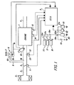
- Fig. 1 schematically shows an engine speed controller for an internal combustion engine to which the method of the present invention is applied.
- a four-cylinder internal combustion engine 1 is connected to an intake pipe 3 having an air cleaner 2 mounted at its forward end and an exhaust pipe 4 connected to its rear end.
- a throttle valve 5 is disposed in the intake pipe 3.
- an air passage 8 is provided which has one end 8a opening into a portion of the intake pipe 3 on the downstream side of the throttle valve 5 and the other end communicating with the atmosphere through an air cleaner 7.
- An auxiliary air amount control valve 6 (referred to simply as a “control valve”, hereinafter) is disposed in an intermediate portion of the air passage 8. The control valve 6 controls the amount of auxiliary air to be supplied to the engine 1.
- the control valve 6 comprises a normally-closed type electromagnetic valve which has a solenoid 6a and a valve 6b wliich opens the air passage 8 when the solenoid 6a is energized.
- the solenoid 6a is electrically connected to an electronic control unit 9 (referred to as an "ECU”, hereinafter).
- a fuel injection valve 10 projects into the intake pipe 3 at a location between the engine 1 and the opening 8a of the air passage 8.
- the fuel injection valve 10 is connected to a fuel pump, not shown, and also is electrically connected to the ECU 9.
- a throttle valve opening sensor 11 is attached to the throttle valve 5.
- An intake manifold absolute pressure sensor 13 which communicates with the intake pipe 3 through a pipe 12 is provided in the intake pipe 3 on the downstream side of the opening 8a of the air passage 8.
- an engine coolant temperature sensor 14 and an engine rpm sensor 15 are attached to the body of the engine 1. These sensors are electrically connected to the ECU 9.
- a battery 19, an alternating current (AC) generator 20, and a voltage regulator 21 which supplies field coil current to the generator 20 are connected in parallel between node 19a and ground and supply power to load equipment 16, 17 and 18.
- a field coil current output terminal 21a of the voltage regulator 21 is connected to a field coil current input terminal 20a of the generator 20 through a generating state detector 22.
- the generating state detector 22 supplies the ECU 9 with a signal representing the generating state of the generator 20, for example, a signal E having a voltage level corresponding to the magnitude of the field coil current supplied from the voltage regulator 21 to the generator 20.
- the generator 20 is mechanically connected to an output shaft (not shown) of the engine 1 and is driven by the engine 1.
- the switches 16a, 17a, 18a are closed (ON)
- electric power is supplied to the electrical load equipment 16, 17 and 18 from the generator 20.
- the electric power required for operating the electrical load equipment 16, 17 and 18 exceeds the generating capacity of the generator 20, a shortage of the electric power is complemented by the battery 19.
- the ECU 9 determines engine operating conditions and engine load conditions, such as electrical load conditions, and sets a target idling speed during an idling operation in accordance with these determined conditions.
- the ECU 9 further calculates the amount of fuel to be supplied to the engine 1, that is, a valve-opening duration for the fuel injection valve 10, and also the amount of auxiliary air to be supplied to the engine 1, that is, a valve-opening duty ratio of the control valve 6.
- the ECU supplies the respective driving signals to the fuel injection valve 10 and the control valve 6 in accordance with the respective calculated values.
- the solenoid 6a of the control valve 6 is energized over a valve-opening duration corresponding to the calculated valve-opening duty ratio, to open the valve 6b thereby opening the air passage 8, whereby a necessary amount of auxiliary air corresponding to the calculated valve-opening duration is supplied to the engine 1 through the air passage 8 and the intake pipe 3.
- the fuel injection valve 10 is opened over a valve-opening duration corresponding to the above-described calculated value to inject fuel into the intake pipe 3.
- the ECU 9 operates to supply an air/fuel mixture having a desired air/fuel ratio, e.g. a stoichimetric air/fuel ratio, to the engine 1. 0
- valve-opening duration of the control valve 6 When the valve-opening duration of the control valve 6 is increased to increase the amount of auxiliary air, the increased amount of the air-fuel mixture is supplied to the engine 1 to thereby increase the engine output resulting in a rise in the engine speed. Conversely, when the valve-opening duration of the control valve 6 is decreased, the amount of a air/fuel mixture supplied is decreased, resulting in a decrease in the engine speed. Thus, it is possible to control the engine speed by controlling the amount of auxiliary air, that is, the valve-opening duration of the control valve 6.
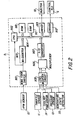
- Fig. 2 shows a circuit diagram of the ECU 9 shown in Fig. 1.
- An output signal from the engine rpm sensor 15 is applied to a waveform shaping circuit 901 an is then supplied to a central processing unit (CPU) 902 and also to an M e counter 903 as a TDC signal representing a predetermined angle of the crank angle, for example, the top dead center.
- the M e counter 903 counts the interval of time from the preceding pulse of a TDC signal to the present pulse of a TDC signal, and therefore the count M is inversely proportional to the engine speed N e .
- the M e counter 903 supplies the counted value M to the CPU 902 via a data bus 904.
- Output signals from various sensors such as the throttle valve opening sensor 11, the intake manifold pressure sensor 13 and the engine coolant temperature sensor 14, which are shown in Fig. 1, together with a signal from the generating state detector 22, are modified to a predetermined voltage level in a level shifter unit 905 and are then successively applied to an A/D converter 907 by means of a multiplexer 906.
- the A/D converter 907 successively converts the signals from the sensors 11, 13, 14 and the detector 22 into digital signals and supplies the digital signals to the CPU 902 via the data bus 904.
- the CPU 902 is further connected via the data bus 904 to a read only memory (ROM) 910, a random-access memory (RAM) 911 and driving circuits 912, 913.
- the RAM 911 temporarily stores, for example, the results of the calculation carried out in the CPU 902 and various sensor outputs.
- the ROM 910 stores a control program executed in the CPU 902 and a valve-opening duty ratio D EX table as a reference correction value, described later.
- the CPU 902 executes the control program stored in the ROM 910, evaluates engine operating conditions and engine load conditions on the basis of the above-described various engine parameters and generating state signal, and calculates a valve-opening duty ratio D OUT for the control valve 6 which controls the amount of auxiliary air.
- the CPU 902 then supplies the driving circuit 912 with a control signal corresponding to the calculated value.
- the CPU 902 further calculates a fuel injection duration TOUT for the fuel injection valve 10 and supplies a control signal based on the calculated value to the driving circuit 913 via the data bus 904.
- the driving circuit 913 supplies the fuel injection valve 10 with a control signal, which opens the fuel injection valve 10, in accordance with the calculated value.
- the driving circuit 912 supplies the control valve 6 with an ON-OFF driving signal which controls the control valve 6.
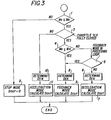
- Fig. 3 is a program flow chart showing the calculation of the valve-opening duty ratio D OUT of the control valve 6 which is executed in the CPU 902 each time a TDC signal pulse is generated.
- the counting is effected by the M e counter 903 in the ECU 9, and a decision is made as to whether or not a value M e which is proportional to the reciprocal of the engine speed N e is larger than a value M A corresponding to the reciprocal of a predetermined engine speed N A (e.g., 1,500 rpm) (step 1).
- a value M e which is proportional to the reciprocal of the engine speed N e is larger than a value M A corresponding to the reciprocal of a predetermined engine speed N A (e.g., 1,500 rpm) (step 1).
- step 1 If the result of the decision in step 1 is negative (No) (Me MA is not valid), that is, if the engine speed N e is higher than the predetermined value N A , the supply of auxiliary air is not required, and consequently, the valve-opening duty ratio D OUT of the control valve 6 is set at zero in step 2, (the control mode in which the valve-opening duty ratio D OUT is set at zero so that the control valve 6 is totally closed will be referred to as a "stop mode", hereinafter).
- step 1 If the result of the decision in step 1 is affirmative (Yes) (M e > M A is valid), that is, if the engine speed N e is lower than the predetermined value N A , a decision is made as to whether or not the throttle valve 5 is substantially fully closed in step 3. If the throttle valve 5 5 is substantially fully closed, then, a decision is made as to whether or not M e2 is larger than a value M H corresponding to the reciprocal of a predetermined higher-limit value N H of the target idling speed in step 4.
- step 5 If the result of the decision is negative (No), that is, if the engine speed N e is higher than the predetermined higher-limit value N H of the target idling speed, and if the preceding control loop was not effected by a feedback mode as described later (the result of a decision in a step 5 is negative (No)), an electrical load term D En corresponding to the engine speed N e and the value of a generating state signal from the generating state detector 22 shown in Fig. 1 is calculated in step 6, as described later in detail. Then, the process proceeds to step 7, in which the valve-opening duty ratio D OUT in the control of a deceleration mode is calculated.
- the duty ratio D OUT for deceleration mode control is set, for instance, to a value which is the sum of a deceleration mode term Dx and an electrical load term D En calculated in the step 6.
- the deceleration mode term Dx may be set at a predetermined value corresponding to the values of engine operating condition parameter signals, such as a signal from the engine coolant temperature sensor, for maintaining the engine speed N e at desired idling rpm.
- the engine has previously been supplied with an amount of auxiliary air set by the deceleration mode over the period from when the engine speed N e becomes lower than the predetermined speed N A to the time when the engine speed N e reaches the higher-limit value N H of the target idling speed and the control by the feedback mode, described later, is commenced. It is thus possible to smoothly shift to the control of the feedback mode control without any possibility of the engine speed undershooting the target idling speed.
- step 8 If the engine speed N e is lowered such that the result of the decision in the step 4 is affirmative (Yes) (M e ⁇ M H is valid), that is, if the engine speed N e becomes lower than the predetermined higher-limit value N H of the target idling speed, calculation of the electrical load term D En is carried out as described later (step 8), and then, calculation of the valve-opening duty ratio D OUT in the control by the feedback mode is carried out in step 9.
- the calculation of the valve-opening duty ratio D OUT by the feedback mode is carried out such that, for example, a value of a valve-opening duty ratio for the present loop is obtained by adding the electrical load term D En calculated in step 8 to a PI control term D PIn calculated in accordance with the difference between the target idling speed and the actual engine speed to make difference zero, that is, to make the engine speed N e equal to the predetermined higher and lower limit values N H and N L of the target idling speed.
- the auxiliary air amount control by the feedback mode is continued even if the engine speed N exceeds the higher-limit value N H , as long as the throttle valve 5 is fully closed. This is because there is no fear of any engine stall and it is possible to effect a speedy and accurate speed control.
- step 4 When the engine speed exceeds the higher-limit value NH of the target idling speed due to a change or cutting off of electrical loads, the fact that M e ⁇ M H is not valid is decided in step 4, and the process proceeds to step 5, in which a decision is made as to whether or not the preceding control loop was effected by the feedback mode. If it was the feedback mode (if the result of the decision is affirmative (Yes)), the process proceeds to steps 8 and 9, in which control by the feedback mode is continued.
- step 3 when the throttle valve 5 is opened during the idling operation by the feedback mode control, an auxiliary air amount control of an acceleration mode is commenced. More specifically, if the result of the decision in step 3 is negative (No), the process proceeds to step 10, in which the electrical load term D En' described later, is calculated, and then, in step 11, calculation of the valve-opening duty ratio in the control of the acceleration mode is carried out.
- the calculation of the valve-opening duty ratio D OUT in the acceleration mode is carried out as follows: When the throttle valve 5 is opened during the idling operation such that the engine operation is shifted to an acceleration operation, the supply of auxiliary air by the control valve 6 is not abruptly suspended, but the valve-opening duty ratio set in the feedback mode control immediately prior to opening of the throttle valve 5 is used as an initial value D PIn-1 . Thereafter, the initial value is decreased by a predetermined value A D Acc every time a TDC signal pulse is generated until the initial value becomes zero, and the electrical load term D En calculated in step 10 is added to the thus decreased valve-opening duty ratio value (D PIn-1 - A D Acc ), thereby setting the valve-opening duty ratio D OUT for the present loop.
- D PIn-1 a predetermined value
- D Acc the electrical load term
- Fig. 4 is a flow chart showing the calculation of the electrical load term D En executed in steps 6, 8 and 10 of Fig. 3.
- the value E of a generating state signal is read out from the generating state detector 22 shown in Fig. 1, the value of E corresponding to the magnitude of the field coil current of the generator 20 (step 1), and E is converted into a digital signal in the A/D converter 907.
- a D En value is set from a correction coefficient K E and a table showing the relationship between the valve-opening duty ratio D EX and the generating state signal value E (step 2).
- a valve-opening duty ratio D EX corresponding to the generating state signal value E is determined from, for example, a table showing the relationship between the valve-opening duty ratio D EX and the generating state signal value E at a reference engine speed (e.g., 700 rpm) such as that shown in Fig. 5.
- a reference engine speed e.g. 700 rpm
- generating state signal values are respectively set at E l (e.g., 1 V), E 2 (e.g., 2 V), E 3 (e.g., 3 V) and E 4 (e.g., 4.5 V), and valve-opening duty ratios as reference correction values corresponding to the set values are respectively set at DE1 (e .g., 50%), D E2 (e .g., 30%), D E3 (e .g., 10%), and D E4 (e.g., 0%).
- DE1 e.g. 50%
- D E2 e.g., 30%
- D E3 e.g., 10%
- D E4 e.g., 0%
- the correction coefficient K E is a value calculated in accordance with the difference between a value M ec corresponding to the reciprocal of the reference engine speed (700 rpm) and a value M e counted by the M counter 903 shown in Fig. 2, according to the following formula (2): where represents a constant (e.g., 8 x 10 -4 ).
- the reason the electrical load term D En is set as a function of the engine speed N e and the value E of the generating state signal corresponding to the field coil current of the generator is that the magnitude of the loads on the engine when the generator is in an operative state is proportional to the amount of electric power generated by the generator and the amount of generated electric power is a function of the magnitude of the field coil current and the engine speed, that is, the number of revolutions of the rotor of the generator.
- step 5 or 6 If the result of the decision in step 5 or 6 is affirmative (Yes), that is, if the change amount A D E is larger than the first predetermined value ⁇ D EG1 in step 5, or if the absolute value
- of the change amount is larger than the second predetermined value ⁇ D EG2 in step 6, it means that there has been a change in the ON-OFF state of an electrical load device which imposes a relatively heavy load on the engine. In this case, it is predicted that the engine speed will suddenly increase or decrease. In order to avoid any delay in controlling the auxiliary air amount in response to such a sudden increase or decrease of the engine speed, the process proceeds to step 8, in which the value of the electrical load term D En set in step 2 is used as the D En value for the present loop (step 8).
- step 5 If the result of the decision in step 5 is negative (No), that is, if the change amount ⁇ DE is positive and smaller than the first predetermined value ⁇ DEG1, it is predicted that the engine speed will not suddenly change. In such a case, stable speed control can be obtained by gradually increasing the electrical load term value of the valve-opening duty ratio DOUT toward the value D En set for the present loop. For this reason, the process proceeds to step 7, in which an electrical load term value D En for the present loop is obtained through the following formula (3):
- a represents a modification coefficient, which is set at, for example, the value 0.5 in accordance with dynamic characteristics of the engine. It is to be noted that, if the modification coefficient a is set at the value 1, since the formula (3) is given as follows: Thus, the formula (3) is coincident with the formula for calculation in step 8.
- step 6 the process proceeds to step 9, in which the electrical load term value D En for the present loop is obtained through the following formula (4):
- ⁇ represents a modification coefficient which is set separately from the above-described modification coefficient a and is set at, for example, the value 0.4 in accordance with the dynamic characteristics of the engine.
- the electrical load term D En is obtained in step 2 of Fig. 4 on the basis of the table showing the relationship between the valve-opening duty ratio D EX and the generating state signal value E and the formulas (1) and (2)
- this setting method is not exclusive.
- a setting method may be employed in which a plurality of electrical load term map values D En corresponding to the generating state signal value E and the engine speed Ne are previously stored in the ROM 910 and are read out in accordance with a detected generating state signal value E and an actual engine speed value N .
- the value of a signal representing the generating state of the generator is detected; an actual engine speed is detected; an electrical load correction value is determined which corresponds to the detected generating state signal value and the detected actual engine speed value; and the intake air amount during an idling operation is corrected by the determined electrical load correction value. Accordingly, it is possible to accurately detect engine load variations with a change in the ON-OFF state of each of the electrical load devices. Thus, it is possible to improve the speed control delay.
Landscapes
- Engineering & Computer Science (AREA)
- Chemical & Material Sciences (AREA)
- Combustion & Propulsion (AREA)
- Mechanical Engineering (AREA)
- General Engineering & Computer Science (AREA)
- Electrical Control Of Air Or Fuel Supplied To Internal-Combustion Engine (AREA)
Applications Claiming Priority (2)
| Application Number | Priority Date | Filing Date | Title |
|---|---|---|---|
| JP6773/84 | 1984-01-18 | ||
| JP59006773A JPS60150450A (ja) | 1984-01-18 | 1984-01-18 | 内燃エンジンのアイドル回転数フイ−ドバツク制御方法 |
Publications (3)
| Publication Number | Publication Date |
|---|---|
| EP0155748A2 true EP0155748A2 (fr) | 1985-09-25 |
| EP0155748A3 EP0155748A3 (en) | 1985-12-27 |
| EP0155748B1 EP0155748B1 (fr) | 1989-03-15 |
Family
ID=11647488
Family Applications (1)
| Application Number | Title | Priority Date | Filing Date |
|---|---|---|---|
| EP85300361A Expired EP0155748B1 (fr) | 1984-01-18 | 1985-01-18 | Méthode de régulation d'un moteur à combustion interne |
Country Status (4)
| Country | Link |
|---|---|
| US (1) | US4649878A (fr) |
| EP (1) | EP0155748B1 (fr) |
| JP (1) | JPS60150450A (fr) |
| DE (1) | DE3568825D1 (fr) |
Cited By (6)
| Publication number | Priority date | Publication date | Assignee | Title |
|---|---|---|---|---|
| EP0175162A3 (fr) * | 1984-09-19 | 1987-01-14 | Robert Bosch Gmbh | Dispositif électronique pour générer un signal de dosage de carburant pour un moteur à combustion |
| GB2217876A (en) * | 1988-04-22 | 1989-11-01 | Honda Motor Co Ltd | I/c engine control |
| EP0583184A1 (fr) * | 1992-08-12 | 1994-02-16 | Société Anonyme dite: REGIE NATIONALE DES USINES RENAULT | Procédé de régulation du régime ralenti d'un moteur à combustion interne |
| WO1995027847A1 (fr) * | 1994-04-12 | 1995-10-19 | United Technologies Corporation | Systeme de maintien automatique du regime d'un moteur |
| US5998881A (en) * | 1998-04-29 | 1999-12-07 | Chrysler Corporation | Apparatus and method for controlling low engine idle RPM without discharging a vehicle battery by monitoring the vehicle alternator field modulation |
| KR101236213B1 (ko) * | 2006-09-12 | 2013-02-22 | 소이텍 | 질화갈륨 기판을 형성하기 위한 프로세스 |
Families Citing this family (24)
| Publication number | Priority date | Publication date | Assignee | Title |
|---|---|---|---|---|
| JPS6210443A (ja) * | 1985-07-05 | 1987-01-19 | Honda Motor Co Ltd | 内燃エンジンのアイドル回転速度制御装置 |
| JPS6293452A (ja) * | 1985-10-21 | 1987-04-28 | Honda Motor Co Ltd | 内燃機関のアイドル回転数制御方法 |
| KR900001627B1 (ko) * | 1986-05-12 | 1990-03-17 | 미쓰비시전기 주식회사 | 내연기관의 아이들회전수 제어장치 |
| JPH07116960B2 (ja) * | 1987-09-08 | 1995-12-18 | 本田技研工業株式会社 | 内燃機関の作動制御装置 |
| US4881184A (en) * | 1987-09-08 | 1989-11-14 | Datac, Inc. | Turbine monitoring apparatus |
| US5271821A (en) * | 1988-03-03 | 1993-12-21 | Ngk Insulators, Ltd. | Oxygen sensor and method of producing the same |
| JPH01233140A (ja) * | 1988-03-14 | 1989-09-18 | Nissan Motor Co Ltd | 車両用窓ガラスの解氷装置 |
| JP2621084B2 (ja) * | 1988-08-02 | 1997-06-18 | 本田技研工業株式会社 | アイドル回転数制御装置 |
| KR900019335A (ko) * | 1989-05-09 | 1990-12-24 | 시끼 모리야 | 회전수 제어장치 |
| US5270575A (en) * | 1989-11-30 | 1993-12-14 | Mitsubishi Jidosha Kogyo Kabushiki Kaisha | Device for controlling change in idling |
| FR2691020B1 (fr) * | 1992-05-05 | 1994-08-05 | Valeo Equip Electr Moteur | Dispositif de regulation de la tension de sortie d'un alternateur, notamment dans un vehicule automobile. |
| US5402007A (en) * | 1993-11-04 | 1995-03-28 | General Motors Corporation | Method and apparatus for maintaining vehicle battery state-of-change |
| US5481176A (en) * | 1994-07-05 | 1996-01-02 | Ford Motor Company | Enhanced vehicle charging system |
| JP3592767B2 (ja) * | 1994-11-09 | 2004-11-24 | 三菱電機株式会社 | エンジンの制御装置 |
| JP3622529B2 (ja) * | 1998-09-11 | 2005-02-23 | トヨタ自動車株式会社 | 動力出力装置、およびそれを搭載したハイブリッド車両並びに原動機の動作点制御方法 |
| US7659722B2 (en) | 1999-01-28 | 2010-02-09 | Halliburton Energy Services, Inc. | Method for azimuthal resistivity measurement and bed boundary detection |
| JP2004092634A (ja) * | 2002-07-12 | 2004-03-25 | Kokusan Denki Co Ltd | 発電機搭載内燃機関駆動車両 |
| WO2004029437A1 (fr) * | 2002-09-24 | 2004-04-08 | Abb Turbo Systems Ag | Systeme de regulation pour un moteur a combustion interne |
| EP1403489A1 (fr) * | 2002-09-24 | 2004-03-31 | ABB Turbo Systems AG | Méthode de commande d'un moteur à combustion interne |
| US7150263B2 (en) * | 2003-12-26 | 2006-12-19 | Yamaha Hatsudoki Kabushiki Kaisha | Engine speed control apparatus; engine system, vehicle and engine generator each having the engine speed control apparatus; and engine speed control method |
| US7064525B2 (en) * | 2004-02-26 | 2006-06-20 | Delphi Technologies, Inc. | Method for improved battery state of charge |
| US7165530B2 (en) * | 2005-06-01 | 2007-01-23 | Caterpillar Inc | Method for controlling a variable-speed engine |
| JP2007023862A (ja) * | 2005-07-14 | 2007-02-01 | Yamaha Motor Co Ltd | 内燃機関及び内燃機関の回転速度制御方法 |
| US7339283B2 (en) * | 2006-04-27 | 2008-03-04 | Ztr Control Systems | Electronic load regulator |
Family Cites Families (15)
| Publication number | Priority date | Publication date | Assignee | Title |
|---|---|---|---|---|
| JPS53147920A (en) * | 1977-05-30 | 1978-12-23 | Nissan Motor | Device for controlling prime mover for electric generation |
| JPS5528751U (fr) * | 1978-08-15 | 1980-02-25 | ||
| JPS56126633A (en) * | 1980-03-07 | 1981-10-03 | Fuji Heavy Ind Ltd | Automatic speed governor for engine |
| FR2485293A1 (fr) * | 1980-06-19 | 1981-12-24 | Sev Marchal | Procede de commande d'un embrayage d'entrainement d'alternateur notamment pour vehicules automobiles et dispositif pour la mise en oeuvre dudit procede |
| JPS5756644A (en) * | 1980-09-24 | 1982-04-05 | Toyota Motor Corp | Intake air flow control device of internal combustion engine |
| JPS5792033U (fr) * | 1980-11-26 | 1982-06-07 | ||
| JPS57131835A (en) * | 1981-02-10 | 1982-08-14 | Honda Motor Co Ltd | Angular aperture compensating device of engine throttle valve |
| JPS58122350A (ja) * | 1982-01-13 | 1983-07-21 | Honda Motor Co Ltd | 内燃エンジンのアイドル回転数フィ−ドバック制御装置 |
| JPS58197449A (ja) * | 1982-04-21 | 1983-11-17 | Honda Motor Co Ltd | 内燃エンジンのエンジン回転数制御方法 |
| GB2120420B (en) * | 1982-04-20 | 1985-11-27 | Honda Motor Co Ltd | Automatic control of idling speed |
| JPS58217744A (ja) * | 1982-05-07 | 1983-12-17 | Honda Motor Co Ltd | 絞り弁開度計測系故障時のアイドル回転数制御方法 |
| JPS595855A (ja) * | 1982-07-03 | 1984-01-12 | Honda Motor Co Ltd | 内燃エンジンのアイドル回転数安定化装置 |
| JPS59103932A (ja) * | 1982-12-03 | 1984-06-15 | Fuji Heavy Ind Ltd | アイドル回転補正装置 |
| JPS59158357A (ja) * | 1983-02-28 | 1984-09-07 | Honda Motor Co Ltd | 内燃エンジンのアイドル回転数制御方法 |
| JPS60150449A (ja) * | 1984-01-18 | 1985-08-08 | Honda Motor Co Ltd | 内燃エンジンのアイドル回転数フイ−ドバツク制御方法 |
-
1984
- 1984-01-18 JP JP59006773A patent/JPS60150450A/ja active Granted
-
1985
- 1985-01-17 US US06/692,266 patent/US4649878A/en not_active Expired - Lifetime
- 1985-01-18 EP EP85300361A patent/EP0155748B1/fr not_active Expired
- 1985-01-18 DE DE8585300361T patent/DE3568825D1/de not_active Expired
Cited By (10)
| Publication number | Priority date | Publication date | Assignee | Title |
|---|---|---|---|---|
| EP0175162A3 (fr) * | 1984-09-19 | 1987-01-14 | Robert Bosch Gmbh | Dispositif électronique pour générer un signal de dosage de carburant pour un moteur à combustion |
| GB2217876A (en) * | 1988-04-22 | 1989-11-01 | Honda Motor Co Ltd | I/c engine control |
| GB2217876B (en) * | 1988-04-22 | 1992-10-14 | Honda Motor Co Ltd | Output control system for internal combustion engines |
| EP0583184A1 (fr) * | 1992-08-12 | 1994-02-16 | Société Anonyme dite: REGIE NATIONALE DES USINES RENAULT | Procédé de régulation du régime ralenti d'un moteur à combustion interne |
| FR2694787A1 (fr) * | 1992-08-12 | 1994-02-18 | Renault | Procédé de régulation du régime ralenti d'un moteur à combustion interne. |
| WO1995027847A1 (fr) * | 1994-04-12 | 1995-10-19 | United Technologies Corporation | Systeme de maintien automatique du regime d'un moteur |
| AU683551B2 (en) * | 1994-04-12 | 1997-11-13 | United Technologies Corporation | Automatic engine speed control system |
| RU2142567C1 (ru) * | 1994-04-12 | 1999-12-10 | Юнайтид Текнолоджиз Копэрейшн | Автоматическая система и способ регулировки частоты вращения двигателя (варианты) |
| US5998881A (en) * | 1998-04-29 | 1999-12-07 | Chrysler Corporation | Apparatus and method for controlling low engine idle RPM without discharging a vehicle battery by monitoring the vehicle alternator field modulation |
| KR101236213B1 (ko) * | 2006-09-12 | 2013-02-22 | 소이텍 | 질화갈륨 기판을 형성하기 위한 프로세스 |
Also Published As
| Publication number | Publication date |
|---|---|
| DE3568825D1 (en) | 1989-04-20 |
| JPH0465226B2 (fr) | 1992-10-19 |
| EP0155748B1 (fr) | 1989-03-15 |
| US4649878A (en) | 1987-03-17 |
| EP0155748A3 (en) | 1985-12-27 |
| JPS60150450A (ja) | 1985-08-08 |
Similar Documents
| Publication | Publication Date | Title |
|---|---|---|
| EP0155748B1 (fr) | Méthode de régulation d'un moteur à combustion interne | |
| US4633093A (en) | Method of feedback-controlling idling speed of internal combustion engine | |
| US4877273A (en) | Operation control system for internal combustion engines | |
| US5245966A (en) | Control system for a drive unit in motor vehicle | |
| US4700674A (en) | Intake air quantity control method for internal combustion engines at deceleration | |
| US4467761A (en) | Engine RPM control method for internal combustion engines | |
| KR900003858B1 (ko) | 차량용 엔진의 제어장치 | |
| US4479471A (en) | Method for controlling engine idling rpm immediately after the start of the engine | |
| US4526144A (en) | Idling rpm feedback control method for internal combustion engines | |
| US4640244A (en) | Idling speed feedback control method for internal combustion engines | |
| US4491107A (en) | Idling rpm feedback control method for internal combustion engines | |
| US4747379A (en) | Idle speed control device and method | |
| US4570592A (en) | Method of feedback-controlling idling speed of internal combustion engine | |
| US4572029A (en) | Speed change control method and device of automatic transmission for vehicle | |
| US5269272A (en) | Engine idling speed control apparatus | |
| US4681075A (en) | Idling speed feedback control method for internal combustion engines | |
| EP0153012B1 (fr) | Méthode de régulation de la vitesse de ralenti d'un moteur à combustion interne | |
| US6895928B2 (en) | Internal combustion engine idle control | |
| EP0206271B1 (fr) | Appareil de commande du nombre de rotations à vide pour moteurs à combustion interne | |
| EP1108874B1 (fr) | Dispositif pour commander la vitesse de ralenti d'un moteur | |
| JPH0733798B2 (ja) | 内燃エンジンのアイドル回転数フイ−ドバツク制御方法 | |
| CA1333034C (fr) | Systeme de regulation d'alimentation carburant pour moteurs a combustion interne en acceleration | |
| JPH0451657B2 (fr) | ||
| JP3859809B2 (ja) | 内燃機関の吸入空気量制御装置 | |
| JP2945942B2 (ja) | エンジンのアイドル回転制御装置 |
Legal Events
| Date | Code | Title | Description |
|---|---|---|---|
| PUAI | Public reference made under article 153(3) epc to a published international application that has entered the european phase |
Free format text: ORIGINAL CODE: 0009012 |
|
| AK | Designated contracting states |
Designated state(s): DE FR GB |
|
| RIN1 | Information on inventor provided before grant (corrected) |
Inventor name: IWATA, TAKAHIRO Inventor name: OTOBE, YUTAKA |
|
| PUAL | Search report despatched |
Free format text: ORIGINAL CODE: 0009013 |
|
| AK | Designated contracting states |
Designated state(s): DE FR GB |
|
| 17P | Request for examination filed |
Effective date: 19860618 |
|
| 17Q | First examination report despatched |
Effective date: 19870416 |
|
| GRAA | (expected) grant |
Free format text: ORIGINAL CODE: 0009210 |
|
| AK | Designated contracting states |
Kind code of ref document: B1 Designated state(s): DE FR GB |
|
| RAP2 | Party data changed (patent owner data changed or rights of a patent transferred) |
Owner name: HONDA GIKEN KOGYO KABUSHIKI KAISHA |
|
| REF | Corresponds to: |
Ref document number: 3568825 Country of ref document: DE Date of ref document: 19890420 |
|
| ET | Fr: translation filed | ||
| PLBE | No opposition filed within time limit |
Free format text: ORIGINAL CODE: 0009261 |
|
| STAA | Information on the status of an ep patent application or granted ep patent |
Free format text: STATUS: NO OPPOSITION FILED WITHIN TIME LIMIT |
|
| 26N | No opposition filed | ||
| PGFP | Annual fee paid to national office [announced via postgrant information from national office to epo] |
Ref country code: FR Payment date: 19930122 Year of fee payment: 9 |
|
| PG25 | Lapsed in a contracting state [announced via postgrant information from national office to epo] |
Ref country code: FR Effective date: 19940930 |
|
| REG | Reference to a national code |
Ref country code: FR Ref legal event code: ST |
|
| PGFP | Annual fee paid to national office [announced via postgrant information from national office to epo] |
Ref country code: GB Payment date: 20000112 Year of fee payment: 16 |
|
| PG25 | Lapsed in a contracting state [announced via postgrant information from national office to epo] |
Ref country code: GB Free format text: LAPSE BECAUSE OF NON-PAYMENT OF DUE FEES Effective date: 20010118 |
|
| GBPC | Gb: european patent ceased through non-payment of renewal fee |
Effective date: 20010118 |
|
| PGFP | Annual fee paid to national office [announced via postgrant information from national office to epo] |
Ref country code: DE Payment date: 20040129 Year of fee payment: 20 |