EP0155755A2 - Biegsame Antriebswelle - Google Patents
Biegsame Antriebswelle Download PDFInfo
- Publication number
- EP0155755A2 EP0155755A2 EP85300705A EP85300705A EP0155755A2 EP 0155755 A2 EP0155755 A2 EP 0155755A2 EP 85300705 A EP85300705 A EP 85300705A EP 85300705 A EP85300705 A EP 85300705A EP 0155755 A2 EP0155755 A2 EP 0155755A2
- Authority
- EP
- European Patent Office
- Prior art keywords
- drive shaft
- pump
- rigidly
- shaft
- secure
- Prior art date
- Legal status (The legal status is an assumption and is not a legal conclusion. Google has not performed a legal analysis and makes no representation as to the accuracy of the status listed.)
- Withdrawn
Links
- 230000005540 biological transmission Effects 0.000 claims abstract description 7
- 230000033001 locomotion Effects 0.000 claims description 13
- 239000000463 material Substances 0.000 description 10
- 230000015572 biosynthetic process Effects 0.000 description 3
- 239000011248 coating agent Substances 0.000 description 2
- 238000000576 coating method Methods 0.000 description 2
- 239000004033 plastic Substances 0.000 description 2
- 229920003023 plastic Polymers 0.000 description 2
- CWYNVVGOOAEACU-UHFFFAOYSA-N Fe2+ Chemical compound [Fe+2] CWYNVVGOOAEACU-UHFFFAOYSA-N 0.000 description 1
- 238000010276 construction Methods 0.000 description 1
- 230000007797 corrosion Effects 0.000 description 1
- 238000005260 corrosion Methods 0.000 description 1
- 210000004907 gland Anatomy 0.000 description 1
- 238000002386 leaching Methods 0.000 description 1
- 238000004519 manufacturing process Methods 0.000 description 1
- 238000007789 sealing Methods 0.000 description 1
- 239000007787 solid Substances 0.000 description 1
Images

Classifications
-
- F—MECHANICAL ENGINEERING; LIGHTING; HEATING; WEAPONS; BLASTING
- F04—POSITIVE - DISPLACEMENT MACHINES FOR LIQUIDS; PUMPS FOR LIQUIDS OR ELASTIC FLUIDS
- F04C—ROTARY-PISTON, OR OSCILLATING-PISTON, POSITIVE-DISPLACEMENT MACHINES FOR LIQUIDS; ROTARY-PISTON, OR OSCILLATING-PISTON, POSITIVE-DISPLACEMENT PUMPS
- F04C15/00—Component parts, details or accessories of machines, pumps or pumping installations, not provided for in groups F04C2/00 - F04C14/00
- F04C15/0057—Driving elements, brakes, couplings, transmission specially adapted for machines or pumps
- F04C15/0076—Fixing rotors on shafts, e.g. by clamping together hub and shaft
-
- F—MECHANICAL ENGINEERING; LIGHTING; HEATING; WEAPONS; BLASTING
- F16—ENGINEERING ELEMENTS AND UNITS; GENERAL MEASURES FOR PRODUCING AND MAINTAINING EFFECTIVE FUNCTIONING OF MACHINES OR INSTALLATIONS; THERMAL INSULATION IN GENERAL
- F16C—SHAFTS; FLEXIBLE SHAFTS; ELEMENTS OR CRANKSHAFT MECHANISMS; ROTARY BODIES OTHER THAN GEARING ELEMENTS; BEARINGS
- F16C1/00—Flexible shafts; Mechanical means for transmitting movement in a flexible sheathing
- F16C1/02—Flexible shafts; Mechanical means for transmitting movement in a flexible sheathing for conveying rotary movements
-
- F—MECHANICAL ENGINEERING; LIGHTING; HEATING; WEAPONS; BLASTING
- F16—ENGINEERING ELEMENTS AND UNITS; GENERAL MEASURES FOR PRODUCING AND MAINTAINING EFFECTIVE FUNCTIONING OF MACHINES OR INSTALLATIONS; THERMAL INSULATION IN GENERAL
- F16C—SHAFTS; FLEXIBLE SHAFTS; ELEMENTS OR CRANKSHAFT MECHANISMS; ROTARY BODIES OTHER THAN GEARING ELEMENTS; BEARINGS
- F16C3/00—Shafts; Axles; Cranks; Eccentrics
- F16C3/02—Shafts; Axles
Definitions
- the present invention relates to a flexible drive shaft and to a pump or motor employing such a flexible drive shaft.
- a rotor is caused to rotate relative to a stator and at the same time to execute an orbiting motion.
- One such type is of the Wankel type and another is the helical gear pump or motor.
- the rotor is provided with a helical gear form having n starts and the cooperating stator is provided with a corresponding helical gear form having n + 1 starts.
- the stator is the outer member and the rotor is rotatable therein, although it is possible for the rotor to be the outer member.
- the rotor is driven by a drive shaft having a universal joint type connection at each end, but this produces a problem of the bearings of the universal joint which are attached to the rotor being leached out.
- the flexible drive shaft has to be long, usually at least one metre, and this means that the base plate on which the pump is mounted needs to be large. This increases the cost of manufacture and makes this type of pump too large to be suitable for many customers.
- a flexible drive shaft for transmitting torque between a first member which rotates and a second member which rotates and orbits, said drive shaft including an elongate shaft connectable to said first and second members, said drive shaft being capable of flexing to accommodate the orbital motion of said second member, one end of the drive shaft being provided with means to secure the drive shaft rigidly to one of said members, while the other end is provided with a pivotal connection for connecting to the other member.
- a pump or motor comprising an inner member and an outer member, which, in use, carry out a relative rotary motion and a relative orbiting motion, an elongate flexible drive shaft connected between a first of the members which carries out the orbiting motion and a rotary power transmission, said elongate flexible drive shaft being capable of flexing to accommodate the orbiting motion of said member, one end of the drive shaft being secured rigidly to said first member and the other end of the drive shaft being pivotally connected to the power transmission.
- the lengths of the flexible shaft can be significantly reduced even though the other end of the flexible drive shaft is rigidly connected to the first member, e.g. a pump rotor.
- This rigid connection obviates the problem of leaching out of the joint occurring with a conventional drive shaft having a universal joint at each end.
- the degree of flexing (eccentricity) required from the shaft in any particular application and the endurance limit (fatigue strength) in flexure of the drive shaft are the main factors governing the dimensions of a workable shaft.
- the fatigue strength of the material, more particularly a ferrous material, for the purposes of this Specification is defined as the largest maximum stress a polished specimen of that material can endure without breaking when subjected to 10 x.I0 0 fully reversed harmonic stress variations.
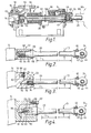
- a helical gear pump 10 having a stator 12 in which is rotatably mounted a rotor 14, the stator and rotor each being provided with a helical gear formation, one of them with a gear formation with n starts and the other with a gear formation of n + 1 starts.
- a barrel 16 Surrounding the stator 12 is a barrel 16 which is bolted to an inlet casing 18 and an outlet casing (not shown).
- a flexible elongate drive shaft 20 is connected to the rotor 14 by a rigid connection 22 to be described in detail below.
- the drive shaft 20 is provided with a pivotal connection 24 to a power transmission rotary member 26.
- This member 26 is keyed to a shaft 28 of a motor 30.
- the member 26 is formed integrally with a rotary tube 32 which is mounted in bearings 34 provided with a seal 36. Where the rotary tubes 32 passes into the inlet casing 18, a gland 38 is provided.
- the pivotal connection 24 includes a pivot pin 40 passing through a bush 42 engaged in an opening 44 in the drive shaft 20. Adjacent the pivot pin 40 the drive shaft is provided with a surrounding sealing ring 46.
- the rigid connection 22 to the rotor 14 comprises a shaped end portion 48 of the flexible drive shaft 20, engaged in a correspondingly shaped recess 50 in the rotor.
- the end portion is locked rigidly into the recess by grub screws 52 which themselves are prevented from loosening by a cover 54 held by locking screws 56.
- FIG. 2 A slightly modified arrangement is shown in Figure 2 in which the rotor shaft 20 is provided with an identical pivotal connection 24 to that described above. This Figure shows more clearly the positioning of the bush 42 and pivot pin 40 in the opening 44.
- the rigid connection 22 in this instance is provided by an extension 60 on the rotor 14 being provided with the threaded bore 64 into which is screwed a threaded end 62 of the drive shaft.
- the bore 64 includes a widened portion 65 having an annular chamfer 66 engaged by a corresponding annular chamfer on thickened portion 68 of the drive shaft.
- Figure 2 illustrates the length L and the diameter D of the drive shaft, the length L being measured on the uniform diameter portion of the drive shaft.
- the rigid connection 22 is provided by forming in an extension 70 of the rotor 14, a threaded bore 74 in which is screwed a threaded shaft 72 having an end portion 76 extending beyond the threaded part 72 and provided with a chamfer 76.
- a transverse bore 80 intersects the axial threaded bore 74 and is threaded at its outer portion. Inserted into this bore is a locking element 82 having a chamfer 84. Threaded into the bore 80 is a plug 86 adapted to force the locking element downwardly, as illustrated in Figure 3, so that the two chamfers 76, 84 are in abutting locking relation, thereby preventing the shaft 20 from rotating.
- FIG. 4 shows the rotor 14 provided with an extension 90 having an axial bore 91 formed therein into which is inserted an adaptor 92.
- This adaptor includes a tapered bore 93 into which is inserted the tapered end 94 of the drive shaft 20.
- a bolt 95 is screwed into a threaded bore 96 in the end of the rotor.
- Adaptor 92 in turn is held in place on the rotor extension 90 by a number of further bolts 97 engaged in threaded bores 98 therein.
- the tapers 93 and 94 are of the "Morse taper" type having the appropriate angle to cause the two parts to lock together against relative rotational movement.
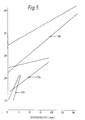
- the diameter of the shaft 10, and its length, will depend largely upon the material used, the degree of eccentricity which has to be catered for and also the torque which has to be transmitted.
- L is the length of that part of the shaft which has a constant section modulus.
- D is the diameter of the shaft which, in each case, is a solid shaft of circular cross-section.
- the values have been plotted for shafts for pumps of various stages.
- Figure 5 shows plotted values for shafts of one, three and six stage pumps
- Figure 6 shows plotted values for shafts of two and four stage pumps.
- a stage refers to the chamber defined between rotor and stator where they engage sealingly at axially spaced zones.
- the L:D ratio for a shaft according to the invention for a single stage pump should preferably not lie below the lower limit of the zone indicated by reference numeral 100.
- the L:D ratio preferably lies within that zone. Where the length of shaft is of no consequence as for instance in borehole pumps, then the L:D ratio may lie above the upper limit of the zone 100.
- the zone for the L:D ratios of shafts for two stage pumps is indicated by reference numeral 102.
- the L:D ratio for a shaft for a two stage pump should not lie below the lower liumt of zone 102.
- This zone 102 is interpreted similarly to zone 100.
- zones for the L:D ratios of shafts for three four and six stage pumps are indicated by reference numerals 104, 106 and 108 respectively. These zones are interpreted similarly to zones 100 and 102.
- the graphs have been plotted for shafts of EN57T material. It emerges from the graphs that the L:D ratios vary from about 20:1 to 40:1 depending on the circumstances of each application.
- the L:D ratio may be as low as about 15 to 1 of EN57T is used as a shaft material.
- the L:D ratio in extreme cases may be as low as about 10 to 1.
Landscapes
- Engineering & Computer Science (AREA)
- General Engineering & Computer Science (AREA)
- Mechanical Engineering (AREA)
- Ocean & Marine Engineering (AREA)
- Health & Medical Sciences (AREA)
- Oral & Maxillofacial Surgery (AREA)
- Rotary Pumps (AREA)
- Flexible Shafts (AREA)
- Shafts, Cranks, Connecting Bars, And Related Bearings (AREA)
Applications Claiming Priority (2)
| Application Number | Priority Date | Filing Date | Title |
|---|---|---|---|
| ZA842111 | 1984-03-21 | ||
| ZA842111 | 1984-03-21 |
Publications (1)
| Publication Number | Publication Date |
|---|---|
| EP0155755A2 true EP0155755A2 (de) | 1985-09-25 |
Family
ID=25577226
Family Applications (1)
| Application Number | Title | Priority Date | Filing Date |
|---|---|---|---|
| EP85300705A Withdrawn EP0155755A2 (de) | 1984-03-21 | 1985-02-01 | Biegsame Antriebswelle |
Country Status (5)
| Country | Link |
|---|---|
| EP (1) | EP0155755A2 (de) |
| AU (1) | AU3901485A (de) |
| DK (1) | DK124685A (de) |
| GB (1) | GB2156042A (de) |
| NO (1) | NO851117L (de) |
Cited By (5)
| Publication number | Priority date | Publication date | Assignee | Title |
|---|---|---|---|---|
| EP0399696A1 (de) * | 1989-05-17 | 1990-11-28 | Mono Pumps Limited | Biegsame Antriebswelle |
| EP0638734A1 (de) * | 1993-08-13 | 1995-02-15 | Mono Pumps Limited | Biegsame Antriebswelle und Verfahren zu ihrer Herstellung |
| EP0845597A1 (de) * | 1996-12-02 | 1998-06-03 | Mono Pumps Limited | Flexible Antriebswelle und Antriebswellen-Rotormontage |
| EP1083336A3 (de) * | 1999-09-09 | 2002-10-23 | Netzsch Mohnopumpen GmbH | Exzenterschneckenpumpen-Anschlussvorrichtung |
| EP2295800A3 (de) * | 2009-08-20 | 2012-06-13 | BARTEC Dispensing Technology GmbH | Exzenterschneckenpumpe |
Families Citing this family (3)
| Publication number | Priority date | Publication date | Assignee | Title |
|---|---|---|---|---|
| MX9203982A (es) * | 1991-08-30 | 1993-02-01 | Xerox Corp | Conjunto de eje impulsor, flexible, moldeado de una sola pieza. |
| GB2311588B (en) * | 1996-12-02 | 1998-03-04 | Mono Pumps Ltd | Flexible drive shaft and drive shaft and rotor assembly |
| WO2013096462A1 (en) * | 2011-12-20 | 2013-06-27 | R. Morley Inc. | Shaft for rotating machinery and methods of making and using same |
Family Cites Families (1)
| Publication number | Priority date | Publication date | Assignee | Title |
|---|---|---|---|---|
| GB839292A (en) * | 1957-08-05 | 1960-06-29 | Gen Motors Corp | Improved rotary power transmission shaft |
-
1985
- 1985-02-01 EP EP85300705A patent/EP0155755A2/de not_active Withdrawn
- 1985-02-01 GB GB08502582A patent/GB2156042A/en not_active Withdrawn
- 1985-02-21 AU AU39014/85A patent/AU3901485A/en not_active Abandoned
- 1985-03-20 DK DK124685A patent/DK124685A/da not_active Application Discontinuation
- 1985-03-20 NO NO851117A patent/NO851117L/no unknown
Cited By (6)
| Publication number | Priority date | Publication date | Assignee | Title |
|---|---|---|---|---|
| EP0399696A1 (de) * | 1989-05-17 | 1990-11-28 | Mono Pumps Limited | Biegsame Antriebswelle |
| AU635738B2 (en) * | 1989-05-17 | 1993-04-01 | Mono Pumps Limited | Flexible drive shaft |
| EP0638734A1 (de) * | 1993-08-13 | 1995-02-15 | Mono Pumps Limited | Biegsame Antriebswelle und Verfahren zu ihrer Herstellung |
| EP0845597A1 (de) * | 1996-12-02 | 1998-06-03 | Mono Pumps Limited | Flexible Antriebswelle und Antriebswellen-Rotormontage |
| EP1083336A3 (de) * | 1999-09-09 | 2002-10-23 | Netzsch Mohnopumpen GmbH | Exzenterschneckenpumpen-Anschlussvorrichtung |
| EP2295800A3 (de) * | 2009-08-20 | 2012-06-13 | BARTEC Dispensing Technology GmbH | Exzenterschneckenpumpe |
Also Published As
| Publication number | Publication date |
|---|---|
| DK124685D0 (da) | 1985-03-20 |
| AU3901485A (en) | 1985-09-26 |
| DK124685A (da) | 1985-09-22 |
| NO851117L (no) | 1985-09-23 |
| GB2156042A (en) | 1985-10-02 |
| GB8502582D0 (en) | 1985-03-06 |
Similar Documents
| Publication | Publication Date | Title |
|---|---|---|
| US5135060A (en) | Articulated coupling for use with a downhole drilling apparatus | |
| US5139400A (en) | Progressive cavity drive train | |
| US5048622A (en) | Hermetically sealed progressive cavity drive train for use in downhole drilling | |
| US6183226B1 (en) | Progressive cavity motors using composite materials | |
| US5135059A (en) | Borehole drilling motor with flexible shaft coupling | |
| US5525146A (en) | Rotary gas separator | |
| US4391547A (en) | Quick release downhole motor coupling | |
| US4676725A (en) | Moineau type gear mechanism with resilient sleeve | |
| US6461128B2 (en) | Progressive cavity helical device | |
| US4923376A (en) | Moineau pump with rotating closed end outer member and nonrotating hollow inner member | |
| US10508493B2 (en) | Universal joint | |
| US20110129375A1 (en) | Work extraction from downhole progressive cavity devices | |
| US5007491A (en) | Downhole drilling apparatus progressive cavity drive train with sealed coupling | |
| EP0934464A1 (de) | Exzenter-schneckenpumpe | |
| US3612734A (en) | Rotary pump or motor with an axially rotating rotor | |
| EP0155755A2 (de) | Biegsame Antriebswelle | |
| US5447472A (en) | Articulated coupling for use with a progressive cavity apparatus | |
| US5007490A (en) | Progressive cavity drive train with elastomeric joint assembly for use in downhole drilling | |
| DE69401384T2 (de) | Schraubenfluidmaschine | |
| US20030181245A1 (en) | Downhole universal joint assembly | |
| EP0657649A1 (de) | Rotor und biegsame Antriebswelle Einheit | |
| US4363603A (en) | Pump impeller assembly with anti-rotation device | |
| US3602604A (en) | Pump construction | |
| CA1091051A (en) | Rotor drive coupling for progressing cavity pump | |
| JP5097924B2 (ja) | ポンプ装置 |
Legal Events
| Date | Code | Title | Description |
|---|---|---|---|
| PUAI | Public reference made under article 153(3) epc to a published international application that has entered the european phase |
Free format text: ORIGINAL CODE: 0009012 |
|
| AK | Designated contracting states |
Designated state(s): BE DE FR IT NL SE |
|
| STAA | Information on the status of an ep patent application or granted ep patent |
Free format text: STATUS: THE APPLICATION HAS BEEN WITHDRAWN |
|
| 18W | Application withdrawn |
Withdrawal date: 19861006 |
|
| RIN1 | Information on inventor provided before grant (corrected) |
Inventor name: PAYNE, STANLEY ASHBOURNE EATON |