EP0155775B1 - Pomme d'arrosoir - Google Patents
Pomme d'arrosoir Download PDFInfo
- Publication number
- EP0155775B1 EP0155775B1 EP85301255A EP85301255A EP0155775B1 EP 0155775 B1 EP0155775 B1 EP 0155775B1 EP 85301255 A EP85301255 A EP 85301255A EP 85301255 A EP85301255 A EP 85301255A EP 0155775 B1 EP0155775 B1 EP 0155775B1
- Authority
- EP
- European Patent Office
- Prior art keywords
- ring
- spray
- apertures
- wall
- adjacent
- Prior art date
- Legal status (The legal status is an assumption and is not a legal conclusion. Google has not performed a legal analysis and makes no representation as to the accuracy of the status listed.)
- Expired
Links
- 239000007921 spray Substances 0.000 title claims description 97
- XLYOFNOQVPJJNP-UHFFFAOYSA-N water Substances O XLYOFNOQVPJJNP-UHFFFAOYSA-N 0.000 claims description 41
- 230000002093 peripheral effect Effects 0.000 claims description 22
- 238000005507 spraying Methods 0.000 claims description 4
- 239000008400 supply water Substances 0.000 claims description 2
- 238000009434 installation Methods 0.000 description 2
- 239000007788 liquid Substances 0.000 description 2
- 230000000694 effects Effects 0.000 description 1
- 239000012528 membrane Substances 0.000 description 1
- 230000004048 modification Effects 0.000 description 1
- 238000012986 modification Methods 0.000 description 1
- 230000000717 retained effect Effects 0.000 description 1
Images

Classifications
-
- B—PERFORMING OPERATIONS; TRANSPORTING
- B05—SPRAYING OR ATOMISING IN GENERAL; APPLYING FLUENT MATERIALS TO SURFACES, IN GENERAL
- B05B—SPRAYING APPARATUS; ATOMISING APPARATUS; NOZZLES
- B05B1/00—Nozzles, spray heads or other outlets, with or without auxiliary devices such as valves, heating means
- B05B1/22—Spouts
-
- B—PERFORMING OPERATIONS; TRANSPORTING
- B05—SPRAYING OR ATOMISING IN GENERAL; APPLYING FLUENT MATERIALS TO SURFACES, IN GENERAL
- B05B—SPRAYING APPARATUS; ATOMISING APPARATUS; NOZZLES
- B05B1/00—Nozzles, spray heads or other outlets, with or without auxiliary devices such as valves, heating means
- B05B1/30—Nozzles, spray heads or other outlets, with or without auxiliary devices such as valves, heating means designed to control volume of flow, e.g. with adjustable passages
- B05B1/32—Nozzles, spray heads or other outlets, with or without auxiliary devices such as valves, heating means designed to control volume of flow, e.g. with adjustable passages in which a valve member forms part of the outlet opening
- B05B1/323—Nozzles, spray heads or other outlets, with or without auxiliary devices such as valves, heating means designed to control volume of flow, e.g. with adjustable passages in which a valve member forms part of the outlet opening the valve member being actuated by the pressure of the fluid to be sprayed
Definitions
- the present invention relates to a water spraying device especially a shower bath spray head, according to the pre-characterizing part of claim 1.
- Fluctuations in water pressure at spray heads causes the force of water emitted through the spray head orifices to vary.
- the "spray” is said to be hard, whilst at low pressures a “soft” spray results and at very low pressures there may be a total loss in spray pattern.
- the "spray” be "soft” although at the same time, a definite or true spray pattern is required to be retained.
- This effect is achieved by providing that the pressure of water emitted from the spray apertures is controlled by means contained within the spray head whereby the size of the spray apertures is increased with increasing liquid pressure, a decrease in size of the apertures occurring as the pressure drops again.
- the present invention thus provides a water spraying device comprising: a spray head (1) and means to supply water under pressure to a chamber located within said head, said head including a face element forming an outer wall of said chamber comprising a plurality of annular concentric spray rings (3, 4, 5; 23, 24, 25; 43, 44, 45), each said ring having an inner and an outer peripheral wall extending axially of the said face element, the outer peripheral wall of one ring lying adjacent the inner peripheral wall of a second ring, the spray ring apertures (9a, 11, 11 a, 22, 27, 33, 42, 54) being formed by axially directed serrations (9, 10,10a, 26,32,21,41,53) cut in the peripheral wall of at least one of two adjacent rings and communicating with said chamber to define a spray pattern of water emitted through said apertures (EP-A2-0080856), characterised in that said spray head (1) further includes means (2, 24, 44, 8, 14, 31, 51) for-controlling the pressure of water emitted from the said apertures, said means (2,24
- the size of the apertures at zero flow rate is such that a true spray pattern will be achieved at water pressures of 2.65 cm Hg (36 inches water) and above.
- control of the pressure of water emitted through the apertures may be obtained by providing that at least one of the spray rings is movable against a resilient means located within the spray heads and in response to an increase or decrease in water pressure, the spray rings being constructed such that the said movement results in an increase or decrease in water pressure, the spray rings being constructed such that the said movement results in an increase or decrease in the size of the spray ring apertures.
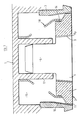
- the handset body 1 includes a spray ring assembly 2 having an outer spray ring 3 attached to the body 1, and inner spray rings 4 and 5 fixed in relation to each other and carried on a centre cylindrical member 6 which is in sliding engagement with tubular member 7 extending inwardly of body 1.
- Serrations 9 on central spray ring 5 provide in co-operation with the inner wal of ring 4 a first inner ring of apertures 9a in the face of the spray head which apertures communicate via the serrations with the hollow interior 15 of the body 1.
- Serrations 10 formed on the inner wall of the outer spray ring 3 provide in co-operation with the uppermost corner of the outer wall of ring 4, a second ring of apertures 11 in the face of the spray head which also communicates with interior 15 of body 1.
- Atension spring 8 is located between body 1 and an inner groove 8a in ring 5 and retains spray rings 4 and 5 at their innermost position.
- tension spring 8 is omitted and is replaced by tension spring 14 (shown in dotted outline) that is located about tubular members 12 and 13 (shown in dotted outline) extending inwardly of spray ring assembly 2 and body 1 respectively.
- Figure 2 is a further variation of that of Figure 1, the inner spray ring 4 being formed with shoulders 54 about which one end of tension spring 18 is wrapped to retain the spray ring assembly in its innermost position, the other end being wrapped about the upper portion 7a of the tubular portion 7.
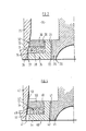
- the outer spray ring 23, the inner annular spray ring 24 and central portion 25 are all located in positions fixed in relation to the spray head body.
- Serrations 21 formed in the outer wall of portion 25 provide apertures 22 and serrations 26 formed in the outer wall of spray ring 24 provide apertures 27.
- Serrations 26, are, however, deeper than serrations 21 thereby providing that the apertures 27 are substantially larger than apertures 22.
- the inner portion of spray ring 24 is machined to provide a flat annular surface 28, parallel to the face of the spray ring, and a shoulder portion 29.
- a closed-cell sponge or wavey spring washer 31 is located on shoulder 28 and supports an inner floating spray ring 30 the outer edges of which include serration 32 which form a ring of inner apertures 33 having the same size as apertures 22.
- water enters the area 35 behind the spray ring assembly 20 and is emitted as a spray from apertures 22 and 27.
- the inner spray ring 30 will be pressed against the sponge or wavey washer thereby increasing the size of aperture 33 to allow an increased flow of water therethrough whereby the spray emitted from apertures 22 and 27 remains "soft".
- a reduction in water pressure will cause spray ring 30 to be returned towards its original position by the resilient sponge or washer 31, which movement increases the pressure of water entering the space 34 and maintains a true spray pattern from apertures 22 and 27.
- a spray ring assembly only half of which is shown, generally indicated at 40 includes an outer spray ring 43, an inner spray ring 44 and a central portion 25, secured in fixed relationship to the spray head body.
- Serrations 41, formed in the outer peripheral wall of spray ring 44 define in co-operation with the inner peripheral wall of portion 25, spray apertures 42.
- Spray ring 44 is dimensioned to provide an annular gap 46 between the outer spray ring 43 and the inner spray ring 44 which gap is filled by a web 47 that may consist of four or six location membranes.
- the upper portion of spray ring 44 is machined to provide a flat annular surface 48 and a shoulder 49.
- a closed cell sponge or wavey washer 51 is located on shoulder 48 and supports an inner annular floating spray ring 50.
- Serrations 53 are cut in upper portion 52 inner peripheral wall of outer spray ring 43 to form, in co-operation with floating ring 50 a second ring of apertures 54, having the same dimensions as apertures 42.
Landscapes
- Nozzles (AREA)
Claims (8)
Applications Claiming Priority (2)
| Application Number | Priority Date | Filing Date | Title |
|---|---|---|---|
| GB848404976A GB8404976D0 (en) | 1984-02-25 | 1984-02-25 | Spray heads |
| GB8404976 | 1984-02-25 |
Publications (2)
| Publication Number | Publication Date |
|---|---|
| EP0155775A1 EP0155775A1 (fr) | 1985-09-25 |
| EP0155775B1 true EP0155775B1 (fr) | 1988-04-27 |
Family
ID=10557187
Family Applications (1)
| Application Number | Title | Priority Date | Filing Date |
|---|---|---|---|
| EP85301255A Expired EP0155775B1 (fr) | 1984-02-25 | 1985-02-25 | Pomme d'arrosoir |
Country Status (7)
| Country | Link |
|---|---|
| US (1) | US4690334A (fr) |
| EP (1) | EP0155775B1 (fr) |
| KR (1) | KR850006511A (fr) |
| AU (1) | AU568916B2 (fr) |
| DE (1) | DE3562316D1 (fr) |
| GB (2) | GB8404976D0 (fr) |
| IE (1) | IE55989B1 (fr) |
Families Citing this family (6)
| Publication number | Priority date | Publication date | Assignee | Title |
|---|---|---|---|---|
| US5323807A (en) * | 1993-08-18 | 1994-06-28 | Delavan Inc. | Stop drop valve |
| KR100752308B1 (ko) * | 2001-05-18 | 2007-08-29 | 주식회사 포스코 | 변동수압에 대한 유효살수거리 제어용 레인건 |
| CN101187958B (zh) * | 2006-11-20 | 2012-05-30 | 国际商业机器公司 | 生成集成电子电路的布图的方法和系统 |
| WO2011035035A2 (fr) * | 2009-09-16 | 2011-03-24 | Sta-Rite Industries, Llc | Système à baïonnette pour buses de pulvérisation |
| US10603681B2 (en) * | 2017-03-06 | 2020-03-31 | Engineered Spray Components LLC | Stacked pre-orifices for sprayer nozzles |
| CN118950391B (zh) * | 2024-10-17 | 2025-01-24 | 赢胜节能集团股份有限公司 | 一种玻璃棉保温板用防堵式双面喷胶装置 |
Family Cites Families (11)
| Publication number | Priority date | Publication date | Assignee | Title |
|---|---|---|---|---|
| GB664125A (en) * | 1948-10-06 | 1952-01-02 | Wander Ag Dr A | Process for the production of cholesteryl esters chlorinated in position 7 |
| US2727784A (en) * | 1952-12-02 | 1955-12-20 | Crane Co | Showerhead or the like |
| US2948477A (en) * | 1958-02-20 | 1960-08-09 | Speakman Co | Automatic shower head |
| US2990123A (en) * | 1959-02-18 | 1961-06-27 | American Radiator & Standard | Shower head |
| GB1111126A (en) * | 1964-05-12 | 1968-04-24 | Crosweller & Co Ltd W | Improvements in, or relating to, spray nozzles |
| AT249597B (de) * | 1965-06-23 | 1966-09-26 | Seidl Karl | Brausekopf, insbesodere von Hand- oder Schlauchbrausen, mit Überdrucksicherung |
| US3383051A (en) * | 1966-01-10 | 1968-05-14 | Speakman Co | Shower head |
| US3380664A (en) * | 1966-03-16 | 1968-04-30 | Nat Distillers Chem Corp | Adjustable shower head |
| US4000857A (en) * | 1974-07-17 | 1977-01-04 | Moen Alfred M | Flow control aerator |
| US4275843A (en) * | 1979-11-14 | 1981-06-30 | Stanadyne, Inc. | Automatically adjustable shower head |
| GB2110289B (en) * | 1981-11-27 | 1985-04-24 | Triton Aquatherm | Fastening for shower heads |
-
1984
- 1984-02-25 GB GB848404976A patent/GB8404976D0/en active Pending
-
1985
- 1985-02-22 IE IE440/85A patent/IE55989B1/en not_active IP Right Cessation
- 1985-02-22 KR KR1019850001117A patent/KR850006511A/ko not_active Withdrawn
- 1985-02-22 GB GB08504635A patent/GB2155361B/en not_active Expired
- 1985-02-22 AU AU39097/85A patent/AU568916B2/en not_active Ceased
- 1985-02-25 US US06/705,081 patent/US4690334A/en not_active Expired - Fee Related
- 1985-02-25 EP EP85301255A patent/EP0155775B1/fr not_active Expired
- 1985-02-25 DE DE8585301255T patent/DE3562316D1/de not_active Expired
Also Published As
| Publication number | Publication date |
|---|---|
| GB8504635D0 (en) | 1985-03-27 |
| AU3909785A (en) | 1985-09-05 |
| GB2155361B (en) | 1988-08-24 |
| EP0155775A1 (fr) | 1985-09-25 |
| AU568916B2 (en) | 1988-01-14 |
| US4690334A (en) | 1987-09-01 |
| IE850440L (en) | 1985-08-25 |
| GB8404976D0 (en) | 1984-03-28 |
| DE3562316D1 (en) | 1988-06-01 |
| GB2155361A (en) | 1985-09-25 |
| KR850006511A (ko) | 1985-10-14 |
| IE55989B1 (en) | 1991-03-13 |
Similar Documents
| Publication | Publication Date | Title |
|---|---|---|
| US4000857A (en) | Flow control aerator | |
| US4838486A (en) | Shower head | |
| EP0155775B1 (fr) | Pomme d'arrosoir | |
| US3409050A (en) | Flow restrictor | |
| US4136407A (en) | Under spray arrangement for toilet bowls and the like | |
| CA1135752A (fr) | Pomme de douche a reglage automatique | |
| US4991780A (en) | Duocone spray nozzle | |
| KR101478608B1 (ko) | 절수기구 | |
| JPH08320074A (ja) | ポペット弁用弁境界部構造 | |
| US4923115A (en) | Mixing valve apparatus | |
| US4724864A (en) | Two-way flow control valve | |
| US4364523A (en) | Flow control technique | |
| CA1057647A (fr) | Aerateur a regulateur de debit | |
| JPS5718567A (en) | Vibro-isolating device of spool valve in control valve for power steering mechanism | |
| WO1984002828A1 (fr) | Dispositif d'alimentation a egouttement regule par la pression | |
| US2998930A (en) | Water aerator diaphragms | |
| US3064557A (en) | Flow restrainer | |
| CN105546211B (zh) | 流量调节器及节水器及水流调节器 | |
| JPH0454496Y2 (fr) | ||
| CA1294513C (fr) | Structure a piston pour robinet reducteur de pression | |
| GB2193446A (en) | Spray heads | |
| CN205446918U (zh) | 流量调节器及节水器及水流调节器 | |
| JPS5797968A (en) | Flow velocity control valve | |
| KR920000502Y1 (ko) | 수격방지용 급수밸브 | |
| JPS57208364A (en) | Fluid flow rate regulating valve |
Legal Events
| Date | Code | Title | Description |
|---|---|---|---|
| PUAI | Public reference made under article 153(3) epc to a published international application that has entered the european phase |
Free format text: ORIGINAL CODE: 0009012 |
|
| AK | Designated contracting states |
Designated state(s): BE DE FR IT NL SE |
|
| 17P | Request for examination filed |
Effective date: 19851211 |
|
| 17Q | First examination report despatched |
Effective date: 19860724 |
|
| RAP1 | Party data changed (applicant data changed or rights of an application transferred) |
Owner name: TRITON PLC |
|
| ITF | It: translation for a ep patent filed | ||
| GRAA | (expected) grant |
Free format text: ORIGINAL CODE: 0009210 |
|
| AK | Designated contracting states |
Kind code of ref document: B1 Designated state(s): BE DE FR IT NL SE |
|
| REF | Corresponds to: |
Ref document number: 3562316 Country of ref document: DE Date of ref document: 19880601 |
|
| ET | Fr: translation filed | ||
| PLBI | Opposition filed |
Free format text: ORIGINAL CODE: 0009260 |
|
| 26 | Opposition filed |
Opponent name: HANS GROHE GMBH & CO. KG Effective date: 19890127 |
|
| NLR1 | Nl: opposition has been filed with the epo |
Opponent name: HANS GROHE GMBH & CO. KG |
|
| ITTA | It: last paid annual fee | ||
| PLBN | Opposition rejected |
Free format text: ORIGINAL CODE: 0009273 |
|
| STAA | Information on the status of an ep patent application or granted ep patent |
Free format text: STATUS: OPPOSITION REJECTED |
|
| 27O | Opposition rejected |
Effective date: 19910221 |
|
| NLR2 | Nl: decision of opposition | ||
| EAL | Se: european patent in force in sweden |
Ref document number: 85301255.7 |
|
| PGFP | Annual fee paid to national office [announced via postgrant information from national office to epo] |
Ref country code: SE Payment date: 19990215 Year of fee payment: 15 |
|
| PGFP | Annual fee paid to national office [announced via postgrant information from national office to epo] |
Ref country code: DE Payment date: 19990430 Year of fee payment: 15 |
|
| PG25 | Lapsed in a contracting state [announced via postgrant information from national office to epo] |
Ref country code: SE Free format text: LAPSE BECAUSE OF NON-PAYMENT OF DUE FEES Effective date: 20000226 |
|
| EUG | Se: european patent has lapsed |
Ref document number: 85301255.7 |
|
| PG25 | Lapsed in a contracting state [announced via postgrant information from national office to epo] |
Ref country code: DE Free format text: LAPSE BECAUSE OF NON-PAYMENT OF DUE FEES Effective date: 20001201 |
|
| PGFP | Annual fee paid to national office [announced via postgrant information from national office to epo] |
Ref country code: FR Payment date: 20031216 Year of fee payment: 20 |
|
| PGFP | Annual fee paid to national office [announced via postgrant information from national office to epo] |
Ref country code: BE Payment date: 20031224 Year of fee payment: 20 |
|
| PGFP | Annual fee paid to national office [announced via postgrant information from national office to epo] |
Ref country code: NL Payment date: 20040227 Year of fee payment: 20 |
|
| PG25 | Lapsed in a contracting state [announced via postgrant information from national office to epo] |
Ref country code: NL Free format text: LAPSE BECAUSE OF EXPIRATION OF PROTECTION Effective date: 20050225 |
|
| BE20 | Be: patent expired |
Owner name: *TRITON P.L.C. Effective date: 20050225 |
|
| NLV7 | Nl: ceased due to reaching the maximum lifetime of a patent |
Effective date: 20050225 |
|
| BE20 | Be: patent expired |
Owner name: *TRITON P.L.C. Effective date: 20050225 |
|
| PLAB | Opposition data, opponent's data or that of the opponent's representative modified |
Free format text: ORIGINAL CODE: 0009299OPPO |