EP0155836A2 - Lingotière pour la coulée continue horizontale - Google Patents
Lingotière pour la coulée continue horizontale Download PDFInfo
- Publication number
- EP0155836A2 EP0155836A2 EP85301854A EP85301854A EP0155836A2 EP 0155836 A2 EP0155836 A2 EP 0155836A2 EP 85301854 A EP85301854 A EP 85301854A EP 85301854 A EP85301854 A EP 85301854A EP 0155836 A2 EP0155836 A2 EP 0155836A2
- Authority
- EP
- European Patent Office
- Prior art keywords
- mould
- continuous casting
- tube
- horizontal continuous
- duct
- Prior art date
- Legal status (The legal status is an assumption and is not a legal conclusion. Google has not performed a legal analysis and makes no representation as to the accuracy of the status listed.)
- Granted
Links
Images

Classifications
-
- B—PERFORMING OPERATIONS; TRANSPORTING
- B22—CASTING; POWDER METALLURGY
- B22D—CASTING OF METALS; CASTING OF OTHER SUBSTANCES BY THE SAME PROCESSES OR DEVICES
- B22D11/00—Continuous casting of metals, i.e. casting in indefinite lengths
- B22D11/04—Continuous casting of metals, i.e. casting in indefinite lengths into open-ended moulds
- B22D11/045—Continuous casting of metals, i.e. casting in indefinite lengths into open-ended moulds for horizontal casting
Definitions
- a horizontal continuous casting mould to consist of a mould tube, which defines the mould passage, mounted in a housing structure.
- the housing structure provides liquid cooling for molten metal passed along the mould passage so that the molten metal begins to solidify in the mould passage and for the cross-section of the casting to be determined by the cross-section of the mould passage.
- a horizontal continuous casting mould comprises a housing structure, a mould tube defining a mould passage, and means by which liquid coolant is applied to the outside of the mould tube, characterised in that the housing structure defines an opening therethrough, the opening being arranged with its longitudinal axis substantially horizontal; and the mould tube is removably secured to the structure such that it extends through the opening with the longitudinal axis of the mould passage substantially horizontal.
- annular spacer is movably mounted in the structure to surround the mould tube and provide an annular duct between the spacer and the outer surface of the mould tube, the structure providing means by which liquid coolant is caused to flow along the duct.
- the housing structure is arranged such that liquid coolant is brought into contact with the outer surface of whichever mould tube is in use. It is most desirable that a predetermined flow of liquid coolant along the duct takes place whatever the size of the mould tube. To this end, it is desirable to replace the annular spacer each time the size of the mould tube is changed to keep the cross-section of the annular duct between the spacer and the mould tube at a predetermined value.
- the longitudinal axis of the mould passage is always in a fixed relation with the longitudinal axis of the opening in the housing structure.
- the longitudinal axis of the mould passage is coincident with the longitudinal axis of the opening. In this way, the pass-line of the casting produced in the mould is always the same regardless of the cross-section of the casting.
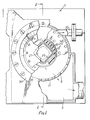
- a horizontal continuous casting mould has a housing structure 1 which is located in the casting position between the supply tundish for the molten metal and a run-out table for the casting, neither of which are shown.
- the housing structure is mainly of fabricated metal plates and it defines a pair of chambers 3, 5 located close to the base of the housing structure.
- the chambers are defined in part by a cylindrical tube 6 which also defines an opening 7 through the structure, the longitudinal axis of the opening being arranged substantially horizontal.
- a tube 9 having an outwardly extending flange at one end is mounted within the opening 7.
- a number of bolts 10 secure the tube 9 to an inwardly extending rib 13 on the tube 6 and thus form an annular enclosure 15.
- a group of holes 17 are provided in the tube 6 and the group of holes at each end are in communication with the respective chambers 3, 5.
- An annular spacer in the form of a tube 20 is removably mounted in the opening 7 and defines an opening 23 of reduced cross-section as compared with that of the opening 7.
- the spacer is conveniently a push fit into the inside of the tube 9.
- One end of the mould tube is sealed into an aperture in an end plate 31 which is removably bolted to one end of the housing structure.
- the other end of the mould tube has an outwardly extending flange 33 which is bolted to an end plate which, in turn, is removably bolted to the other end of the housing structure.
- the longitudinal axis of the mould passage is coincident with the longitudinal axis of the opening 7.
- the outer surface of the mould tube is spaced apart from the spacer 20 which surrounds it to form a duct 28 between them.
- the housing structure provides cooling for the molten metal passed through the mould tube.
- liquid coolant usually water
- water is supplied to the chamber 3 from where it flows out through the openings 17 at the adjacent end of the structure into contact with the outer surface of the mould tube and the spacer.
- Some of the water passes along the duct 28, along the length of the outside of the mould tube and through further openings 17 at the opposite end of the structure into the chamber 5, from where it flows to drain. There is, therefore, a continuous flow of cooling water in contact with the outer surface of the mould tube.
- some of the cooling water which is supplied to the chamber 3 passes through openings in the flange 11 and into the enclosure 15 and out from the enclosure through a further outlet port 35.
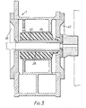
- FIG. 3 shows an alternative form of the continuous casting mould in which a casting of a much smaller cross-section than that shown in Figures 1 and 2 is required.
- the annular spacer and the mould tube shown in Figures 1 and 2 are removed with the end plates 31, 34.
- a new spacer 41 is pushed into the tube 9 and a second mould tube 43 is located in the opening through the housing structure and held in position by new end plates 45, 47.
- the longitudinal axis of the mould tube is still coincident with the longitudinal axis of the opening provided by the housing structure.
- the cooling means provided in the housing remain and a large part of the water from the chamber 3 flows along the duct 28 and into the chamber 5.
- the cross-section of the duct in the arrangement of Figure 3 is substantially as the cross-section of the duct in the arrangements of Figures 1 and 2.
- the horizontal continuous casting mould of this invention may incorporate electro-magnetic stirring of the molten metal passed through the mould tube.
- the solidifying casting is withdrawn from the mould tube using a push-pull cycle withdrawal pattern and this may bring about a surface defect on the produced casting, known as a cold shut crack, a witness mark or a ghost line.
- a surface defect on the produced casting known as a cold shut crack, a witness mark or a ghost line.
- electric coils indicated by the broken line in Figure 2
- the spacer 20 is of magnetically transparent material.
- the material can be caused to give either linear or rotational stirring of the liquid core in the mould tube.
- differential stirring intensity can be applied along the length of the horizontal mould in order to effect the solidification rate of the skin at any point.
Landscapes
- Engineering & Computer Science (AREA)
- Mechanical Engineering (AREA)
- Molds, Cores, And Manufacturing Methods Thereof (AREA)
- Casting Or Compression Moulding Of Plastics Or The Like (AREA)
- Moulds For Moulding Plastics Or The Like (AREA)
- Continuous Casting (AREA)
Priority Applications (1)
| Application Number | Priority Date | Filing Date | Title |
|---|---|---|---|
| AT85301854T ATE35923T1 (de) | 1984-03-19 | 1985-03-18 | Giessform zum horizontalstranggiessen. |
Applications Claiming Priority (2)
| Application Number | Priority Date | Filing Date | Title |
|---|---|---|---|
| GB848407072A GB8407072D0 (en) | 1984-03-19 | 1984-03-19 | Horizontal continuous casting moulds |
| GB8407072 | 1984-03-19 |
Publications (4)
| Publication Number | Publication Date |
|---|---|
| EP0155836A2 true EP0155836A2 (fr) | 1985-09-25 |
| EP0155836A3 EP0155836A3 (en) | 1986-05-14 |
| EP0155836B1 EP0155836B1 (fr) | 1988-07-27 |
| EP0155836B2 EP0155836B2 (fr) | 1993-01-20 |
Family
ID=10558303
Family Applications (1)
| Application Number | Title | Priority Date | Filing Date |
|---|---|---|---|
| EP85301854A Expired - Lifetime EP0155836B2 (fr) | 1984-03-19 | 1985-03-18 | Lingotière pour la coulée continue horizontale |
Country Status (4)
| Country | Link |
|---|---|
| EP (1) | EP0155836B2 (fr) |
| AT (1) | ATE35923T1 (fr) |
| DE (1) | DE3563920D1 (fr) |
| GB (1) | GB8407072D0 (fr) |
Cited By (2)
| Publication number | Priority date | Publication date | Assignee | Title |
|---|---|---|---|---|
| US4714103A (en) * | 1986-10-10 | 1987-12-22 | Mannesmann Demag Corporation | Continuous casting mold |
| US4799533A (en) * | 1986-06-20 | 1989-01-24 | Steel Casting Engineering, Ltd. | Horizontal continuous casting mold |
Family Cites Families (3)
| Publication number | Priority date | Publication date | Assignee | Title |
|---|---|---|---|---|
| US3321008A (en) * | 1963-10-18 | 1967-05-23 | M E A Inc | Apparatus for the continuous casting of metal |
| US3730257A (en) * | 1971-06-24 | 1973-05-01 | Koppers Co Inc | Continuous casting sleeve mold |
| IT1146499B (it) * | 1981-07-30 | 1986-11-12 | Danieli Off Mecc | Lingottiera con cristallizzatore tubolare |
-
1984
- 1984-03-19 GB GB848407072A patent/GB8407072D0/en active Pending
-
1985
- 1985-03-18 DE DE8585301854T patent/DE3563920D1/de not_active Expired
- 1985-03-18 AT AT85301854T patent/ATE35923T1/de not_active IP Right Cessation
- 1985-03-18 EP EP85301854A patent/EP0155836B2/fr not_active Expired - Lifetime
Cited By (2)
| Publication number | Priority date | Publication date | Assignee | Title |
|---|---|---|---|---|
| US4799533A (en) * | 1986-06-20 | 1989-01-24 | Steel Casting Engineering, Ltd. | Horizontal continuous casting mold |
| US4714103A (en) * | 1986-10-10 | 1987-12-22 | Mannesmann Demag Corporation | Continuous casting mold |
Also Published As
| Publication number | Publication date |
|---|---|
| EP0155836B1 (fr) | 1988-07-27 |
| EP0155836A3 (en) | 1986-05-14 |
| DE3563920D1 (en) | 1988-09-01 |
| GB8407072D0 (en) | 1984-04-26 |
| EP0155836B2 (fr) | 1993-01-20 |
| ATE35923T1 (de) | 1988-08-15 |
Similar Documents
| Publication | Publication Date | Title |
|---|---|---|
| US3741280A (en) | Mould for the production of metal ingots | |
| US4239078A (en) | Cooled continuous casting mould | |
| EP1021262B1 (fr) | Procede et dispositif pour commander au moyen de champs electromagnetiques l'ecoulement du metal lors d'une operation de coulee en continu | |
| EP0247768B1 (fr) | Système de moulage modulaire et procédé pour la coulée continue de lingots métalliques | |
| US3888300A (en) | Apparatus for the continuous casting of metals and the like under vacuum | |
| US5178204A (en) | Method and apparatus for rheocasting | |
| EP0155836A2 (fr) | Lingotière pour la coulée continue horizontale | |
| US3527287A (en) | Continuous-casting mold assembly | |
| US4126175A (en) | Electromagnetic mould for the continuous and semicontinuous casting of hollow ingots | |
| EP0117115A1 (fr) | Dispositif de brassage électromagnétique d'une lingotière pour coulée continue des lingots | |
| EP0165316A1 (fr) | Dispositif agitateur electromagnetique pour machine de coulee en continu | |
| US3902543A (en) | Process of electroslag remelting | |
| RU2249493C2 (ru) | Машина для непрерывной горизонтальной разливки металла | |
| CA1133678A (fr) | Moule et methode de coulee continue | |
| EP0251570B1 (fr) | Moule de coulée continue horizontale | |
| SK45298A3 (en) | Equipment for continuous or semi-continuous casting of metals | |
| US6843305B2 (en) | Method and device for controlling stirring in a strand | |
| EP0068320B1 (fr) | Méthode et appareil d'agitation électromagnétique pour une installation de coulée continue du type à deux lignes | |
| US5332024A (en) | Multipurpose mold | |
| EP0153086A1 (fr) | Assemblage formé par un agitateur à induction et une coquille de coulée continue | |
| SE515990C2 (sv) | Anordning för kontinuerlig eller halvkontinuerlig gjutning av metaller | |
| Popelka | Use of Electromagnetic Ingot Molds for Casting Aluminum Ingots | |
| Samsonov et al. | Continuous Horizontal Casting of Iron Plates | |
| JPH0790332B2 (ja) | 連続鋳造装置 | |
| CN1072054C (zh) | 用于薄钢带浇铸装置的浇铸喷嘴 |
Legal Events
| Date | Code | Title | Description |
|---|---|---|---|
| PUAI | Public reference made under article 153(3) epc to a published international application that has entered the european phase |
Free format text: ORIGINAL CODE: 0009012 |
|
| AK | Designated contracting states |
Designated state(s): AT BE CH DE FR GB IT LI LU NL SE |
|
| PUAL | Search report despatched |
Free format text: ORIGINAL CODE: 0009013 |
|
| AK | Designated contracting states |
Kind code of ref document: A3 Designated state(s): AT BE CH DE FR GB IT LI LU NL SE |
|
| 17P | Request for examination filed |
Effective date: 19861113 |
|
| 17Q | First examination report despatched |
Effective date: 19870427 |
|
| GRAA | (expected) grant |
Free format text: ORIGINAL CODE: 0009210 |
|
| AK | Designated contracting states |
Kind code of ref document: B1 Designated state(s): AT BE CH DE FR GB IT LI LU NL SE |
|
| PG25 | Lapsed in a contracting state [announced via postgrant information from national office to epo] |
Ref country code: SE Effective date: 19880727 Ref country code: NL Effective date: 19880727 Ref country code: LI Effective date: 19880727 Ref country code: CH Effective date: 19880727 Ref country code: BE Effective date: 19880727 |
|
| REF | Corresponds to: |
Ref document number: 35923 Country of ref document: AT Date of ref document: 19880815 Kind code of ref document: T |
|
| ITF | It: translation for a ep patent filed | ||
| REF | Corresponds to: |
Ref document number: 3563920 Country of ref document: DE Date of ref document: 19880901 |
|
| ET | Fr: translation filed | ||
| REG | Reference to a national code |
Ref country code: CH Ref legal event code: PL |
|
| NLV1 | Nl: lapsed or annulled due to failure to fulfill the requirements of art. 29p and 29m of the patents act | ||
| PG25 | Lapsed in a contracting state [announced via postgrant information from national office to epo] |
Ref country code: LU Free format text: LAPSE BECAUSE OF NON-PAYMENT OF DUE FEES Effective date: 19890331 |
|
| PLBI | Opposition filed |
Free format text: ORIGINAL CODE: 0009260 |
|
| 26 | Opposition filed |
Opponent name: VOEST ALPINE INDUSTRIEANLAGEN GES.M.B.H. Effective date: 19890413 |
|
| ITTA | It: last paid annual fee | ||
| PUAH | Patent maintained in amended form |
Free format text: ORIGINAL CODE: 0009272 |
|
| STAA | Information on the status of an ep patent application or granted ep patent |
Free format text: STATUS: PATENT MAINTAINED AS AMENDED |
|
| 27A | Patent maintained in amended form |
Effective date: 19930120 |
|
| AK | Designated contracting states |
Kind code of ref document: B2 Designated state(s): AT BE CH DE FR GB IT LI LU NL SE |
|
| ET3 | Fr: translation filed ** decision concerning opposition | ||
| ITF | It: translation for a ep patent filed | ||
| PGFP | Annual fee paid to national office [announced via postgrant information from national office to epo] |
Ref country code: DE Payment date: 19980327 Year of fee payment: 14 |
|
| PGFP | Annual fee paid to national office [announced via postgrant information from national office to epo] |
Ref country code: AT Payment date: 19980330 Year of fee payment: 14 |
|
| PGFP | Annual fee paid to national office [announced via postgrant information from national office to epo] |
Ref country code: FR Payment date: 19980331 Year of fee payment: 14 |
|
| PGFP | Annual fee paid to national office [announced via postgrant information from national office to epo] |
Ref country code: GB Payment date: 19990316 Year of fee payment: 15 |
|
| PG25 | Lapsed in a contracting state [announced via postgrant information from national office to epo] |
Ref country code: AT Free format text: LAPSE BECAUSE OF NON-PAYMENT OF DUE FEES Effective date: 19990318 |
|
| PG25 | Lapsed in a contracting state [announced via postgrant information from national office to epo] |
Ref country code: FR Free format text: LAPSE BECAUSE OF NON-PAYMENT OF DUE FEES Effective date: 19991130 |
|
| REG | Reference to a national code |
Ref country code: FR Ref legal event code: ST |
|
| PG25 | Lapsed in a contracting state [announced via postgrant information from national office to epo] |
Ref country code: DE Free format text: LAPSE BECAUSE OF NON-PAYMENT OF DUE FEES Effective date: 20000101 |
|
| PG25 | Lapsed in a contracting state [announced via postgrant information from national office to epo] |
Ref country code: GB Free format text: LAPSE BECAUSE OF NON-PAYMENT OF DUE FEES Effective date: 20000318 |
|
| GBPC | Gb: european patent ceased through non-payment of renewal fee |
Effective date: 20000318 |
|
| APAH | Appeal reference modified |
Free format text: ORIGINAL CODE: EPIDOSCREFNO |