EP0155876A1 - Method and installation for obtaining solutions with a high percentage of dissolved gas; solutions obtained - Google Patents
Method and installation for obtaining solutions with a high percentage of dissolved gas; solutions obtained Download PDFInfo
- Publication number
- EP0155876A1 EP0155876A1 EP85400353A EP85400353A EP0155876A1 EP 0155876 A1 EP0155876 A1 EP 0155876A1 EP 85400353 A EP85400353 A EP 85400353A EP 85400353 A EP85400353 A EP 85400353A EP 0155876 A1 EP0155876 A1 EP 0155876A1
- Authority
- EP
- European Patent Office
- Prior art keywords
- pressure
- gas
- temperature
- under
- dissolution
- Prior art date
- Legal status (The legal status is an assumption and is not a legal conclusion. Google has not performed a legal analysis and makes no representation as to the accuracy of the status listed.)
- Granted
Links
- 238000000034 method Methods 0.000 title claims description 19
- 238000009434 installation Methods 0.000 title claims description 6
- CURLTUGMZLYLDI-UHFFFAOYSA-N Carbon dioxide Chemical compound O=C=O CURLTUGMZLYLDI-UHFFFAOYSA-N 0.000 claims abstract description 53
- 229910002092 carbon dioxide Inorganic materials 0.000 claims abstract description 27
- 239000001569 carbon dioxide Substances 0.000 claims abstract description 26
- 239000000203 mixture Substances 0.000 claims abstract description 15
- 239000007788 liquid Substances 0.000 claims abstract description 13
- PXBRQCKWGAHEHS-UHFFFAOYSA-N dichlorodifluoromethane Chemical compound FC(F)(Cl)Cl PXBRQCKWGAHEHS-UHFFFAOYSA-N 0.000 claims abstract description 8
- 235000019404 dichlorodifluoromethane Nutrition 0.000 claims abstract description 7
- 239000004338 Dichlorodifluoromethane Substances 0.000 claims abstract description 5
- 230000005587 bubbling Effects 0.000 claims abstract 2
- 150000002430 hydrocarbons Chemical class 0.000 claims description 11
- 239000004215 Carbon black (E152) Substances 0.000 claims description 10
- 238000004090 dissolution Methods 0.000 claims description 10
- 229930195733 hydrocarbon Natural products 0.000 claims description 10
- KYKAJFCTULSVSH-UHFFFAOYSA-N chloro(fluoro)methane Chemical compound F[C]Cl KYKAJFCTULSVSH-UHFFFAOYSA-N 0.000 claims description 8
- 239000013529 heat transfer fluid Substances 0.000 claims description 8
- 239000007921 spray Substances 0.000 claims description 7
- 230000001105 regulatory effect Effects 0.000 claims description 6
- 238000005507 spraying Methods 0.000 claims description 6
- 238000009835 boiling Methods 0.000 claims description 5
- 238000001816 cooling Methods 0.000 claims description 4
- 238000004064 recycling Methods 0.000 claims description 4
- 238000005057 refrigeration Methods 0.000 claims description 4
- 230000001276 controlling effect Effects 0.000 claims description 3
- 239000004033 plastic Substances 0.000 claims description 3
- 229920003023 plastic Polymers 0.000 claims description 3
- 238000011144 upstream manufacturing Methods 0.000 claims description 3
- OHMHBGPWCHTMQE-UHFFFAOYSA-N 2,2-dichloro-1,1,1-trifluoroethane Chemical compound FC(F)(F)C(Cl)Cl OHMHBGPWCHTMQE-UHFFFAOYSA-N 0.000 claims description 2
- 239000000443 aerosol Substances 0.000 claims description 2
- 230000006835 compression Effects 0.000 claims description 2
- 238000007906 compression Methods 0.000 claims description 2
- 238000005188 flotation Methods 0.000 claims description 2
- 229920001821 foam rubber Polymers 0.000 claims description 2
- 238000012354 overpressurization Methods 0.000 claims description 2
- 238000011084 recovery Methods 0.000 claims description 2
- 239000000243 solution Substances 0.000 claims 9
- 239000006260 foam Substances 0.000 claims 1
- 239000012047 saturated solution Substances 0.000 claims 1
- 230000000694 effects Effects 0.000 abstract description 2
- 150000005827 chlorofluoro hydrocarbons Chemical class 0.000 abstract 8
- 229920006395 saturated elastomer Polymers 0.000 description 3
- 239000002904 solvent Substances 0.000 description 3
- 238000003860 storage Methods 0.000 description 3
- GQPLMRYTRLFLPF-UHFFFAOYSA-N Nitrous Oxide Chemical compound [O-][N+]#N GQPLMRYTRLFLPF-UHFFFAOYSA-N 0.000 description 2
- 238000004519 manufacturing process Methods 0.000 description 2
- 239000000523 sample Substances 0.000 description 2
- -1 carbon dioxide anhydride Chemical class 0.000 description 1
- 239000002826 coolant Substances 0.000 description 1
- 238000010438 heat treatment Methods 0.000 description 1
- 238000009413 insulation Methods 0.000 description 1
- 238000012423 maintenance Methods 0.000 description 1
- 239000001272 nitrous oxide Substances 0.000 description 1
- 239000002984 plastic foam Substances 0.000 description 1
- 238000010926 purge Methods 0.000 description 1
- XLYOFNOQVPJJNP-UHFFFAOYSA-N water Substances O XLYOFNOQVPJJNP-UHFFFAOYSA-N 0.000 description 1
Images
Classifications
-
- B—PERFORMING OPERATIONS; TRANSPORTING
- B01—PHYSICAL OR CHEMICAL PROCESSES OR APPARATUS IN GENERAL
- B01F—MIXING, e.g. DISSOLVING, EMULSIFYING OR DISPERSING
- B01F23/00—Mixing according to the phases to be mixed, e.g. dispersing or emulsifying
- B01F23/20—Mixing gases with liquids
- B01F23/29—Mixing systems, i.e. flow charts or diagrams
Definitions
- the present invention relates to a process for obtaining solutions with a high content of dissolved gas, the solutions obtained by this process and an installation for implementation,
- a process has been found which makes it possible to obtain a regular oroduction of a solvent / carbon dioxide mixture which can reach high concentrations of 25 to 30% by weight, at a temperature in the region of 20 ° C. and at a pressure lower than the vapor pressure of carbon dioxide at the same temperature.
- hydrochlorofluorinated hydrocarbon mixture with a high concentration of carbon dioxide is compressed under high pressure for their subsequent use.
- chlorofluorocarbons suitable for carrying out the process are the products known under the trademark "Freon”, in particular “dichlorodifluoroinethane CCl 2 F 2 ", designated under the trademark "Freon 12".
- the compressed “Freon” is sub-cooled in the cold exchanger called the cooler exchanger (5) on the inlet pipe to "Freon” (4).
- the inlet temperature varies between - 10 ° C and + 50 ° C, and the minimum outlet temperature is - 10 ° C; the instantaneous flow being 500 kg / hour.
- the cold exchanger on the pipe is bathed in a thermostatically controlled bath (6) of a refrigeration unit (7) which can lower the temperature down to - 10 ° C.
- the temperature of the thermostatically controlled bath is controlled and regulated by means of the temperature regulator (8).
- the sub-cooled “Freon” circulates inside the insulated pipe (9), crosses the valve (10) controlled by the level regulator (11), liquid hydrocarbon in the dissolution zone, then always under insulated pipe is routed to the spray nozzle (12 A), located at the top of the saturator (13).
- This spray nozzle can be of any suitable type, such as the swirl type with full cone and impact diameter of 15 to 50 cm, with a high flow rate of 500 kg / hour under a differential pressure of 10 bars.
- the saturator body (13), the volume of which is a function of the desired flow rate, can be of cylindrical shape, for example 2 meters high and 200 millimeters in diameter, resistant to a test pressure of 50 bars.
- the saturator is: fitted with pressure control means via the display manometer and low and high pressure alarm pressure switch (16) and the purge valve and safety valve (17), calibrated at 35 bars, both located at the top of the saturator (13). It is also provided with means for controlling the temperature of the liquid in the saturator, by means of the temperature probe (18); as well as means for controlling and regulating the level of the "Freon", in the saturator, by means of the level regulator (11).
- the saturator is surrounded by thermal insulation (13a).
- Carbon dioxide circulates in line (23), fitted with a non-return valve or a high anti-siphon point, shown in (24), the two means being able to be associated.
- This pipe (24) penetrates to the lower part of the saturator body (13) where it is extended by a perforated ramp (25) intended for the boiling under pressure of carbon dioxide in the liquid “Freon” (26).
- the temperature of the "Freon” solution containing C0 2 is + 10 ° C.
- This solution with a high concentration of dissolved C0 2 is drawn off by the heat-insulated pipe (27), at the bottom of the saturator (13).
Landscapes
- Chemical & Material Sciences (AREA)
- Chemical Kinetics & Catalysis (AREA)
- Organic Low-Molecular-Weight Compounds And Preparation Thereof (AREA)
- Pharmaceuticals Containing Other Organic And Inorganic Compounds (AREA)
Abstract
Description
La présente invention concerne un procédé d'obtention de solutions à forte teneur en gaz dissous, les solutions obtenues par ce procédé et une installation de mise en oeuvre,The present invention relates to a process for obtaining solutions with a high content of dissolved gas, the solutions obtained by this process and an installation for implementation,
Depuis très longtemps on a tenté de mettre au point une technique sûre et efficace permettant l'emmagasinage de la quantité maximale d'un gaz dans un liquide ; en vue d'une production régulière du mélange solvant-gaz à forte concentration de celui-ci, à une température voisine de l'ambiante et à une pression inférieure à la tension de vapeur du gaz à cette même température.For a very long time, attempts have been made to develop a safe and effective technique allowing the storage of the maximum quantity of a gas in a liquid; for regular production of the solvent-gas mixture at a high concentration thereof, at a temperature close to ambient and at a pressure below the vapor pressure of the gas at this same temperature.
Parmi les produits caractérisés par une forte solubilité et une forte réaction exothermique, ou ceux répondant à la deuxième caractéristique, on peut citer l'anhydride carbonique et le protoxyde d'azote.Among the products characterized by high solubility and a strong exothermic reaction, or those meeting the second characteristic, there may be mentioned carbon dioxide and nitrous oxide.
En vue de la dissolution de l'anhydride carbonique à forte concentration, on a proposé la compression de ce gaz sous haute température, c'est-à-dire sous 150 bars entre 150 à 200° C, dans un solvant du type hydrocarburechlorofluoré, désigné commercialement sous la marque " Fréon " . Le mélange anhydride carbonique dans le Fréon est réglé par débitmètre piloté, cependant dans ces conditions dites en supercritique,la densité de l'anhydride carbonique évolue très rapidement en fonction de la pression et les contrôles par pression en sont d'autant plus imprécis.With a view to dissolving carbon dioxide at high concentration, it has been proposed to compress this gas under high temperature, that is to say under 150 bars between 150 and 200 ° C., in a solvent of the hydrochlorofluorocarbon type, commercially designated under the brand name "Freon". The carbon dioxide mixture in the Freon is regulated by a controlled flow meter, however under these conditions known as supercritical, the density of carbon dioxide changes very quickly as a function of the pressure and the pressure controls are all the more imprecise.
Aussi, on a recherché la réalisation du mélange solvant/ anhydride carbonique, tel "Tréon"/anhydride carbonique en conservant toujours de l'anhydride carbonique gaz détendu à partir de sa tension de vapeur saturante, donc inférieure aux conditions critiques.Also, we sought the realization of the solvent / carbon dioxide mixture, such as "Treon" / carbon dioxide by always retaining carbon dioxide gas expanded from its saturated vapor pressure, therefore below critical conditions.
Selon la technique antérieure, la concentration des solutions en CO2 ne dépasse pas en général une quinzaine de pourcents .According to the prior art, the concentration of CO2 solutions does not generally exceed fifteen percent.
Il a été trouvé un procédé permettant d'obtenir une oroduc- tion régulière d'un mélange solvant/anhydride carbonique pouvant at- teindre de fortes concentrations de 25 à 30 % en poids, à une température voisine de 20°C et à une pression inférieure à la tension de vapeur de l'anhydride carbonique à cette même température.A process has been found which makes it possible to obtain a regular oroduction of a solvent / carbon dioxide mixture which can reach high concentrations of 25 to 30% by weight, at a temperature in the region of 20 ° C. and at a pressure lower than the vapor pressure of carbon dioxide at the same temperature.
Selon ce procédé, on réalise la saturation sous pression suboritique de l'anhydride carbonique dans un hydrocarburechlorofluoré par pulvérisation de l'hydrocarburechlorcfluoré comprimé, sous-refroidi à une température voisine ou inférieure à celle choisie pour le mélange CO2-/hydrocarburechlorofluoré en sortie, à contre-courant de l'anhydride carbonique, le premier contact gaz-liquide étant réalisé par dëbullage sous pression subcritique de l'anhydride carbonique dans l'hydrocarbure chlorofluoré, dans des conditions de température et pression inférieures sur conditions critiques, avec régulation thermique rigoureuse pendant toute la phase de dissolution, de manière à l'effectuer en dessous des conditions critiques.According to this process, the carbon dioxide anhydride is saturated under suboritic pressure in a chlorofluorocarbon by spraying compressed compressed hydrocarbon-lorcfluorinated, sub-cooled to a temperature close to or lower than that chosen for the CO 2 - / chlorofluorocarbon mixture at the outlet, against the flow of carbon dioxide, the first gas-liquid contact being made by boiling under subcritical pressure of carbon dioxide in the chlorofluorocarbon, under conditions of temperature and pressure lower on critical conditions, with rigorous thermal regulation during all the phase of dissolution, so as to carry out it under critical conditions .
Ensuite le mélange hydrocarburechlorofluoré à forte concentration en anhydride carbonique est comprimé sous haute-pression en vue de leur utilisation ultérieure.Then the hydrochlorofluorinated hydrocarbon mixture with a high concentration of carbon dioxide is compressed under high pressure for their subsequent use.
La pulvérisation donne une très grande surface liquide- gaz pour le contact liquide/gaz.Spraying gives a very large liquid-gas surface for liquid / gas contact.
L'hydrocarburechlorofluoré comprimé est sous-refroidi par rapport à la pression environnante, bien en dessous de la température d'équilibre. Il apparait avantageux de cormprimer le dit hydrocarbure 
Les hydrocarburechlorofluorés convenant à la mise en oeuvre du procédé, sont les produits connus sous la marque commerciale "Fréon", en particulier le "dichlorodifluoroinéthane CCl2F2", désigné sous la marque "Fréon 12".The chlorofluorocarbons suitable for carrying out the process are the products known under the trademark "Freon", in particular "dichlorodifluoroinethane CCl 2 F 2 ", designated under the trademark "Freon 12".
Afin d'accroître le taux de saturation du "Fréon" en anhydride carbonique, il est apparu avantageux de recycler une fraction de "Fréon" contenant de l'anhydride carbonique dissous vers la pulvérisation. après compression et maintien en température dans des conditions identiques à celles de la pulvérisation de l'hydrocarburechlorofluoré pur.In order to increase the saturation rate of "Freon" with carbon dioxide, it has appeared advantageous to recycle a fraction of "Freon" containing dissolved carbon dioxide towards the spray. after compression and temperature maintenance under conditions identical to those of the spraying of pure chlorofluorocarbon.
Le débullage ascendant de l'anhydride carbonique, réalisé dans la partie inférieure de la phase de saturation, est effectué sous une pression subcritique de préférence proche de la pression critique.The upward boiling of carbon dioxide, carried out in the lower part of the saturation phase, is carried out under a subcritical pressure preferably close to the critical pressure.
Au cours de la phase de saturation, la tempéraure est fixée entre -10 -20°C de préférence inférieure à la température ambiante, et
La réaction exothermique de dissolution étant très importante et la température du vrac dichlorodifluorométhane pouvant at- teindre + 50°C, on comprend la nécessité du refroidissement de l'hydrocarbure, de manière à l'introduire dans la zone de saturation à température voisine ou inférieure à celle fixée pour le mélange à sa sortie de la zone de dissolution-saturation.As the exothermic dissolution reaction is very important and the temperature of the bulk dichlorodifluoromethane can reach + 50 ° C, we understand the necessity of cooling the hydrocarbon, so as to introduce it into the saturation zone at neighboring or lower temperature. to that fixed for the mixture at its exit from the dissolution-saturation zone.
Les solutions à très forte concentration en anhydride carbonique, de 25 à 30 % en poids, sont particulièrement appréciées dans de nombreux domaines d'application, notamment dans celui dit du foisonnement des mousses plastiques, de la fabrication des plastiques expansés et du caoutchouc mousse où elles conduisent à d'excellents résultats; également dans le domaine technique des aérosols, dans la surpressurisation d'un liquide à faible tension de vapeur, et dans le domaine des mélanges liquide-gaz : carbonatation, flottation etc..Solutions with a very high concentration of carbon dioxide, from 25 to 30% by weight, are particularly appreciated in many fields of application, in particular in the so-called expansion of plastic foams, the manufacture of expanded plastics and foam rubber where they lead to excellent results; also in the technical field of aerosols, in the overpressurization of a liquid with low vapor pressure, and in the field of liquid-gas mixtures: carbonation, flotation etc.
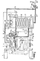
Le procédé de l'invention est avantageusement mis en oeuvre dans une installation du type représenté sur la figure du dessin annexé, les températures et pressions indiquées sont représentatives du "Fréon 12".The process of the invention is advantageously implemented in an installation of the type shown in the figure of the appended drawing, the temperatures and pressures indicated are representative of "Freon 12".
L'installation comprend essentiellement deux échangeurs froids; un échangeur refroidisseur en amont du saturateur et un échangeur-régulateur interne au saturateur.The installation essentially comprises two cold exchangers; a cooling exchanger upstream of the saturator and an internal exchanger-regulator in the saturator.
Le "Fréon" est stocké, en vrac à température ambiante, dans le réservoir de stockage (1), il traverse une pompe (2) avec clapet à décharge sous 15 bars, il est ensuite repris par la pompe-de surpression (3) double effet à piston. Cette pompe peut fonctionner en débitant 500 kg/heure, soit 375 litres/heure de "Fréson 12" (densité F 12 = 1,32 à 20°C), avec une pression de refoulement de 40 bars.The "Freon" is stored, in bulk at room temperature, in the storage tank (1), it passes through a pump (2) with relief valve under 15 bars, it is then taken up by the booster pump (3) double piston effect. This pump can operate by delivering 500 kg / hour, or 375 liters / hour of "Fréson 12" (density F 12 = 1.32 at 20 ° C), with a discharge pressure of 40 bar.
Le ."Fréon" comprimé est sous-refroidi dans l'échangeur froid dit échangeur refroidisseur (5) sur la canalisation d'arrivée dn "Fréon" (4). La température d'entrée varie entre - 10° C et + 50° C, et la température de sortie minimale est de - 10°C ; le débit instantané étant de 500 kg/heure. L'échangeur froid sur canalisation baigne dans un bain thermostaté (6) d'un groupe frigorifique (7) pouvant abaisser la température jusqu'à - 10°C. La température du bain thermostaté est contrôlée et régulée par l'intermédiaire du régulateur de température (8).The compressed "Freon" is sub-cooled in the cold exchanger called the cooler exchanger (5) on the inlet pipe to "Freon" (4). The inlet temperature varies between - 10 ° C and + 50 ° C, and the minimum outlet temperature is - 10 ° C; the instantaneous flow being 500 kg / hour. The cold exchanger on the pipe is bathed in a thermostatically controlled bath (6) of a refrigeration unit (7) which can lower the temperature down to - 10 ° C. The temperature of the thermostatically controlled bath is controlled and regulated by means of the temperature regulator (8).
Le "Fréon" sous-refroidi circule à l'intérieur de la canalisation calorifugée (9), traverse la vanne (10) commandée par le régulateur de niveau (11), de l'hydrocarbure liquide dans la zone de dissolution, puis toujours sous canalisation calorifugée est acheminé vers la buse de pulvérisation (12 A), située à la partie supérieure du saturateur (13). Cette buse de pulvérisation peut être de tout type convenable, tel du type tourbillonnaire à cône plein et à impact de diamètre de 15 à 50 cm, d'un débit élevé de 500 kg/heure sous une pression différentielle de 10 bars.The sub-cooled "Freon" circulates inside the insulated pipe (9), crosses the valve (10) controlled by the level regulator (11), liquid hydrocarbon in the dissolution zone, then always under insulated pipe is routed to the spray nozzle (12 A), located at the top of the saturator (13). This spray nozzle can be of any suitable type, such as the swirl type with full cone and impact diameter of 15 to 50 cm, with a high flow rate of 500 kg / hour under a differential pressure of 10 bars.
Le "Fréon" recyclé est recomprimé dans la pompe de recyclage (14) donnant une pression différentielle de 10 bars et un débit de 500 kg/heure, puis il est remonté dans la canalisation calorifugée (15) vers la buse de pulvérisation (12B) du même type que la buse de pulvérisation (12 A) et également située à la partie supérieure du corps du saturateur (13).The recycled "Freon" is recompressed in the recycling pump (14) giving a differential pressure of 10 bars and a flow rate of 500 kg / hour, then it is reassembled in the heat-insulated pipe (15) towards the spray nozzle (12B) of the same type as the spray nozzle (12 A) and also located at the upper part of the saturator body (13).
La corps du saturateur (13) dont le volume est fonction du débit désiré, peut être de forme cylindrique, par exemple de hauteur 2 mètres et diamètre 200 millimètres, résistant à une pression d'épreuve de 50 bars. Le saturateur est: muni des moyens de contrôle de pression par l'intermédiaire du manomètre de visualisation et pressostat d'alarme basse et haute pression (16) et de la vanne de purge et soupape de sécurité (17), tarée à 35 bars, situés l'un et l'autre à la partie supérieure du saturateur (13). Il est également muni des moyens de contrôle de la température du liquide du saturateur, par l'intermédiaire de la sonde de température (18) ; ainsi que des moyens de contrôle et régulation du niveau du "Fréon", dans le saturateur, par l'intermédiaire du régulateur-de niveau(11) . Le saturateur est entouré par le calorifugeage (13a).The saturator body (13), the volume of which is a function of the desired flow rate, can be of cylindrical shape, for example 2 meters high and 200 millimeters in diameter, resistant to a test pressure of 50 bars. The saturator is: fitted with pressure control means via the display manometer and low and high pressure alarm pressure switch (16) and the purge valve and safety valve (17), calibrated at 35 bars, both located at the top of the saturator (13). It is also provided with means for controlling the temperature of the liquid in the saturator, by means of the temperature probe (18); as well as means for controlling and regulating the level of the "Freon", in the saturator, by means of the level regulator (11). The saturator is surrounded by thermal insulation (13a).
L'anhydride carbonique est stocké en vrac dans le réservoir de stockage hante pression (19), maintenu sous 40 bars au minimum. 0°C la pression est de 40 bars, à-5°C elle se situe à 30 bars, il est donc prévu un réchauffage par température négative en hiver, par l'intermédiaire de l'épingle chauffante (20). L'anhydride carbonique délivré sous une pression d'au moins 40 bars passe à travers le réchauffeur anti-givrage (21) du détendeur C02 (22). La pression de l'anhydride carbonique en amont du détendeur est au moins de 40 bars et en aval de 30 bars ± 0,5 bar, le détendeur (22) fonctionne à débit instantané de 120 kg/heure (60 m3/heure). L'anhydride carbonique circule dans la canalisation (23), munie d'un clapet anti-retour ou d'un point haut anti-siphon, figuré en (24), les deux moyens pouvant âtre associés. Cette canalisation (24) pénètre à la partie inférieure du corps du saturateur (13) où elle se prolonge par une rampe perforée (25)destinée au débullage sous-pression de l'anhydride carbonique dans le "Fréon" liquide (26). La température de la solution de "Fréon" contenant du C02 est de + 10°C. Catte solution à forte concentration en C02 dissous est soutirée par la canalisation calorifugée (27), à la la partie inférieure du saturateur (13). Une fraction de cette solution saturée en CO2 est prélevée vers le recyclage via la pompe (14), et l'autre fraction destinée à l'utilisation est comprimée par les deux pompes de reprise en parallèle (28A) et (283), ayant chacune un débit minimum de 150 kg/heure, sous une pression élevée de refoulement, ajustée selon la demande de l'utilisateur par exemple de 150 bars, et sur la conduite d'utilisation (30), véhiculant le mélange vers l'utilisation maintenant le CO2 en phase dissoute, on a intercalé un accumulateur anti-coup de bélier (29).The carbon dioxide is stored in bulk in the haunted pressure storage tank (19), maintained at a minimum of 40 bars. 0 ° C the pressure is 40 bars, at -5 ° C it is located at 30 bars, it is therefore planned to reheat by negative temperature in winter, by means of the heating pin (20). The carbon dioxide delivered under a pressure of at least 40 bars passes through the anti-icing heater (21) of the C0 2 regulator (22). The carbon dioxide pressure upstream of the regulator is at least 40 bars and downstream of 30 bars ± 0.5 bar, the regulator (22) operates at an instantaneous flow rate of 120 kg / hour (60 m3 / hour). Carbon dioxide circulates in line (23), fitted with a non-return valve or a high anti-siphon point, shown in (24), the two means being able to be associated. This pipe (24) penetrates to the lower part of the saturator body (13) where it is extended by a perforated ramp (25) intended for the boiling under pressure of carbon dioxide in the liquid "Freon" (26). The temperature of the "Freon" solution containing C0 2 is + 10 ° C. This solution with a high concentration of dissolved C0 2 is drawn off by the heat-insulated pipe (27), at the bottom of the saturator (13). A fraction of this saturated CO 2 solution is taken for recycling via the pump (14), and the other fraction intended for use is compressed by the two parallel recovery pumps (28A) and (283), having each a minimum flow rate of 150 kg / hour, under a high discharge pressure, adjusted according to user demand for example 150 bars, and on the use line (30), conveying the mixture to use now CO 2 in dissolved phase, an anti-water hammer accumulator (29) was inserted.
Le saturateur est en outre équipé d'un échangeur interne dit échangeur+régulateur (31) en vue de compenser la réaction exothermique de dissolution du C02 dans le "Fréon" ; Cet échangeur interne étant situé pour sa partie inférieure au-dessus de la rampe de débullage du C02 (25) et pour sa partie supérieure en dessous du niveau liquide maintenu par le régulateur (11).The saturator is also equipped with an internal exchanger known as an exchanger + regulator (31) in order to compensate for the exothermic reaction of dissolution of C0 2 in the "Freon"; This internal exchanger being located for its lower part above the ramp for boiling the C0 2 (25) and for its upper part below the liquid level maintained by the regulator (11).
L'échange calorifique se fait par l'intermédiaire du fluide caloporteur constituant le bain thermostaté (6), maintenu à - 10°C par le groupe frigorifique (7). Le courant de fluide caloporteur circulant en circuit fermé calorifugé entre le groupe frigorifique et le saturateur, quitte le bain thermostaté par la canalisation (32) calc- rifugée jusqu'à son raccordement à la partie inférieure de l'échangeur interne (31) situé au-dessus de la rampe de débullage du CO, (25). Après un échange calorifique dans le sens ascendant, le fluide caloporteur après circulation dans la conduite (33), passage dans le système vanne-triple (34) est relancé par les pompes de circulation (35A) et (35B) en vue de son recyclage par la canalisation calorifugée (36) au bain thermostaté (6). Le débit de circulation du fluide caloporteur à l'intérieur de l'échangeur interne (31) est régulé par la température du milieu liquide dans le saturateur, indiquée par la sonde de température (18) et au moyen du régulateur (37) .The heat exchange takes place via the heat transfer fluid constituting the thermostatically controlled bath (6), maintained at -10 ° C by the refrigeration unit (7). The current of heat transfer fluid circulating in a closed circuit insulated between the refrigeration unit and the saturator, leaves the thermostated bath through the calcified pipe (32) until it is connected to the lower part of the internal exchanger (31) located at -above the CO bubble, (25). After a heat exchange in the upward direction, the heat transfer fluid after circulation in the line (33), passage in the valve-triple system (34) is restarted by the circulation pumps (35A) and (35B) for recycling by the thermally insulated pipe (36) to the thermostatically controlled bath (6). The circulation rate of the heat transfer fluid inside the internal exchanger (31) is regulated by the temperature of the liquid medium in the saturator, indicated by the temperature probe (18) and by means of the regulator (37).
Claims (10)
Priority Applications (1)
| Application Number | Priority Date | Filing Date | Title |
|---|---|---|---|
| AT85400353T ATE29678T1 (en) | 1984-02-29 | 1985-02-26 | METHOD AND EQUIPMENT FOR PREPARING SOLUTIONS WITH A HIGH PERCENTAGE OF DISSOLVED GAS; SO OBTAINED SOLUTIONS. |
Applications Claiming Priority (2)
| Application Number | Priority Date | Filing Date | Title |
|---|---|---|---|
| FR8403130 | 1984-02-29 | ||
| FR8403130A FR2560064A1 (en) | 1984-02-29 | 1984-02-29 | PROCESS FOR OBTAINING SOLUTIONS WITH HIGH GAS CONTENT, SOLUTIONS OBTAINED AND INSTALLATION FOR IMPLEMENTATION |
Publications (2)
| Publication Number | Publication Date |
|---|---|
| EP0155876A1 true EP0155876A1 (en) | 1985-09-25 |
| EP0155876B1 EP0155876B1 (en) | 1987-09-16 |
Family
ID=9301534
Family Applications (1)
| Application Number | Title | Priority Date | Filing Date |
|---|---|---|---|
| EP85400353A Expired EP0155876B1 (en) | 1984-02-29 | 1985-02-26 | Method and installation for obtaining solutions with a high percentage of dissolved gas; solutions obtained |
Country Status (9)
| Country | Link |
|---|---|
| US (1) | US4626376A (en) |
| EP (1) | EP0155876B1 (en) |
| JP (1) | JPS60210693A (en) |
| AT (1) | ATE29678T1 (en) |
| AU (1) | AU573490B2 (en) |
| CA (1) | CA1270745A (en) |
| DE (1) | DE3560616D1 (en) |
| ES (1) | ES8604236A1 (en) |
| FR (1) | FR2560064A1 (en) |
Cited By (3)
| Publication number | Priority date | Publication date | Assignee | Title |
|---|---|---|---|---|
| FR2642986A1 (en) * | 1989-02-15 | 1990-08-17 | Carboxyque Francaise | Process and plant for producing a mixture of "freon" and carbon dioxide |
| FR2651151A1 (en) * | 1989-02-15 | 1991-03-01 | Carboxyque Francaise | Process for the development and storage of a mixture of freon and carbon dioxide |
| WO1996014354A3 (en) * | 1994-11-02 | 1997-02-13 | Solvay Fluor & Derivate | Foaming agents containing liquid carbon dioxide |
Families Citing this family (7)
| Publication number | Priority date | Publication date | Assignee | Title |
|---|---|---|---|---|
| JPH0611512B2 (en) * | 1986-06-19 | 1994-02-16 | 三井東圧化学株式会社 | Method and apparatus for continuously producing foam sheet |
| US5112525A (en) * | 1987-12-10 | 1992-05-12 | Colgate-Palmolive Company | Method for making a post-foaming gel |
| DE19754686A1 (en) * | 1997-12-10 | 1999-06-17 | Messer Griesheim Gmbh | Method and device for introducing gas into a liquid |
| US6135433A (en) * | 1998-02-27 | 2000-10-24 | Air Liquide America Corporation | Continuous gas saturation system and method |
| GB2541753A (en) * | 2015-08-25 | 2017-03-01 | Linde Ag | A method of cryogenic chilling or cryogenic freezing of a product |
| CN112850973B (en) * | 2021-03-05 | 2024-08-20 | 郑州大学 | Modularized multi-stage area mineralization metallurgy system and treatment method |
| CN117983027B (en) * | 2024-04-03 | 2024-06-11 | 潍坊欣泽希化工有限公司 | Dynamic absorption device for hydrogen bromide acetic acid solution production and control method thereof |
Citations (5)
| Publication number | Priority date | Publication date | Assignee | Title |
|---|---|---|---|---|
| US2514463A (en) * | 1948-10-25 | 1950-07-11 | Jr George W Bayers | Liquid carbonator |
| US3342672A (en) * | 1964-05-07 | 1967-09-19 | Air Reduction | Combination propellant system using nitrous oxide |
| US3387425A (en) * | 1964-12-08 | 1968-06-11 | Allied Chem | Process for preparing aerosol packages |
| FR2154959A5 (en) * | 1971-10-01 | 1973-05-18 | Air Liquide | Aerosol propellant foam - contains nitrous oxide dissolved in polyalcohol solvent |
| FR2227896A2 (en) * | 1972-05-26 | 1974-11-29 | Anhydride Carbonique Ind |
Family Cites Families (5)
| Publication number | Priority date | Publication date | Assignee | Title |
|---|---|---|---|---|
| US2070167A (en) * | 1932-09-23 | 1937-02-09 | Iddings Carl | Method of making liquid sprays |
| US2242429A (en) * | 1937-07-27 | 1941-05-20 | California Packing Corp | Plant treatment |
| US2668419A (en) * | 1951-10-26 | 1954-02-09 | Specialties Dev Corp | Fluid carbon dioxide composition |
| US2964165A (en) * | 1956-11-13 | 1960-12-13 | Chempel Inc | Corrosion resistant aerosol package containing hydrolyzable material |
| DE2327067B2 (en) * | 1973-05-26 | 1977-01-13 | Hans Schwarzkopf Gmbh, 2000 Hamburg | AEROSOL |
-
1984
- 1984-02-29 FR FR8403130A patent/FR2560064A1/en active Pending
-
1985
- 1985-02-21 US US06/703,752 patent/US4626376A/en not_active Expired - Fee Related
- 1985-02-22 AU AU39084/85A patent/AU573490B2/en not_active Ceased
- 1985-02-26 DE DE8585400353T patent/DE3560616D1/en not_active Expired
- 1985-02-26 EP EP85400353A patent/EP0155876B1/en not_active Expired
- 1985-02-26 AT AT85400353T patent/ATE29678T1/en active
- 1985-02-27 ES ES540730A patent/ES8604236A1/en not_active Expired
- 1985-02-28 JP JP60037726A patent/JPS60210693A/en active Pending
- 1985-02-28 CA CA000475482A patent/CA1270745A/en not_active Expired - Lifetime
Patent Citations (5)
| Publication number | Priority date | Publication date | Assignee | Title |
|---|---|---|---|---|
| US2514463A (en) * | 1948-10-25 | 1950-07-11 | Jr George W Bayers | Liquid carbonator |
| US3342672A (en) * | 1964-05-07 | 1967-09-19 | Air Reduction | Combination propellant system using nitrous oxide |
| US3387425A (en) * | 1964-12-08 | 1968-06-11 | Allied Chem | Process for preparing aerosol packages |
| FR2154959A5 (en) * | 1971-10-01 | 1973-05-18 | Air Liquide | Aerosol propellant foam - contains nitrous oxide dissolved in polyalcohol solvent |
| FR2227896A2 (en) * | 1972-05-26 | 1974-11-29 | Anhydride Carbonique Ind |
Cited By (4)
| Publication number | Priority date | Publication date | Assignee | Title |
|---|---|---|---|---|
| FR2642986A1 (en) * | 1989-02-15 | 1990-08-17 | Carboxyque Francaise | Process and plant for producing a mixture of "freon" and carbon dioxide |
| FR2651151A1 (en) * | 1989-02-15 | 1991-03-01 | Carboxyque Francaise | Process for the development and storage of a mixture of freon and carbon dioxide |
| WO1996014354A3 (en) * | 1994-11-02 | 1997-02-13 | Solvay Fluor & Derivate | Foaming agents containing liquid carbon dioxide |
| US6303667B1 (en) | 1994-11-02 | 2001-10-16 | Solvay Fluor Und Derivate | Foaming agents containing liquid carbon dioxide |
Also Published As
| Publication number | Publication date |
|---|---|
| DE3560616D1 (en) | 1987-10-22 |
| US4626376A (en) | 1986-12-02 |
| FR2560064A1 (en) | 1985-08-30 |
| ES540730A0 (en) | 1986-01-16 |
| JPS60210693A (en) | 1985-10-23 |
| EP0155876B1 (en) | 1987-09-16 |
| AU3908485A (en) | 1985-09-05 |
| ATE29678T1 (en) | 1987-10-15 |
| ES8604236A1 (en) | 1986-01-16 |
| AU573490B2 (en) | 1988-06-09 |
| CA1270745A (en) | 1990-06-26 |
Similar Documents
| Publication | Publication Date | Title |
|---|---|---|
| EP0155876B1 (en) | Method and installation for obtaining solutions with a high percentage of dissolved gas; solutions obtained | |
| US4931225A (en) | Method and apparatus for dispersing a gas into a liquid | |
| CN207186963U (en) | Foam-generating device and foam fire-fighting equipment | |
| EP0691155B1 (en) | Method for gas deacidification in order to produce concentrated acid gases | |
| US7597115B2 (en) | Method and arrangement at a loading column | |
| RU2721211C2 (en) | Method and system for treatment of fluid extracted from well | |
| JP2004075771A (en) | Apparatus for producing gas hydrate | |
| US20140151050A1 (en) | Injection System for Enhanced Oil Recovery | |
| WO1998057106A1 (en) | Method and installation for cooling the contents of a chamber | |
| FR2466272A1 (en) | METHOD AND DEVICE FOR ENRICHING GAS LIQUIDS | |
| Zhu et al. | Dynamic behaviors of in-tank subcooled liquid with depressurization-induced phase change and the impact on primary breakup of flashing jet | |
| FR3072583B1 (en) | DEVICE FOR SUPERCRITICAL GASIFICATION OF AQUEOUS EFFLUENT | |
| EP0229434B1 (en) | Process for the improvement of the conditioning of gasification agents utilized in an underground coal-gasification process | |
| JP2002356685A (en) | Gas hydrate production method and production apparatus | |
| US20150217224A1 (en) | Method and system for producing pipeline quality natural gas | |
| FR2661450A1 (en) | Method and device for breaking up foam loaded with debris coming from drilling a well and for recovering the liquid phase from this foam | |
| JP4925348B2 (en) | Method and apparatus for producing gas hydrate | |
| FR2608438A1 (en) | Device for firefighting | |
| FR2715581A1 (en) | High efficiency pressurised gas in liq. dissolver | |
| CN1672782A (en) | Efficient gas hydrate preparing method and apparatus | |
| CH628678A5 (en) | FERMENTATION APPARATUS. | |
| RU2018331C1 (en) | Method for supply of liquid nitrogen to fire-hose barrel and device for its realization | |
| JP2005263825A (en) | Gas hydrate manufacturing method and manufacturing apparatus | |
| US20070035048A1 (en) | Method and equipment for mixing fluids | |
| DE102009015199A1 (en) | Producing fine gas hydrate in a spray reactor with an injection- and mixing system, comprises relaxing the supply of the hydrate forming gases and fluids from high to low pressure, which is carried out via concentric constructed nozzle |
Legal Events
| Date | Code | Title | Description |
|---|---|---|---|
| PUAI | Public reference made under article 153(3) epc to a published international application that has entered the european phase |
Free format text: ORIGINAL CODE: 0009012 |
|
| 17P | Request for examination filed |
Effective date: 19850301 |
|
| AK | Designated contracting states |
Designated state(s): AT BE CH DE FR GB IT LI LU NL SE |
|
| 17Q | First examination report despatched |
Effective date: 19860515 |
|
| ITF | It: translation for a ep patent filed | ||
| GRAA | (expected) grant |
Free format text: ORIGINAL CODE: 0009210 |
|
| AK | Designated contracting states |
Kind code of ref document: B1 Designated state(s): AT BE CH DE FR GB IT LI LU NL SE |
|
| PG25 | Lapsed in a contracting state [announced via postgrant information from national office to epo] |
Ref country code: AT Effective date: 19870916 |
|
| REF | Corresponds to: |
Ref document number: 29678 Country of ref document: AT Date of ref document: 19871015 Kind code of ref document: T |
|
| REF | Corresponds to: |
Ref document number: 3560616 Country of ref document: DE Date of ref document: 19871022 |
|
| GBT | Gb: translation of ep patent filed (gb section 77(6)(a)/1977) | ||
| PLBE | No opposition filed within time limit |
Free format text: ORIGINAL CODE: 0009261 |
|
| STAA | Information on the status of an ep patent application or granted ep patent |
Free format text: STATUS: NO OPPOSITION FILED WITHIN TIME LIMIT |
|
| 26N | No opposition filed | ||
| ITTA | It: last paid annual fee | ||
| EPTA | Lu: last paid annual fee | ||
| EAL | Se: european patent in force in sweden |
Ref document number: 85400353.0 |
|
| PGFP | Annual fee paid to national office [announced via postgrant information from national office to epo] |
Ref country code: FR Payment date: 19970113 Year of fee payment: 13 |
|
| PGFP | Annual fee paid to national office [announced via postgrant information from national office to epo] |
Ref country code: SE Payment date: 19970120 Year of fee payment: 13 |
|
| PGFP | Annual fee paid to national office [announced via postgrant information from national office to epo] |
Ref country code: GB Payment date: 19970122 Year of fee payment: 13 Ref country code: DE Payment date: 19970122 Year of fee payment: 13 |
|
| PGFP | Annual fee paid to national office [announced via postgrant information from national office to epo] |
Ref country code: NL Payment date: 19970123 Year of fee payment: 13 |
|
| PGFP | Annual fee paid to national office [announced via postgrant information from national office to epo] |
Ref country code: BE Payment date: 19970127 Year of fee payment: 13 |
|
| PGFP | Annual fee paid to national office [announced via postgrant information from national office to epo] |
Ref country code: CH Payment date: 19970129 Year of fee payment: 13 |
|
| PGFP | Annual fee paid to national office [announced via postgrant information from national office to epo] |
Ref country code: LU Payment date: 19970219 Year of fee payment: 13 |
|
| PG25 | Lapsed in a contracting state [announced via postgrant information from national office to epo] |
Ref country code: LU Free format text: LAPSE BECAUSE OF NON-PAYMENT OF DUE FEES Effective date: 19980226 Ref country code: GB Free format text: LAPSE BECAUSE OF NON-PAYMENT OF DUE FEES Effective date: 19980226 |
|
| PG25 | Lapsed in a contracting state [announced via postgrant information from national office to epo] |
Ref country code: SE Free format text: LAPSE BECAUSE OF NON-PAYMENT OF DUE FEES Effective date: 19980227 |
|
| PG25 | Lapsed in a contracting state [announced via postgrant information from national office to epo] |
Ref country code: LI Free format text: LAPSE BECAUSE OF NON-PAYMENT OF DUE FEES Effective date: 19980228 Ref country code: FR Free format text: THE PATENT HAS BEEN ANNULLED BY A DECISION OF A NATIONAL AUTHORITY Effective date: 19980228 Ref country code: CH Free format text: LAPSE BECAUSE OF NON-PAYMENT OF DUE FEES Effective date: 19980228 Ref country code: BE Free format text: LAPSE BECAUSE OF NON-PAYMENT OF DUE FEES Effective date: 19980228 |
|
| BERE | Be: lapsed |
Owner name: L' AIR LIQUIDE S.A. POUR L'ETUDE ET L'EXPLOITATION Effective date: 19980228 |
|
| PG25 | Lapsed in a contracting state [announced via postgrant information from national office to epo] |
Ref country code: NL Free format text: LAPSE BECAUSE OF NON-PAYMENT OF DUE FEES Effective date: 19980901 |
|
| GBPC | Gb: european patent ceased through non-payment of renewal fee |
Effective date: 19980226 |
|
| REG | Reference to a national code |
Ref country code: CH Ref legal event code: PL |
|
| EUG | Se: european patent has lapsed |
Ref document number: 85400353.0 |
|
| NLV4 | Nl: lapsed or anulled due to non-payment of the annual fee |
Effective date: 19980901 |
|
| PG25 | Lapsed in a contracting state [announced via postgrant information from national office to epo] |
Ref country code: DE Free format text: LAPSE BECAUSE OF NON-PAYMENT OF DUE FEES Effective date: 19981103 |
|
| REG | Reference to a national code |
Ref country code: FR Ref legal event code: ST |