EP0155877B1 - Elektrodynamische Vernier-Maschine - Google Patents
Elektrodynamische Vernier-Maschine Download PDFInfo
- Publication number
- EP0155877B1 EP0155877B1 EP85400358A EP85400358A EP0155877B1 EP 0155877 B1 EP0155877 B1 EP 0155877B1 EP 85400358 A EP85400358 A EP 85400358A EP 85400358 A EP85400358 A EP 85400358A EP 0155877 B1 EP0155877 B1 EP 0155877B1
- Authority
- EP
- European Patent Office
- Prior art keywords
- frame
- axis
- magnetic
- stator
- disposed
- Prior art date
- Legal status (The legal status is an assumption and is not a legal conclusion. Google has not performed a legal analysis and makes no representation as to the accuracy of the status listed.)
- Expired
Links
- 230000005520 electrodynamics Effects 0.000 title claims description 11
- 238000004804 winding Methods 0.000 claims description 30
- 230000004907 flux Effects 0.000 claims description 25
- 238000006073 displacement reaction Methods 0.000 claims description 2
- 230000002452 interceptive effect Effects 0.000 claims description 2
- 239000003638 chemical reducing agent Substances 0.000 description 5
- 230000001360 synchronised effect Effects 0.000 description 4
- XEEYBQQBJWHFJM-UHFFFAOYSA-N Iron Chemical compound [Fe] XEEYBQQBJWHFJM-UHFFFAOYSA-N 0.000 description 2
- 229910000831 Steel Inorganic materials 0.000 description 2
- 239000010959 steel Substances 0.000 description 2
- 230000000694 effects Effects 0.000 description 1
- 230000005284 excitation Effects 0.000 description 1
- 229910052742 iron Inorganic materials 0.000 description 1
- 239000000696 magnetic material Substances 0.000 description 1
- 230000005415 magnetization Effects 0.000 description 1
- 230000000737 periodic effect Effects 0.000 description 1
- 230000000135 prohibitive effect Effects 0.000 description 1
- 125000006850 spacer group Chemical group 0.000 description 1
- 238000005303 weighing Methods 0.000 description 1
Images




Classifications
-
- H—ELECTRICITY
- H02—GENERATION; CONVERSION OR DISTRIBUTION OF ELECTRIC POWER
- H02K—DYNAMO-ELECTRIC MACHINES
- H02K21/00—Synchronous motors having permanent magnets; Synchronous generators having permanent magnets
- H02K21/12—Synchronous motors having permanent magnets; Synchronous generators having permanent magnets with stationary armatures and rotating magnets
- H02K21/14—Synchronous motors having permanent magnets; Synchronous generators having permanent magnets with stationary armatures and rotating magnets with magnets rotating within the armatures
-
- H—ELECTRICITY
- H02—GENERATION; CONVERSION OR DISTRIBUTION OF ELECTRIC POWER
- H02K—DYNAMO-ELECTRIC MACHINES
- H02K1/00—Details of the magnetic circuit
- H02K1/06—Details of the magnetic circuit characterised by the shape, form or construction
- H02K1/22—Rotating parts of the magnetic circuit
- H02K1/27—Rotor cores with permanent magnets
- H02K1/2706—Inner rotors
- H02K1/272—Inner rotors the magnetisation axis of the magnets being perpendicular to the rotor axis
- H02K1/274—Inner rotors the magnetisation axis of the magnets being perpendicular to the rotor axis the rotor consisting of two or more circumferentially positioned magnets
- H02K1/2753—Inner rotors the magnetisation axis of the magnets being perpendicular to the rotor axis the rotor consisting of two or more circumferentially positioned magnets the rotor consisting of magnets or groups of magnets arranged with alternating polarity
-
- H—ELECTRICITY
- H02—GENERATION; CONVERSION OR DISTRIBUTION OF ELECTRIC POWER
- H02K—DYNAMO-ELECTRIC MACHINES
- H02K19/00—Synchronous motors or generators
- H02K19/02—Synchronous motors
- H02K19/10—Synchronous motors for multi-phase current
-
- H—ELECTRICITY
- H02—GENERATION; CONVERSION OR DISTRIBUTION OF ELECTRIC POWER
- H02K—DYNAMO-ELECTRIC MACHINES
- H02K19/00—Synchronous motors or generators
- H02K19/16—Synchronous generators
- H02K19/22—Synchronous generators having windings each turn of which co-operates alternately with poles of opposite polarity, e.g. heteropolar generators
-
- H—ELECTRICITY
- H02—GENERATION; CONVERSION OR DISTRIBUTION OF ELECTRIC POWER
- H02K—DYNAMO-ELECTRIC MACHINES
- H02K5/00—Casings; Enclosures; Supports
- H02K5/04—Casings or enclosures characterised by the shape, form or construction thereof
- H02K5/16—Means for supporting bearings, e.g. insulating supports or means for fitting bearings in the bearing-shields
- H02K5/173—Means for supporting bearings, e.g. insulating supports or means for fitting bearings in the bearing-shields using bearings with rolling contact, e.g. ball bearings
- H02K5/1735—Means for supporting bearings, e.g. insulating supports or means for fitting bearings in the bearing-shields using bearings with rolling contact, e.g. ball bearings radially supporting the rotary shaft at only one end of the rotor
Definitions
- the present invention relates to an electrodynamic vernier machine.
- An electrodynamic vernier machine is known, of the type comprising
- the first part being constituted by a magnetic armature comprising N teeth forming N notches, N being a whole number multiple of p, the notches opening into the air gap and being uniformly distributed along said direction,
- a rotary motor of this type comprises a rotor mounted for rotation about an axis, and a coaxial stator comprising N notches and N teeth. In the notches is arranged a polyphase winding creating a rotating field in the rotor.
- the M elements of the rotor are constituted by M teeth forming M notches, M being greater than N.
- a magnet is fixed coaxially in the rotor so as to create a continuous magnetic field which crosses the air gap and enters the stator.
- the known vernier electrodynamic machines are machines of the homopolar synchronous type, the two parts of which in relative motion respectively have two rows of teeth facing each other, the number of teeth in a row being different. the number of teeth in the other row.
- One such machine is described for example in German patent DE-C-92 958.
- the present invention aims to overcome these drawbacks.
- the M elements each comprise two flux generators oriented in alternating directions, these elements interfering with the N teeth of the first part to create in this first part a magnetic field with 2 poles, capable of clinging synchronously to the field sliding at 2 poles created by said means cooperating magnetically with the first part.
- the vernier motor represented in FIG. 1 comprises a stator 1 provided with a winding 2.
- the stator 1 is formed by an assembly of toothed magnetic sheets and the winding 2, of the polyphase type with 2 poles, is housed in the notches located between the stator teeth.
- the stator 1 is cylindrical in revolution around an axis 3 and of annular section.
- a toothed rotor 4 also formed from an assembly of magnetic sheets and mounted for rotation about the axis 3, is disposed in the internal cylindrical volume of the stator 1 and separated from the latter by a cylindrical air gap 5.
- a cylindrical magnet 6 is fixed coaxially in the rotor 4.
- the magnet 6 is fixed in the rotor 4 so that a flat face 7 of the magnet is located in the volume of the rotor 4 while its other flat face 8 is located outside this volume.
- the magnet 6 is magnetized in the direction 9 going from the face 8 to the face 7, so as to create in the rotor 4 a magnetic flux passing through the air gap 5 to penetrate into the stator 1.
- the latter is fixed to the inside a cylindrical magnetic carcass 10.
- the rotor 4 and the magnet 6 are fixed on a shaft 11 capable of turning around the axis 3 in two bearings mounted in flanges supported on the carcass 10.
- the flange 12 shown in section in FIG. 1 comprises a bearing 13 mounted on the shaft 11.
- the flange 12 is made of magnetic steel and has a surface 14 disposed near and facing the face 8 of the magnet 6 so as to close the circuit of the magnetic flux created by the magnet 6.
- the stator teeth 1 are evenly distributed around the axis of the machine.
- the stator has n not equal dental between them, by pair of poles defined by the winding 2.
- the teeth of the rotor are uniformly distributed around the axis, but the number of these teeth is more Student ; the rotor 4 comprises for example n + 1 teeth per pair of poles.
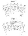
- the position of the rotor relative to the stator in the figure is such that one side of a tooth 15 of the rotor is aligned with one side of a tooth 16 of the stator in a radial direction 17. It can then be seen that the following teeth 18 , 19, 20 of the rotor are offset with respect to the homologous teeth 21, 22, 23 of the stator. These shifts cause a variation in the magnetic reluctance.
- the motor represented in FIGS. 1 and 2 is of the synchronous type and the configuration of the excitation poles rotates at a speed equal to the speed of rotation of the rotating field, while, as a result of the vernier effect, the speed of rotation of the rotor is equal to the quotient of the speed of the rotating field by a coefficient K.
- the offsets vary in stages along the air gap.
- each level corresponds substantially to a dental step.
- the bearings are of short length and the law of variation of the offset along the air gap is substantially linear.
- FIG. 3 shows a first stator group comprising the teeth 26, 27 and 28 and a second stator group comprising the teeth 29, 30 and 31. These two groups are separated from each other by a gap 32 in which is housed a bundle of the winding 33 of the stator.
- the teeth 26, 27 and 28 are just opposite the teeth 34, 35 and 36 of the rotor.
- the interval 32 is determined to obtain an offset such as 37 between the teeth 29, 30 and 31 of the stator and the teeth 38, 39 and 40 of the rotor.
- FIG. 4 represents the law of variation 41 of the magnetic shifts along the air gap in a machine of the type illustrated in FIG. 3.
- the position along the air gap is marked on the abscissa by an angle A relative to an axial reference plane, the offsets D being plotted on the ordinate.
- the curve 41 comprises successive stages 42, 43, 44 and 45. It is possible, from this law of variation by stages, to define a linear average law 46.
- the coefficient K is equal to the number of rotor notches per pair of poles of the stator winding insofar as the stator offset per pair of poles is one.
- vernier type electrodynamic machines also applies to vernier generators.
- the rotor of the machines shown in FIGS. 2 and 3 is turned and the electric current produced in the stator windings of these machines is collected.
- This principle also applies to vernier type linear machines in which the air gap is not arranged along a cylindrical surface, but along a flat surface separating the two parts in relative motion; the moving part then moves relative to the fixed part along a straight line parallel to the surface of the air gap.
- the known type of reduction gear shown in FIG. 5 comprises a first rotor 47 of annular shape. This rotor is not toothed but carries a continuous winding 48 with 2 poles.
- the reduction unit further comprises a second coaxial cylindrical rotor 49. This rotor has n + 1 teeth per pair of poles, not shown, similar to those of the motor rotor of FIG. 2.
- the stator 51 is separated from the rotors 47 and 49 by cylindrical air gaps 53 and 54.
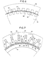
- FIG. 6 shows another vernier reducer of known type comprising a stator 55 and a rotor 56 coaxial and toothed.
- the rotating field is here produced by another coaxial rotor 57 disposed in the air gap located between the stator 55 and the rotor 56.
- the rotor 57 has 2 p magnets such as 58 juxtaposed along the air gap and whose radial magnetization directions 59 and 60 are alternated so as to create a rotating field with 2 poles. If the stator 55 has n notches per pair of poles and if the rotor 56 has n + 1 notches per pair of poles, the rotation of the rotor 57 at a speed v causes the rotor 56 to rotate at a speed .
- FIG. 7 represents a vernier electric motor according to the invention.
- This motor comprises a stator comprising a magnetic armature 61 formed of an assembly of magnetic sheets.
- This frame is cylindrical of revolution around an axis not shown, of annular cross section, and comprises teeth and notches opening onto the inner cylindrical surface of this frame.
- a 2-pole polyphase coil 63 is housed in the notches.
- a cylindrical rotor, of revolution around the axis and mounted in rotation around this axis, is arranged in the volume delimited by the internal cylindrical surface of the stator.
- the rotor comprises a cylindrical magnetic cylinder head 64, of annular shape, and substantially parallelepiped magnets such as 65 and 66 fixed on the external cylindrical surface of the cylinder head.
- the length of these magnets is parallel to the axis, this length being substantially equal to the length of iron of the stator armature.
- the width of the magnets is oriented tangentially with respect to the external cylindrical surface of the yoke 64, while their thickness is oriented radially.
- These magnets are juxtaposed on the external cylindrical surface of the cylinder head so that the external cylindrical surface of the rotor is separated from the internal cylindrical surface of the stator by a gap 67.
- the magnets are fixed together and on the cylinder head 64 example by collage. It is necessary to galvanically isolate the magnets from each other and from the yoke if they are conductive.
- the successive magnets along the air gap are magnetized radially so as to produce magnetic fluxes passing through the air gap in alternating directions such as 68, 69, 70 and 71.
- the rotor comprises, per pair of stator poles, a number m of pairs of magnets different from the number of n stator teeth per pair of poles. In the case of FIG. 7, the number m is equal to n + 1.
- Arrows such as 72, 73 and 74 have been drawn in the stator teeth to indicate the direction of the continuous magnetic flux coming from the magnets and passing through the stator.
- the length of each arrow is proportional to the intensity of the flow.
- the arrow 72 located in the tooth 75 corresponds to a maximum intensity of the flux, this being created by the magnet 65 magnetized in the direction 69 of the arrow 72, the axis of the tooth 75 passing through the middle of the width of the magnet.
- the arrow 74 located in tooth 76 corresponds to a lower flux intensity, since only part of the surface of tooth 76 facing the rotor covers the magnet 77 magnetized parallel to arrow 74, another part weaker of the tooth 76 covering the magnet 78 magnetized in the opposite direction to the arrow 74.
- the teeth 79 and 80 of the stator whose axes are located just at the junction between two magnets, receive no flux from the magnets of the rotor.
- the stator winding 63 creates in the rotor an alternating field with 2 poles which closes in the cylinder head 64.
- the machine shown in FIG. 7 is therefore a synchronous type motor. Given the difference between the number n of the stator teeth per pair of poles and the number (n + 1) of the pairs of magnets per pair of poles, carried by the rotor, this motor is of the vernier type when powered the stator winding 63 by a polyphase current, so as to create a field rotating around the axis, the rotor turns at a speed n + 1 times lower than that of the rotating field.
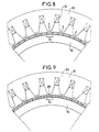
- the vernier electric motor shown in FIG. 8 comprises a stator and a rotor provided with a cylinder head 64; the stator and the cylinder head 64 are identical to the stator and the cylinder head of the engine illustrated in FIG. 7. But, in the case of FIG. 8, the rotor comprises electric coils such as 83 fixed on the external cylindrical surface of the cylinder head . These coils, in number equal to that of the magnets of the motor of FIG. 7, are arranged along the air gap so as to create fluxes passing through the air gap in alternate directions.
- the rotor then comprises a system of slip rings and brushes to supply these coils with direct current.
- the coils thus supplied play a role identical to that of the magnets in FIG. 7.
- the operation of the motor illustrated in FIG. 8 is therefore identical to that of the motor in FIG. 7.
- the vernier electric motor shown in FIG. 9 is similar to that of FIG. 8. However, the electric coils 84 forming part of the rotor of the motor in FIG. 9 include magnetic cores such as 85. These magnetic steel cores are arranged radially and are integral with the cylinder head 64.
- the vernier electric motor shown in FIG. 10 comprises a stator and a rotor provided with magnets 65, like the motor illustrated in FIG. 7. But in the case of FIG. 10, the cylinder head of the rotor is divided into two parts: a part 86 of small thickness, capable of supporting the magnets, and an internal coaxial part 87 separated from part 86 by an additional air gap. The internal part 87 is fixed; it closes the magnetic flux circuit. This arrangement results in a loss of ampere-turns in the additional air gap but has the advantage of reducing the inertia of the rotor.
- the vernier electric motor shown in FIG. 11 comprises a stator comprising an annular magnetic armature 88, cylindrical around an axis not shown.
- the frame 88 includes teeth and notches in which is disposed a polyphase winding 90 capable of creating a field with 2 poles rotating around the axis.
- the frame 88 has n teeth and n notches in pairs of poles, uniformly distributed around the axis.
- the inner cylindrical surface of the frame 88 is separated from a coaxial annular rotor by a gap 91 into which the notches of this frame open.
- the rotor comprises an annular magnetic chassis constituted for example by a bundle of sheets.
- This chassis comprises, by pair of stator poles, 2 (n + 1) radial sectors 92 between which magnets 93 are arranged; these sectors are uniformly distributed around the axis.
- the inner cylindrical surface of the rotor is separated, by another air gap 94, from another fixed, annular and coaxial magnetic armature 95.
- the frame 95 has n teeth per pair of poles, these teeth forming n notches opening into the air gap 94.
- the teeth of the frames 88 and 95 are arranged so that the axial plane of symmetry 96 of any tooth 97 of the the armature 95 coincides with the axial plane of symmetry of a notch 98 of the armature 88.
- the notches of the armature 95 contain a polyphase winding 99 capable of creating a rotating field identical to that created by the winding 90.
- the vernier electric motor shown in Figure 11 operates as follows.
- the magnets 93 are arranged so as to produce tangential magnetic fluxes alternately oriented in one direction and the other, as indicated by the arrows 100 to 103. These fluxes are concentrated in the radial sectors of the rotor which preferentially direct them alternately towards the armatures 88 or 95.
- a continuous 2-pole magnetic field is obtained, linked to the rotor. Due to the difference between the number of pairs of radial sectors of the rotor and that of the teeth of each frame, the speed of rotation of the rotor is n + 1 times lower than the speed of rotation of the rotating field created by the windings of the two stator armatures.
- the vernier electric motor represented in FIG. 12 comprises a stator comprising two toothed armatures 88 and 95 provided respectively with polyphase windings 90 and 99 with 2 poles, this stator being identical to that of the motor illustrated in FIG. 11. Each armature is therefore provided with n teeth by pairs of poles.
- the rotor of the motor in FIG. 12 comprises an annular magnetic chassis comprising 2 (n + 1) radial sectors 104 by pairs of poles, uniformly distributed around the axis. Between these sectors are arranged coils 106.
- the rotor also includes a set of brushes and rings not visible in the figure to supply these windings with direct current.
- the rotor is separated from the two stator armatures 88 and 95 respectively by two air gaps 107 and 108.
- the coils 106 are arranged so as to create between the radial sectors tangential magnetic fluxes 109 to 112 oriented in alternating directions. These flows are concentrated in the radial sectors which direct them alternately towards the armatures 88 and 95.
- the magnetic frame of the rotor also comprises tangential cores 113 connecting the radial sectors to each other.
- the coils 106 are wound around the tangential cores.
- vernier machines according to the invention described above with reference to FIGS. 7 to 12 are rotary motors with regular dental steps, it is also possible to produce machines according to the invention comprising groups of dental steps equal to each other and gradually shifted. It is also possible to produce machines according to the invention operating as generators, reducers, and electrodynamic machines operating by linear displacement.
- Vernier electrodynamic machines according to the invention are of the heteropolar type and have the advantage, compared to vernier machines according to the prior art, of having a smaller bulk and inertia.
- Vernier machines according to the present invention can be applied in particular in the field of robotics, to produce motors of low rotational speed and low inertia, and conversely to produce compact motors with very high torque.
Landscapes
- Engineering & Computer Science (AREA)
- Power Engineering (AREA)
- Linear Motors (AREA)
- Synchronous Machinery (AREA)
- Permanent Magnet Type Synchronous Machine (AREA)
- Iron Core Of Rotating Electric Machines (AREA)
Claims (11)
Applications Claiming Priority (2)
| Application Number | Priority Date | Filing Date | Title |
|---|---|---|---|
| FR8403154A FR2560461B1 (fr) | 1984-02-29 | 1984-02-29 | Machine electrodynamique vernier |
| FR8403154 | 1984-02-29 |
Publications (2)
| Publication Number | Publication Date |
|---|---|
| EP0155877A1 EP0155877A1 (de) | 1985-09-25 |
| EP0155877B1 true EP0155877B1 (de) | 1988-08-10 |
Family
ID=9301549
Family Applications (1)
| Application Number | Title | Priority Date | Filing Date |
|---|---|---|---|
| EP85400358A Expired EP0155877B1 (de) | 1984-02-29 | 1985-02-26 | Elektrodynamische Vernier-Maschine |
Country Status (7)
| Country | Link |
|---|---|
| US (1) | US4757220A (de) |
| EP (1) | EP0155877B1 (de) |
| JP (1) | JPS61500248A (de) |
| DE (1) | DE3564360D1 (de) |
| ES (1) | ES8606747A1 (de) |
| FR (1) | FR2560461B1 (de) |
| WO (1) | WO1985004058A1 (de) |
Families Citing this family (40)
| Publication number | Priority date | Publication date | Assignee | Title |
|---|---|---|---|---|
| FR2588132A1 (fr) * | 1985-09-27 | 1987-04-03 | Centre Nat Rech Scient | Machine synchrone polyentrefers a aimants permanents |
| DE3925959A1 (de) * | 1989-08-05 | 1991-02-14 | Stoeber Antriebstech Gmbh & Co | Synchronmotor, vorzugsweise elektronisch kommutierter, permanentmagneterregter servomotor |
| US5204569A (en) * | 1990-02-07 | 1993-04-20 | Asmo Co., Ltd. | Anisotropic magnet for rotary electric machine |
| US5081388A (en) * | 1990-07-24 | 1992-01-14 | Chen Shew Nen | Magnetic induction motor |
| US5289072A (en) * | 1990-11-23 | 1994-02-22 | J. M. Voith Gmbh | Electrical machine |
| DE69209187T2 (de) * | 1991-07-31 | 1996-08-14 | Mitsubishi Heavy Ind Ltd | Elektrischer Motor mit einem sphärischen Läufer und seine Anwendungsvorrichtung |
| JP3152405B2 (ja) * | 1992-06-10 | 2001-04-03 | オークマ株式会社 | 電動機 |
| US5910691A (en) * | 1995-03-20 | 1999-06-08 | Wavre; Nicolas | Permanent-magnet linear synchronous motor |
| FR2744855B1 (fr) * | 1996-02-14 | 1998-04-17 | Koehler Gerard | Machine dynamo-electrique a reluctance variable hybride a effet vernier et procede de fabrication et de calcul |
| SE9700477L (sv) * | 1997-02-12 | 1998-08-13 | Vilmos Toeroek | Elektrisk maskin |
| CN1225076C (zh) * | 1999-04-13 | 2005-10-26 | 松下电器产业株式会社 | 线性电动机以及具有线性电动机的压缩机 |
| DE10041329A1 (de) * | 2000-08-23 | 2002-03-14 | Siemens Ag | Permanentmagneterregter Läufer für einen permanentmagneterregten elektrischen Antrieb, insbesondere für AC-Hauptantriebe |
| US6930433B2 (en) * | 2003-04-16 | 2005-08-16 | Apex Drives Laboratories, Inc. | Brushless electro-mechanical device |
| US7863784B2 (en) * | 2005-08-15 | 2011-01-04 | Apex Drive Laboratories, Inc | Axial flux permanent magnet machines |
| DE10248771A1 (de) * | 2002-10-18 | 2004-04-29 | Siemens Ag | Permanenterregte Synchronmaschine |
| US7723888B2 (en) * | 2004-05-25 | 2010-05-25 | Marko Petek | Synchronous electromechanical transformer |
| US7230355B2 (en) * | 2004-12-21 | 2007-06-12 | Baldor Electric Company | Linear hybrid brushless servo motor |
| WO2007012370A1 (de) * | 2005-07-26 | 2007-02-01 | Ebm-Papst St. Georgen Gmbh & Co. Kg | Bürstenloser elektromotor |
| FR2912378B1 (fr) | 2007-02-14 | 2009-03-20 | Aircelle Sa | Nacelle de moteur a reaction pour un avion |
| US7566997B2 (en) * | 2007-03-30 | 2009-07-28 | Baldor Electric Company | Gas bearing system |
| FR2928052A1 (fr) * | 2008-01-04 | 2009-08-28 | Gerard Koehler | Stator d'une machine dynamo-electrique a reluctance variable, a phases angulairement reparties dans des secteurs et a effet vernier |
| RU2411623C2 (ru) * | 2008-02-11 | 2011-02-10 | Закрытое акционерное общество "Завод Сибирского Технологического Машиностроения" | Электрическая машина переменного тока |
| US8847464B2 (en) | 2008-06-12 | 2014-09-30 | General Electric Company | Electrical machine with improved stator flux pattern across a rotor that permits higher torque density |
| FR2945682B1 (fr) | 2009-05-18 | 2012-12-07 | Erneo | Machine vernier a aimants. |
| FR2945683B1 (fr) | 2009-05-18 | 2011-05-20 | Erneo | Machine vernier a aimants inseres. |
| DE102010017973A1 (de) | 2010-04-23 | 2011-10-27 | Thomas Magnete Gmbh | Transversalmotor mit hybridem Stator und Verfahren zur Herstellung der Statorbauteile |
| US8749104B2 (en) | 2010-04-30 | 2014-06-10 | Alstom Renewable Technologies | Rotating electric machine, especially synchronous permanent magnet machine |
| US20130270955A1 (en) * | 2010-10-08 | 2013-10-17 | Global Motors Invent Pty Ltd | Electromagnetic machine |
| RU2471279C1 (ru) * | 2011-04-28 | 2012-12-27 | Федеральное государственное бюджетное образовательное учреждение высшего профессионального образования "Казанский национальный исследовательский технический университет им. А.Н. Туполева-КАИ" (КНИТУ-КАИ) | Обмотка статора электрической машины |
| US8791608B2 (en) | 2011-07-11 | 2014-07-29 | Baldor Electric Company | Primary for linear drive motor with solid steel stacks |
| US8418350B2 (en) | 2011-07-11 | 2013-04-16 | Baldor Electric Company | Method of forming a secondary for linear drive motor comprising sheet of highly permeable magnetic material having synchronized motor teeth, encoder teeth, and commutation tracks integrally formed therein |
| US8803371B2 (en) | 2011-07-11 | 2014-08-12 | Baldor Electric Company | Secondary for linear drive motor comprising sheet of highly permeable magnetic material having synchronized motor teeth, encoder teeth, and commutation tracks integrally formed therein |
| US8922068B2 (en) | 2011-07-11 | 2014-12-30 | Baldor Electric Company | Linear drive motor with improved bearing system |
| AU348920S (en) * | 2013-03-22 | 2013-05-30 | Radial Flux Laboratories Pty Ltd | Electrical machine rotor lamination segment |
| DE102016203616A1 (de) | 2016-03-04 | 2017-09-07 | Lenze Drives Gmbh | Vernier-Außenläufermaschine und Motorsystem |
| FR3061613A1 (fr) * | 2017-01-02 | 2018-07-06 | Michael Nadreau | Machine electrique tournante de forme torique |
| DE102017207116A1 (de) * | 2017-04-27 | 2018-10-31 | Zf Friedrichshafen Ag | Wankstabilisator sowie Verwendung eines Wankstabilisators in einem Kraftfahrzeug |
| US11245317B2 (en) | 2019-12-05 | 2022-02-08 | Whirlpool Corporation | Direct drive electric motor having stator and magnet configurations for improved torque capability |
| CN113890220B (zh) * | 2021-08-19 | 2026-05-08 | 宁波恒帅股份有限公司 | 一种谐波磁场驱动电机 |
| CN114598082A (zh) * | 2022-03-05 | 2022-06-07 | 宁波恒帅股份有限公司 | 一种谐波磁场驱动电机 |
Family Cites Families (18)
| Publication number | Priority date | Publication date | Assignee | Title |
|---|---|---|---|---|
| DE92958C (de) * | ||||
| US1491441A (en) * | 1921-12-05 | 1924-04-22 | Gen Electric | High-speed alternating-current dynamo-electric machine |
| GB418659A (en) * | 1933-01-28 | 1934-10-29 | Gen Electric | Improvements in and relating to dynamo electric machines |
| FR848115A (fr) * | 1938-09-02 | 1939-10-24 | Magnetos Lucifer S A | Petit générateur magnéto-électrique avec induit à double prise de flux |
| DE971680C (de) * | 1952-12-20 | 1959-03-12 | Normalzeit G M B H | Wechselstrommaschine kleiner Leistung mit einem Dauermagneten |
| US2790098A (en) * | 1953-12-03 | 1957-04-23 | Nyyssonen Einard | Polyphase synchronous machine |
| US3001093A (en) * | 1956-08-30 | 1961-09-19 | North American Aviation Inc | Low speed synchronous motor |
| FR1149195A (fr) * | 1957-07-23 | 1957-12-20 | Hatot Leon Ets | Perfectionnements aux petites machines et aux instruments magnétoélectriques |
| US3303369A (en) * | 1963-12-18 | 1967-02-07 | Westinghouse Electric Corp | Dynamoelectric machines |
| DE1638361A1 (de) * | 1967-03-09 | 1970-05-21 | Licentia Gmbh | Mehrphasige elektrische Synchronmaschine |
| US4190779A (en) * | 1976-05-04 | 1980-02-26 | Ernest Schaeffer | Step motors |
| JPS5523711A (en) * | 1978-07-29 | 1980-02-20 | Sony Corp | Rotary electric machine |
| JPS598145B2 (ja) * | 1980-08-27 | 1984-02-23 | ブラザー工業株式会社 | Vr形リニアステップモ−タ |
| EP0094978B2 (de) * | 1982-05-24 | 1995-11-02 | Magnet-Motor Gesellschaft für magnetmotorische Technik mbH | Rotatorische, elektrische Maschine |
| DE3476497D1 (en) * | 1983-05-02 | 1989-03-02 | Weh Herbert | Electric drive |
| US4712028A (en) * | 1984-05-21 | 1987-12-08 | Sigma Instruments, Inc. | Magnetically assisted stepping motor |
| US4668883A (en) * | 1985-07-30 | 1987-05-26 | Shinko Electric Co., Ltd. | Linear pulse motor |
| US4675582A (en) * | 1985-12-24 | 1987-06-23 | E. I. Du Pont De Nemours And Company | System useful for controlling multiple synchronous secondaries of a linear motor along an elongated path |
-
1984
- 1984-02-29 FR FR8403154A patent/FR2560461B1/fr not_active Expired
-
1985
- 1985-02-26 WO PCT/FR1985/000033 patent/WO1985004058A1/fr not_active Ceased
- 1985-02-26 DE DE8585400358T patent/DE3564360D1/de not_active Expired
- 1985-02-26 US US06/797,378 patent/US4757220A/en not_active Expired - Lifetime
- 1985-02-26 JP JP60500926A patent/JPS61500248A/ja active Pending
- 1985-02-26 EP EP85400358A patent/EP0155877B1/de not_active Expired
- 1985-02-28 ES ES540798A patent/ES8606747A1/es not_active Expired
Also Published As
| Publication number | Publication date |
|---|---|
| EP0155877A1 (de) | 1985-09-25 |
| DE3564360D1 (en) | 1988-09-15 |
| ES8606747A1 (es) | 1986-04-16 |
| JPS61500248A (ja) | 1986-02-06 |
| ES540798A0 (es) | 1986-04-16 |
| FR2560461B1 (fr) | 1988-03-18 |
| US4757220A (en) | 1988-07-12 |
| FR2560461A1 (fr) | 1985-08-30 |
| WO1985004058A1 (fr) | 1985-09-12 |
Similar Documents
| Publication | Publication Date | Title |
|---|---|---|
| EP0155877A1 (de) | Elektrodynamische Vernier-Maschine | |
| EP0158935B1 (de) | Elekrodynamische Verniermaschine | |
| EP0909010B1 (de) | Elektrische Maschine mit Flussumschaltung, insbesondere Stromgenerator für Kraftfahrzeuge | |
| CA2482125C (fr) | Machine electrique a flux transverse a rotor dente | |
| FR2823614A1 (fr) | Machine tournante electrique comportant un stator forme de secteurs assembles | |
| CH653189A5 (fr) | Moteur pas a pas electrique. | |
| EP2102965A1 (de) | Elektrische rotationsmaschine, im besondern für den starter eines automobils | |
| EP2209192A1 (de) | Drehende elektrische Maschine, insbesondere für Kraftfahrzeuganlasser | |
| FR2744855A1 (fr) | Machine dynamo-electrique a reluctance variable hybride a effet vernier et procede de fabrication et de calcul | |
| FR2920259A1 (fr) | Machine electrique tournante, en particulier pour un demarreur automobile | |
| WO2021028760A1 (fr) | Système de vis-écrou magnétiques | |
| EP0312464B1 (de) | Elektrische Maschine insbesondere mit radialen Luftspalten | |
| FR2727174A1 (fr) | Palier magnetique a noyau de bobine rapporte | |
| EP0321332B1 (de) | Elektrischer Motor mit hohem Wirkungsgrad und schwacher Momentschwingung | |
| FR3083022A1 (fr) | Machine electrique tournante ayant une configuration de rotor reduisant les ondulations de couple | |
| EP1251023A1 (de) | Elektrische Maschine mit äusserem Läufer | |
| FR2945683A1 (fr) | Machine vernier a aimants insires. | |
| WO2014122374A1 (fr) | Moteur ou génératrice électromagnétique polyentrefers à aimants permanents et élément à bobinage sans fer | |
| EP1416618A1 (de) | Rotor für eine elektrische Drehmaschine mit Doppelerregung und entsprechende elektrische Maschine | |
| EP1069670A1 (de) | Hybrid-Elektromotor | |
| FR2802724A1 (fr) | Stator a dents convexes | |
| FR3086118A1 (fr) | Machine electrique tournante munie d'un rotor a masse reduite | |
| CH622914A5 (en) | Electric motor | |
| FR2915033A1 (fr) | Machine electrique tournante a fort couple et double stator | |
| FR2588131A1 (fr) | Machine electrique tournante a reluctance variable polyentrefers |
Legal Events
| Date | Code | Title | Description |
|---|---|---|---|
| PUAI | Public reference made under article 153(3) epc to a published international application that has entered the european phase |
Free format text: ORIGINAL CODE: 0009012 |
|
| AK | Designated contracting states |
Designated state(s): BE CH DE FR GB IT LI NL SE |
|
| RAP1 | Party data changed (applicant data changed or rights of an application transferred) |
Owner name: ALSTHOM |
|
| 17P | Request for examination filed |
Effective date: 19860325 |
|
| 17Q | First examination report despatched |
Effective date: 19870824 |
|
| GRAA | (expected) grant |
Free format text: ORIGINAL CODE: 0009210 |
|
| AK | Designated contracting states |
Kind code of ref document: B1 Designated state(s): BE CH DE FR GB IT LI NL SE |
|
| REF | Corresponds to: |
Ref document number: 3564360 Country of ref document: DE Date of ref document: 19880915 |
|
| ITF | It: translation for a ep patent filed | ||
| GBT | Gb: translation of ep patent filed (gb section 77(6)(a)/1977) | ||
| PLBE | No opposition filed within time limit |
Free format text: ORIGINAL CODE: 0009261 |
|
| STAA | Information on the status of an ep patent application or granted ep patent |
Free format text: STATUS: NO OPPOSITION FILED WITHIN TIME LIMIT |
|
| 26N | No opposition filed | ||
| ITTA | It: last paid annual fee | ||
| EAL | Se: european patent in force in sweden |
Ref document number: 85400358.9 |
|
| PGFP | Annual fee paid to national office [announced via postgrant information from national office to epo] |
Ref country code: SE Payment date: 19960129 Year of fee payment: 12 |
|
| PGFP | Annual fee paid to national office [announced via postgrant information from national office to epo] |
Ref country code: BE Payment date: 19960205 Year of fee payment: 12 |
|
| PG25 | Lapsed in a contracting state [announced via postgrant information from national office to epo] |
Ref country code: SE Effective date: 19970227 |
|
| PG25 | Lapsed in a contracting state [announced via postgrant information from national office to epo] |
Ref country code: BE Effective date: 19970228 |
|
| BERE | Be: lapsed |
Owner name: ALSTHOM Effective date: 19970228 |
|
| EUG | Se: european patent has lapsed |
Ref document number: 85400358.9 |
|
| REG | Reference to a national code |
Ref country code: CH Ref legal event code: NV Representative=s name: BOVARD AG PATENTANWAELTE Ref country code: CH Ref legal event code: PUE Owner name: ALSTHOM TRANSFER- KLEBER MOZART * GEC ALSTHOM SA - Ref country code: CH Ref legal event code: PFA Free format text: GEC ALSTHOM PARVEX SA TRANSFER- PARVEX * KLEBER MOZART TRANSFER- GEC ALSTHOM SA * KLEBER GIRAUDOUX -DANN IN- GEC ALSTHOM PARVEX SA |
|
| REG | Reference to a national code |
Ref country code: FR Ref legal event code: CD Ref country code: FR Ref legal event code: TP Ref country code: FR Ref legal event code: CA |
|
| NLS | Nl: assignments of ep-patents |
Owner name: KLEBER GIRAUDOUX;KLEBER MOZART |
|
| NLT1 | Nl: modifications of names registered in virtue of documents presented to the patent office pursuant to art. 16 a, paragraph 1 |
Owner name: PARVEX SA;GEC ALSTHOM PARVEX SA;GEC ALSTHOM SA |
|
| PGFP | Annual fee paid to national office [announced via postgrant information from national office to epo] |
Ref country code: GB Payment date: 20001208 Year of fee payment: 17 |
|
| PGFP | Annual fee paid to national office [announced via postgrant information from national office to epo] |
Ref country code: CH Payment date: 20010213 Year of fee payment: 17 |
|
| PGFP | Annual fee paid to national office [announced via postgrant information from national office to epo] |
Ref country code: FR Payment date: 20010227 Year of fee payment: 17 |
|
| PGFP | Annual fee paid to national office [announced via postgrant information from national office to epo] |
Ref country code: NL Payment date: 20010228 Year of fee payment: 17 |
|
| PGFP | Annual fee paid to national office [announced via postgrant information from national office to epo] |
Ref country code: DE Payment date: 20010306 Year of fee payment: 17 |
|
| REG | Reference to a national code |
Ref country code: GB Ref legal event code: IF02 |
|
| PG25 | Lapsed in a contracting state [announced via postgrant information from national office to epo] |
Ref country code: GB Free format text: LAPSE BECAUSE OF NON-PAYMENT OF DUE FEES Effective date: 20020226 |
|
| PG25 | Lapsed in a contracting state [announced via postgrant information from national office to epo] |
Ref country code: LI Free format text: LAPSE BECAUSE OF NON-PAYMENT OF DUE FEES Effective date: 20020228 Ref country code: CH Free format text: LAPSE BECAUSE OF NON-PAYMENT OF DUE FEES Effective date: 20020228 |
|
| PG25 | Lapsed in a contracting state [announced via postgrant information from national office to epo] |
Ref country code: NL Free format text: LAPSE BECAUSE OF NON-PAYMENT OF DUE FEES Effective date: 20020901 |
|
| PG25 | Lapsed in a contracting state [announced via postgrant information from national office to epo] |
Ref country code: DE Free format text: LAPSE BECAUSE OF NON-PAYMENT OF DUE FEES Effective date: 20020903 |
|
| REG | Reference to a national code |
Ref country code: CH Ref legal event code: PL |
|
| GBPC | Gb: european patent ceased through non-payment of renewal fee |
Effective date: 20020226 |
|
| PG25 | Lapsed in a contracting state [announced via postgrant information from national office to epo] |
Ref country code: FR Free format text: LAPSE BECAUSE OF NON-PAYMENT OF DUE FEES Effective date: 20021031 |
|
| NLV4 | Nl: lapsed or anulled due to non-payment of the annual fee |
Effective date: 20020901 |
|
| REG | Reference to a national code |
Ref country code: FR Ref legal event code: ST |