EP0155916A2 - Dispositif de transport et d'accumulation - Google Patents
Dispositif de transport et d'accumulation Download PDFInfo
- Publication number
- EP0155916A2 EP0155916A2 EP85830042A EP85830042A EP0155916A2 EP 0155916 A2 EP0155916 A2 EP 0155916A2 EP 85830042 A EP85830042 A EP 85830042A EP 85830042 A EP85830042 A EP 85830042A EP 0155916 A2 EP0155916 A2 EP 0155916A2
- Authority
- EP
- European Patent Office
- Prior art keywords
- pulleys
- pair
- signatures
- fact
- chains
- Prior art date
- Legal status (The legal status is an assumption and is not a legal conclusion. Google has not performed a legal analysis and makes no representation as to the accuracy of the status listed.)
- Granted
Links
Images
Classifications
-
- B—PERFORMING OPERATIONS; TRANSPORTING
- B65—CONVEYING; PACKING; STORING; HANDLING THIN OR FILAMENTARY MATERIAL
- B65H—HANDLING THIN OR FILAMENTARY MATERIAL, e.g. SHEETS, WEBS, CABLES
- B65H31/00—Pile receivers
- B65H31/30—Arrangements for removing completed piles
- B65H31/3072—Arrangements for removing completed piles by moving a surface supporting the pile of articles on edge, e.g. by using belts or carriages
-
- B—PERFORMING OPERATIONS; TRANSPORTING
- B42—BOOKBINDING; ALBUMS; FILES; SPECIAL PRINTED MATTER
- B42C—BOOKBINDING
- B42C19/00—Multi-step processes for making books
- B42C19/08—Conveying between operating stations in machines
-
- B—PERFORMING OPERATIONS; TRANSPORTING
- B65—CONVEYING; PACKING; STORING; HANDLING THIN OR FILAMENTARY MATERIAL
- B65H—HANDLING THIN OR FILAMENTARY MATERIAL, e.g. SHEETS, WEBS, CABLES
- B65H31/00—Pile receivers
- B65H31/04—Pile receivers with movable end support arranged to recede as pile accumulates
- B65H31/06—Pile receivers with movable end support arranged to recede as pile accumulates the articles being piled on edge
-
- B—PERFORMING OPERATIONS; TRANSPORTING
- B65—CONVEYING; PACKING; STORING; HANDLING THIN OR FILAMENTARY MATERIAL
- B65H—HANDLING THIN OR FILAMENTARY MATERIAL, e.g. SHEETS, WEBS, CABLES
- B65H2301/00—Handling processes for sheets or webs
- B65H2301/40—Type of handling process
- B65H2301/42—Piling, depiling, handling piles
- B65H2301/422—Handling piles, sets or stacks of articles
- B65H2301/4226—Delivering, advancing piles
- B65H2301/42265—Delivering, advancing piles by moving the surface supporting the pile of articles on edge, e.g. conveyor or carriage
Definitions
- the present invention relates generally to an accumulation/conveyor device, which is particularly, but not exclusively, adapted for conveying and/or accumulating stacks of signatures.
- the said packs of signatures are normally preliminarily pressed, and held between pairs of boards of wood and held by straps. Such packs of signatures must be maintained together and positioned sideways with the signatures vertical before the individual signatures are introduced into the various subsequent operating machines. In order to be able to obtain this result it is necessary to apply to the signatures a certain force in a direction such as to advance them for introduction into the subsequent operating machines without damage in any way to the sheets which, as mentioned above, must be disposed sideways.
- the individual signatures at the leading end of the stack must be unstressed so as to be able progressively to slip down to a horizontal position for th E purpose cf becoming spaced and then withdrawn one at a time without the risk of simultaneous introduction of more than one adjacent signature which might cause obstructions to the various operating machines downstream of the supply device.
- the present invention seeks therefore to provide an accumulation and conveyor device for the automatic accumulation and conveying of signatures to the subsequent working operations, which will be very simple and therefore inexpensive to produce and which will be economical to maintain.
- an accumulator conveyor device for simultaneously conveying and accumulating packs of signatures for feeding to a subsequent working stage, characterised by the fact that it comprises a support structure carrying at least a pair of shafts disposed horizontally and each provided with at least a pair of sprockets over which pass special conveyor chains constituted by articulated links pivotally connected by articulation pins, at least some of the articulation pins carrying a pair of pulleys, longitudinally adjacent pairs of pulleys being joined by loop members defining support surfaces for the packs of signatures.
- An advantage of the device of the present invention lies in the fact that it is highly reliable because the operating members are subjected to practically no wear, and are nevertheless able to cause the individual signature's advance in the conveying direction in an extremely delicate and certain manner at the correct feed speed for the subsequent machinery.
- the device of the present invention permits packs of signatures which have previously been pressed between pairs of boards and tied with straps, to be conveyed and at the same to be loosened on an extended support plane so that the individual signatures can become separated from one another to be removed from the conveyor one at a time.
- the various individual signatures after having been freed from the said preliminarily wrapped packs, are made to advance at a suitable speed by driving the special conveyor chains by conventional driving means.
- These chains have articulated links which can turn about suitable articulation pins, and at least some of the said links support pulleys or pairs of pulleys suitably spaced and disposed either on the same side or, alternatively, on opposite sides of the link of the chain on which they are carried.
- Each pulley is independently turnable on its pivot pin and longitudinally adjacent pulleys are joined in pairs by flexible belts, webs, wires, cables or chains turnable with the said pair of pulleys on which they are carried.
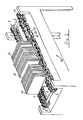
- the accumulator conveyor shown acts as an accumulation device for stacks of signatures and as a device for conveying such signatures towards the subsequent working operations.
- the device comprises a support frame carrying a pair of shafts 1 and 2, disposed horizontally and each supporting a pair of sprockets 3, 4 , and 5 , 6, over which pass special conveyor chains 7 and 8 made to advance at a suitable speed by driving members (not shown), of conventional type.
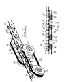
- the conveyor chains 7 and 8 are constituted by articulated links 9 pivotally connected by articulation pins 10.
- the articulated links 9 support, in their turn, pairs of pulleys 11 and 12 suitably spaced and disposed on the same side, or alternatively, on opposite sides with respect to the articulated links 9 of the chains 7 and 8.
- each pulley has a groove 18 and is independent in such a manner that, whenever a pulley turns in a sense opposite to that of advancement of a chain 7 and 8 by the effect of the accumulation of signatures 15 positioned downstream of the device 20, such rotation is not transmitted to the pulleys behind, enabling each pulley to turn entirely independently.
- Adjacent pairs of pulleys 11 and 12 are joined by a loop of flexible linear form, which may be a belt or a web or a wire or a cable or a chain 16 which can turn about the linked pair of pulleys and act to transmit movement to the overlying signatures in the direction of motion of the chain of links 9, 10 unless the signatures are subjected to a restraining force, in which case the chains 9, 10 can continue to turn whilst applying only a very gentle pressure to the signatures in the intended direction of movement.
- a loop of flexible linear form which may be a belt or a web or a wire or a cable or a chain 16 which can turn about the linked pair of pulleys and act to transmit movement to the overlying signatures in the direction of motion of the chain of links 9, 10 unless the signatures are subjected to a restraining force, in which case the chains 9, 10 can continue to turn whilst applying only a very gentle pressure to the signatures in the intended direction of movement.
- the pulleys 11 and 12 are preferably provided with bearings for the purpose of limiting the friction, although the degree of friction involved in the rotation of the pulleys may be determined by means of suitable adjustable friction devices.
- the pulleys 11 and 12 are not fitted to every link 9 of the chain, but are suitably spaced in such a way as to be carried on spaced links 9, and further must have a diameter such that the belts 16 lodged in the grooves 18 are higher than the top of the chains 7 and 8 so that the signatures contact only the belts 16 and the surfaces of the pulleys 11, 12 and do not contact the underlying chains.
- the chains 7, 8 are made to advance at a greater speed than that of the conveyor of the machine positioned downstream so that the signatures tend to accumulate at the output end.
- the device in question can be connected to any type of machine usable in the graphic sector, paper technology or packaging in general which requires an accumulation system.
- the device of the invention can be applied also to the output of the said machines.
- each chain constitutes a continuous support element for the various signatures 15 disposed sideways.
Landscapes
- Engineering & Computer Science (AREA)
- Mechanical Engineering (AREA)
- Feeding Of Articles By Means Other Than Belts Or Rollers (AREA)
- Chain Conveyers (AREA)
- Delivering By Means Of Belts And Rollers (AREA)
Applications Claiming Priority (2)
| Application Number | Priority Date | Filing Date | Title |
|---|---|---|---|
| IT2019784 | 1984-03-22 | ||
| IT20197/84A IT1173926B (it) | 1984-03-22 | 1984-03-22 | Dispositivo atto a fungere,contemporaneamente,da organo di accululo per pacchi di segnatura e da dispositivo per l'avanzamento e per l'alimentazione automatica di tali segnature alle successive fasi di lavorazione |
Publications (3)
| Publication Number | Publication Date |
|---|---|
| EP0155916A2 true EP0155916A2 (fr) | 1985-09-25 |
| EP0155916A3 EP0155916A3 (en) | 1987-08-19 |
| EP0155916B1 EP0155916B1 (fr) | 1990-01-10 |
Family
ID=11164639
Family Applications (1)
| Application Number | Title | Priority Date | Filing Date |
|---|---|---|---|
| EP85830042A Expired EP0155916B1 (fr) | 1984-03-22 | 1985-02-25 | Dispositif de transport et d'accumulation |
Country Status (5)
| Country | Link |
|---|---|
| US (1) | US4611801A (fr) |
| EP (1) | EP0155916B1 (fr) |
| JP (1) | JPS60218211A (fr) |
| DE (1) | DE3575280D1 (fr) |
| IT (1) | IT1173926B (fr) |
Cited By (1)
| Publication number | Priority date | Publication date | Assignee | Title |
|---|---|---|---|---|
| DE3838206A1 (de) * | 1988-11-11 | 1990-05-17 | Catrak Ag | Rollenbahn fuer die foerderung von paletten, insbesondere holzpaletten |
Families Citing this family (3)
| Publication number | Priority date | Publication date | Assignee | Title |
|---|---|---|---|---|
| US4768642A (en) * | 1987-06-16 | 1988-09-06 | Kimberly-Clark Corporation | Multiple conveyors with overlapping material handling device paths |
| DK2943423T3 (da) | 2013-01-08 | 2020-06-15 | Regal Beloit America Inc | Modultransportsystemer og -fremgangsmåder |
| US10113622B2 (en) * | 2017-03-07 | 2018-10-30 | Nor-Tech Industrial Corp. | Integrally driven linkage for industrial/commercial equipment |
Family Cites Families (8)
| Publication number | Priority date | Publication date | Assignee | Title |
|---|---|---|---|---|
| US2361907A (en) * | 1942-08-08 | 1944-11-07 | Dexter Folder Co | Sheet feeding |
| GB769133A (en) * | 1954-12-10 | 1957-02-27 | Levey Fred K H Co Inc | Stacking and aligning device for folded printed sheets |
| US3459420A (en) * | 1967-09-08 | 1969-08-05 | Nat Graphics Corp | Sheet unstacking and fanning machine |
| JPS556899Y2 (fr) * | 1975-08-08 | 1980-02-16 | ||
| CH587176A5 (fr) * | 1975-09-09 | 1977-04-29 | Grapha Holding Ag | |
| US4271960A (en) * | 1978-11-20 | 1981-06-09 | Taylor Manufacturing Company | Conveyors and chain |
| JPS5623109A (en) * | 1979-07-25 | 1981-03-04 | Daifuku Co Ltd | Chain for chain freight conveyor |
| DE3003180C2 (de) * | 1980-01-30 | 1983-01-27 | Wilhelm Strödter Maschinen- und Apparatebau, 4700 Hamm | Tragkettenförderer |
-
1984
- 1984-03-22 IT IT20197/84A patent/IT1173926B/it active
-
1985
- 1985-02-15 US US06/702,148 patent/US4611801A/en not_active Expired - Lifetime
- 1985-02-25 EP EP85830042A patent/EP0155916B1/fr not_active Expired
- 1985-02-25 DE DE8585830042T patent/DE3575280D1/de not_active Expired - Lifetime
- 1985-03-15 JP JP60050685A patent/JPS60218211A/ja active Pending
Cited By (1)
| Publication number | Priority date | Publication date | Assignee | Title |
|---|---|---|---|---|
| DE3838206A1 (de) * | 1988-11-11 | 1990-05-17 | Catrak Ag | Rollenbahn fuer die foerderung von paletten, insbesondere holzpaletten |
Also Published As
| Publication number | Publication date |
|---|---|
| IT1173926B (it) | 1987-06-24 |
| DE3575280D1 (de) | 1990-02-15 |
| JPS60218211A (ja) | 1985-10-31 |
| IT8420197A0 (it) | 1984-03-22 |
| US4611801A (en) | 1986-09-16 |
| EP0155916A3 (en) | 1987-08-19 |
| EP0155916B1 (fr) | 1990-01-10 |
Similar Documents
| Publication | Publication Date | Title |
|---|---|---|
| US4264002A (en) | Divider switch for roller conveyors | |
| CA2191310C (fr) | Dispositif d'extension continue ou de detente continue des forces d'extension s'appliquant a un voile par deux paires de courroies non planes en vis-a-vis | |
| EP0070051B1 (fr) | Procédé et dispositif pour transporter et écarter du matériau | |
| US4951457A (en) | Narrow pitch articulated chain and links therefor | |
| US4351429A (en) | Conveyor with slip cleats | |
| EP0395178A1 (fr) | Méthode et dispositif pour le transfert d'objets d'un premier convoyeur à un deuxième convoyeur, qui est substantiellement perpendiculaire au premier | |
| US2745538A (en) | Sheet spreading conveyor | |
| JP3660074B2 (ja) | 特にグラフィック製品又は出版製品を搬送するための方向変換装置 | |
| US4611801A (en) | Accumulating conveyor device | |
| JPH0739297B2 (ja) | 可撓性の扁平な製品、特に印刷物をその処理装置に装入する装置 | |
| JP2899332B2 (ja) | ブックブロックの導入装置 | |
| US6273238B1 (en) | Apparatus and method for separating adjacent objects on a conveyor | |
| EP0719883B1 (fr) | Dispositif pour acheminer, vers une station finale, des articles textiles amenés sélectivement par au moins deux stations d'alimentation | |
| US5238240A (en) | Method and apparatus for quick change-over from either a dual delivery trimmer apparatus to a single delivery trimmer apparatus or vice versa | |
| CA1205358A (fr) | Dispositif de sectionnement de bois d'oeuvre cylindrique | |
| US3959952A (en) | Packaging apparatus using hose-shaped wrapper | |
| KR910004449A (ko) | 종이 장 이송장치 | |
| US4669720A (en) | Ejector unit for machines for handling signatures and similar articles, particularly for signature-stacking machines | |
| EP0352666B1 (fr) | Dispositif d'alimentation en feuilles ayant une extraction de feuilles améliorée | |
| US6705607B2 (en) | Device for transporting printed products | |
| EP1581450B1 (fr) | Procede pour convoyeur et convoyeur | |
| EP1293454B1 (fr) | Dispositif pour la séparation de lattes de bois empilés | |
| US3907284A (en) | Sheet hold down and uncurler | |
| GB2074120A (en) | Feeding and folding leaflets to be boxed with articles | |
| JPH0848412A (ja) | 送入装置および送出装置を備えたベルトコンベアー |
Legal Events
| Date | Code | Title | Description |
|---|---|---|---|
| PUAI | Public reference made under article 153(3) epc to a published international application that has entered the european phase |
Free format text: ORIGINAL CODE: 0009012 |
|
| AK | Designated contracting states |
Designated state(s): BE CH DE FR GB LI NL SE |
|
| 17P | Request for examination filed |
Effective date: 19860204 |
|
| PUAL | Search report despatched |
Free format text: ORIGINAL CODE: 0009013 |
|
| AK | Designated contracting states |
Kind code of ref document: A3 Designated state(s): BE CH DE FR GB LI NL SE |
|
| 17Q | First examination report despatched |
Effective date: 19881007 |
|
| GRAA | (expected) grant |
Free format text: ORIGINAL CODE: 0009210 |
|
| AK | Designated contracting states |
Kind code of ref document: B1 Designated state(s): BE CH DE FR GB LI NL SE |
|
| PG25 | Lapsed in a contracting state [announced via postgrant information from national office to epo] |
Ref country code: NL Effective date: 19900110 Ref country code: BE Effective date: 19900110 |
|
| REF | Corresponds to: |
Ref document number: 3575280 Country of ref document: DE Date of ref document: 19900215 |
|
| ET | Fr: translation filed | ||
| NLV1 | Nl: lapsed or annulled due to failure to fulfill the requirements of art. 29p and 29m of the patents act | ||
| PLBE | No opposition filed within time limit |
Free format text: ORIGINAL CODE: 0009261 |
|
| STAA | Information on the status of an ep patent application or granted ep patent |
Free format text: STATUS: NO OPPOSITION FILED WITHIN TIME LIMIT |
|
| 26N | No opposition filed | ||
| EAL | Se: european patent in force in sweden |
Ref document number: 85830042.9 |
|
| REG | Reference to a national code |
Ref country code: GB Ref legal event code: IF02 |
|
| REG | Reference to a national code |
Ref country code: CH Ref legal event code: NV Representative=s name: BOVARD AG PATENTANWAELTE |
|
| PGFP | Annual fee paid to national office [announced via postgrant information from national office to epo] |
Ref country code: FR Payment date: 20030211 Year of fee payment: 19 |
|
| PGFP | Annual fee paid to national office [announced via postgrant information from national office to epo] |
Ref country code: SE Payment date: 20030213 Year of fee payment: 19 |
|
| PGFP | Annual fee paid to national office [announced via postgrant information from national office to epo] |
Ref country code: GB Payment date: 20030219 Year of fee payment: 19 |
|
| PGFP | Annual fee paid to national office [announced via postgrant information from national office to epo] |
Ref country code: DE Payment date: 20030221 Year of fee payment: 19 |
|
| PGFP | Annual fee paid to national office [announced via postgrant information from national office to epo] |
Ref country code: CH Payment date: 20030224 Year of fee payment: 19 |
|
| PG25 | Lapsed in a contracting state [announced via postgrant information from national office to epo] |
Ref country code: GB Free format text: LAPSE BECAUSE OF NON-PAYMENT OF DUE FEES Effective date: 20040225 |
|
| PG25 | Lapsed in a contracting state [announced via postgrant information from national office to epo] |
Ref country code: SE Free format text: LAPSE BECAUSE OF NON-PAYMENT OF DUE FEES Effective date: 20040226 |
|
| PG25 | Lapsed in a contracting state [announced via postgrant information from national office to epo] |
Ref country code: LI Free format text: LAPSE BECAUSE OF NON-PAYMENT OF DUE FEES Effective date: 20040229 Ref country code: CH Free format text: LAPSE BECAUSE OF NON-PAYMENT OF DUE FEES Effective date: 20040229 |
|
| PG25 | Lapsed in a contracting state [announced via postgrant information from national office to epo] |
Ref country code: DE Free format text: LAPSE BECAUSE OF NON-PAYMENT OF DUE FEES Effective date: 20040901 |
|
| EUG | Se: european patent has lapsed | ||
| GBPC | Gb: european patent ceased through non-payment of renewal fee |
Effective date: 20040225 |
|
| REG | Reference to a national code |
Ref country code: CH Ref legal event code: PL |
|
| PG25 | Lapsed in a contracting state [announced via postgrant information from national office to epo] |
Ref country code: FR Free format text: LAPSE BECAUSE OF NON-PAYMENT OF DUE FEES Effective date: 20041029 |
|
| REG | Reference to a national code |
Ref country code: FR Ref legal event code: ST |