EP0155919A2 - Vorrichtung für die Wiederverwertung von Lösungsmitteln angewandt in chemischen Reinigungsanstalten und ähnlichen Anlagen - Google Patents
Vorrichtung für die Wiederverwertung von Lösungsmitteln angewandt in chemischen Reinigungsanstalten und ähnlichen Anlagen Download PDFInfo
- Publication number
- EP0155919A2 EP0155919A2 EP85830071A EP85830071A EP0155919A2 EP 0155919 A2 EP0155919 A2 EP 0155919A2 EP 85830071 A EP85830071 A EP 85830071A EP 85830071 A EP85830071 A EP 85830071A EP 0155919 A2 EP0155919 A2 EP 0155919A2
- Authority
- EP
- European Patent Office
- Prior art keywords
- chamber
- condenser
- tank
- solvent
- vapour
- Prior art date
- Legal status (The legal status is an assumption and is not a legal conclusion. Google has not performed a legal analysis and makes no representation as to the accuracy of the status listed.)
- Granted
Links
Images
Classifications
-
- B—PERFORMING OPERATIONS; TRANSPORTING
- B01—PHYSICAL OR CHEMICAL PROCESSES OR APPARATUS IN GENERAL
- B01D—SEPARATION
- B01D3/00—Distillation or related exchange processes in which liquids are contacted with gaseous media, e.g. stripping
-
- D—TEXTILES; PAPER
- D06—TREATMENT OF TEXTILES OR THE LIKE; LAUNDERING; FLEXIBLE MATERIALS NOT OTHERWISE PROVIDED FOR
- D06F—LAUNDERING, DRYING, IRONING, PRESSING OR FOLDING TEXTILE ARTICLES
- D06F43/00—Dry-cleaning apparatus or methods using volatile solvents
- D06F43/08—Associated apparatus for handling and recovering the solvents
- D06F43/081—Reclaiming or recovering the solvent from a mixture of solvent and contaminants, e.g. by distilling
Definitions
- the invention relates to apparatus for recycling solvent of the type utilised in dry-cleaning machines and in other similar machinery or equipment.
- Recycling of the solvent is essential if the costs of dry-cleaning are to be kept within competitive limits, and must be carried out according to a precise technique and in an efficient manner in order to avoid pollution of drains and sewers by the waste solvent, and to ensure that vapour given off by the solvent does not contaminate the environment where the machine is sited.
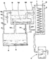
- the drawing illustrates an apparatus according to the invention, which comprises the chamber 2, the condenser 3, and the controls and plumbing 4 for handling liquid and vapour, which are features of the conventional systems referred to above.
- the chamber 2 is basically in the form of a vessel and is provided with heater elements 5, electric for instance, located in its base.
- the condenser 3 communicates with the chamber 2 by way of the controls and plumbing 4 aforementioned, and is provided with a coil 6 through which water is caused to circulate.
- Liquid produced by condensation in the condenser is directed into a separator 7 of conventional type, where the distilled water and solvent are separated, water being discharged and solvent being recycled back to the machine.
- a pre-distillation unit located between the chamber 2 and the condenser 3 and consisting, in substance, of a tank 9, and a heat exchanger lO located inside the tank.
- the tank 9 is in direct receipt, by way of a first pipeline 11 and a first solenoid valve 12, of mingled water, solvent and impurities directed into the apparatus on completion of a given cleaning cycle by the dry-cleaning machine of which it forms an integral part.
- the tank 9 also connects with the chamber 2 by way of a second pipeline 13 and second solenoid valve 14, this second pipeline connected to the bottom of the tank 9 in order to serve as a discharge from tank to chamber.
- the tank is also provided with an overflow pipe 15 controlled by a third solenoid valve 16, which likewise connects the tank with the chamber 2.
- the pre-distillation unit also comprises a duct 17 of relatively generous proprtions which joins the tank 9 and the condenser 3 in direct fashion.
- the heat exchanger 10 located inside the tank 9 is likewise connected both with the condenser 3 and with the chamber 2 in direct fashion; a first pipe 18, departing from the top outlet of the chamber 2, passes through the tank 9, and extends into the heat exchanger 10, whilst a second pipe 19 departing from the top of the heat exchanger 10, connects with the condenser 3.
- the unit also comprises a third pipe 20 departing from the bottom of the heat exchanger 10 and connecting with the bottom of the condenser 3.
- the three pipes 18, 19 and 20 are altogether free of control components, valves &c.
- Fluid thus introduced into the tank 9 is warmed by the heat exchanger 10 through which evaporated fluid heated in the chamber 2 exhausts to the condenser. Fluid heated in the chamber, and the vapour given off therefrom, will reach a temperature of approximately 121°C, as becomes evident in due course, and fluid in the tank 9 is raised to a temperature of approximately 87°C by the gradual heating process thus induced.
- the azeotropic mixture of perchloroethene and water will begin vaporizing.
- the mingled water and solvent in fact forms a stable mixture whose boiling point is 87°C, and this stable mixture forms only a part of the fluid content of the tank 9, as the quantity of water is relatively small in relation to that of the perchloroethene utilised in cleaning.
- the temperature inside the tank 9 remains steady, and vapour given off by the azeotropic mixture flows straight into the condenser via duct 17, there to be returned to the liquid state and flow out into the separator 7, where water and solvent are separated.
- the difference in temperature between vapour given off from within the chamber 2 and exhausted through the heat exchanger 10, and fluid contained in the tank 9, is such as to bring about a partial condensation within the heat exchanger 10; the liquid thus produced discharges from the exchanger toward the bottom of the condenser 3 by way of third pipe 20.
- Fluid in the chamber 2 is pure perchloroethene at this point, in practical terms, and the temperature is raised to the boiling point of that particular solvent, 121°C. Vapour given off is exhausted to the condenser via first pipe 18, heat exchanger 10 and second pipe 19, and heat therefrom is utilised in part to warm the next batch of mingled water-solvent-and-impurities directed from the machine into the tank 9 following the return of second solenoid valve 14 to closed position.
- the invention performs the fundamental object set forth, inasmuch as heat from the perchloroethene vapour is utilized to warm each new batch of mingled water-and-solvent for recycle, thereby reducing both the heating power requirement for such a process, and water consumption at the condenser stage, as well as cutting down the time necessary for distillation.
Landscapes
- Chemical & Material Sciences (AREA)
- Chemical Kinetics & Catalysis (AREA)
- Engineering & Computer Science (AREA)
- Textile Engineering (AREA)
- Vaporization, Distillation, Condensation, Sublimation, And Cold Traps (AREA)
Applications Claiming Priority (2)
| Application Number | Priority Date | Filing Date | Title |
|---|---|---|---|
| IT339884 | 1984-03-23 | ||
| IT03398/84A IT1179299B (it) | 1984-03-23 | 1984-03-23 | Dispositivo per rigenerare solventi in macchine lavasecco e simili |
Publications (3)
| Publication Number | Publication Date |
|---|---|
| EP0155919A2 true EP0155919A2 (de) | 1985-09-25 |
| EP0155919A3 EP0155919A3 (en) | 1987-02-04 |
| EP0155919B1 EP0155919B1 (de) | 1990-06-27 |
Family
ID=11106369
Family Applications (1)
| Application Number | Title | Priority Date | Filing Date |
|---|---|---|---|
| EP85830071A Expired EP0155919B1 (de) | 1984-03-23 | 1985-03-22 | Vorrichtung für die Wiederverwertung von Lösungsmitteln angewandt in chemischen Reinigungsanstalten und ähnlichen Anlagen |
Country Status (4)
| Country | Link |
|---|---|
| US (1) | US4637232A (de) |
| EP (1) | EP0155919B1 (de) |
| DE (1) | DE3578376D1 (de) |
| IT (1) | IT1179299B (de) |
Cited By (3)
| Publication number | Priority date | Publication date | Assignee | Title |
|---|---|---|---|---|
| EP0412377A3 (en) * | 1989-08-04 | 1991-05-02 | Environmental Technology Group Corp. | Mobile self-contained system for on-site recovery of solvents |
| EP0557257A1 (de) * | 1992-02-18 | 1993-08-25 | FIRBIMATIC S.r.l. | Wäschetrockenreinigungsmaschine |
| DE4314990A1 (de) * | 1993-05-06 | 1994-11-10 | Wurster Gerd | Anlage zum Eindampfen |
Families Citing this family (5)
| Publication number | Priority date | Publication date | Assignee | Title |
|---|---|---|---|---|
| IT1200216B (it) * | 1986-09-30 | 1989-01-05 | Sodibo Spa | Rilevatore di carico asciugato per macchina lavasecco |
| US6004403A (en) * | 1991-11-05 | 1999-12-21 | Gebhard Gray Associates | Solvent cleaning system |
| US5223126A (en) * | 1991-12-05 | 1993-06-29 | Air Quality Laboratories | System for decontaminating dry cleaning waste water with controlled pumping |
| US5525213A (en) * | 1994-06-23 | 1996-06-11 | Air Quality Corporation | System for decontamination dry cleaning waste water |
| US20040088846A1 (en) * | 2002-11-13 | 2004-05-13 | Unilever Home & Personal Care Usa, Division Of Conopco, Inc. | Method for in home servicing of dry cleaning machines |
Family Cites Families (5)
| Publication number | Priority date | Publication date | Assignee | Title |
|---|---|---|---|---|
| US1995064A (en) * | 1931-08-03 | 1935-03-19 | American Laundry Mach Co | Vent for garment cleaning systems |
| GB422427A (en) * | 1934-03-27 | 1935-01-11 | Alfred Jones | Improvements in dry cleaning apparatus |
| LU37746A1 (de) * | 1958-10-03 | |||
| IT1209790B (it) * | 1980-01-03 | 1989-08-30 | Zambelli Alessio | Depuratore a condensazione a circuito chiuso di scarichi gassosi di solventi clorurati impiegati nei laboratori di lavatura a secco ed in genere di solventi impiegati in piccoli impianti. |
| US4341599A (en) * | 1980-10-24 | 1982-07-27 | Watson W Keith R | Heating apparatus |
-
1984
- 1984-03-23 IT IT03398/84A patent/IT1179299B/it active
-
1985
- 1985-03-22 EP EP85830071A patent/EP0155919B1/de not_active Expired
- 1985-03-22 DE DE8585830071T patent/DE3578376D1/de not_active Expired - Lifetime
- 1985-04-08 US US06/720,752 patent/US4637232A/en not_active Expired - Fee Related
Cited By (6)
| Publication number | Priority date | Publication date | Assignee | Title |
|---|---|---|---|---|
| EP0412377A3 (en) * | 1989-08-04 | 1991-05-02 | Environmental Technology Group Corp. | Mobile self-contained system for on-site recovery of solvents |
| US5102503A (en) * | 1989-08-04 | 1992-04-07 | Environmental Technology Group Corporation | Mobile self-contained system for on-site recovery of solvents |
| EP0557257A1 (de) * | 1992-02-18 | 1993-08-25 | FIRBIMATIC S.r.l. | Wäschetrockenreinigungsmaschine |
| US5327751A (en) * | 1992-02-18 | 1994-07-12 | Firbimatic S.R.L. | Clothes dry-cleaning machine |
| DE4314990A1 (de) * | 1993-05-06 | 1994-11-10 | Wurster Gerd | Anlage zum Eindampfen |
| DE4314990C2 (de) * | 1993-05-06 | 1998-09-10 | Wurster Gerd | Anlage zum Eindampfen von Abwässern |
Also Published As
| Publication number | Publication date |
|---|---|
| IT8403398A0 (it) | 1984-03-23 |
| IT1179299B (it) | 1987-09-16 |
| DE3578376D1 (de) | 1990-08-02 |
| US4637232A (en) | 1987-01-20 |
| EP0155919A3 (en) | 1987-02-04 |
| EP0155919B1 (de) | 1990-06-27 |
Similar Documents
| Publication | Publication Date | Title |
|---|---|---|
| US20170349451A1 (en) | Device for the Purification of Water Using a Heat Pump | |
| US8241466B2 (en) | Distillation apparatus | |
| EP0155919A2 (de) | Vorrichtung für die Wiederverwertung von Lösungsmitteln angewandt in chemischen Reinigungsanstalten und ähnlichen Anlagen | |
| US4213830A (en) | Method for the transfer of heat | |
| CN103306109B (zh) | 一种家用干洗机、干洗方法及纯化回收干洗溶剂的方法 | |
| CN202610586U (zh) | 油水分离装置及使用该装置的干洗机 | |
| US5887454A (en) | Dry-cleaning machine with steam heated drying air | |
| KR101782556B1 (ko) | 진공감압 폐수처리장치 및 폐수처리 방법 | |
| US3479252A (en) | Apparatus for the degreasing of articles by means of a solvent | |
| US1897996A (en) | Preparation of strong hydrogen halide gas | |
| JP3577461B2 (ja) | 真空蒸留装置及び有機水性溶剤混合物の濃縮のためのその使用 | |
| EP1722026B1 (de) | Trockenreinigungsmaschine für Kleidungsstücke mit Lösungsmittelvernebler | |
| US4233120A (en) | Distillation method for solvent recovery | |
| CN204454676U (zh) | 一种乳化废水处理装置 | |
| KR940001419B1 (ko) | 진공증류법에 의한 폐수처리방법 | |
| CN107880930A (zh) | 一种节能的污油脱水装置及其处理方法 | |
| TWM589707U (zh) | 真空蒸餾濃縮設備 | |
| KR20210122722A (ko) | 증류기의 냉각장치 | |
| US4201631A (en) | Method for controlling the flow through a distillation apparatus and a device for carrying out the method | |
| JPS62208266A (ja) | 焼酎蒸溜廃液の減圧連続式濃縮処理装置 | |
| CN217854593U (zh) | 一种有机溶剂蒸馏的管式降膜蒸发器 | |
| EP3976283B1 (de) | Verfahren und system zum waschen von gegenständen aus einer industriellen produktion unter verwendung von lösungsmitteln | |
| CN206783352U (zh) | 一种烟气脱硫废水低温蒸发装置 | |
| JP2708387B2 (ja) | 木材用抽出方法およびそれに用いる装置 | |
| CN115888148A (zh) | 一种废油处理系统用脱水蒸馏塔及其使用方法 |
Legal Events
| Date | Code | Title | Description |
|---|---|---|---|
| PUAI | Public reference made under article 153(3) epc to a published international application that has entered the european phase |
Free format text: ORIGINAL CODE: 0009012 |
|
| AK | Designated contracting states |
Designated state(s): DE FR GB |
|
| PUAL | Search report despatched |
Free format text: ORIGINAL CODE: 0009013 |
|
| AK | Designated contracting states |
Kind code of ref document: A3 Designated state(s): DE FR GB |
|
| 17P | Request for examination filed |
Effective date: 19870204 |
|
| 17Q | First examination report despatched |
Effective date: 19880318 |
|
| GRAA | (expected) grant |
Free format text: ORIGINAL CODE: 0009210 |
|
| AK | Designated contracting states |
Kind code of ref document: B1 Designated state(s): DE FR GB |
|
| ET | Fr: translation filed | ||
| REF | Corresponds to: |
Ref document number: 3578376 Country of ref document: DE Date of ref document: 19900802 |
|
| PLBE | No opposition filed within time limit |
Free format text: ORIGINAL CODE: 0009261 |
|
| STAA | Information on the status of an ep patent application or granted ep patent |
Free format text: STATUS: NO OPPOSITION FILED WITHIN TIME LIMIT |
|
| 26N | No opposition filed | ||
| PGFP | Annual fee paid to national office [announced via postgrant information from national office to epo] |
Ref country code: DE Payment date: 20010319 Year of fee payment: 17 |
|
| PGFP | Annual fee paid to national office [announced via postgrant information from national office to epo] |
Ref country code: GB Payment date: 20010321 Year of fee payment: 17 |
|
| PGFP | Annual fee paid to national office [announced via postgrant information from national office to epo] |
Ref country code: FR Payment date: 20010406 Year of fee payment: 17 |
|
| REG | Reference to a national code |
Ref country code: GB Ref legal event code: IF02 |
|
| PG25 | Lapsed in a contracting state [announced via postgrant information from national office to epo] |
Ref country code: GB Free format text: LAPSE BECAUSE OF NON-PAYMENT OF DUE FEES Effective date: 20020322 |
|
| PG25 | Lapsed in a contracting state [announced via postgrant information from national office to epo] |
Ref country code: DE Free format text: LAPSE BECAUSE OF NON-PAYMENT OF DUE FEES Effective date: 20021001 |
|
| GBPC | Gb: european patent ceased through non-payment of renewal fee |
Effective date: 20020322 |
|
| PG25 | Lapsed in a contracting state [announced via postgrant information from national office to epo] |
Ref country code: FR Free format text: LAPSE BECAUSE OF NON-PAYMENT OF DUE FEES Effective date: 20021129 |
|
| REG | Reference to a national code |
Ref country code: FR Ref legal event code: ST |