EP0155947B1 - Reticulated products and their manufacture - Google Patents
Reticulated products and their manufacture Download PDFInfo
- Publication number
- EP0155947B1 EP0155947B1 EP84903158A EP84903158A EP0155947B1 EP 0155947 B1 EP0155947 B1 EP 0155947B1 EP 84903158 A EP84903158 A EP 84903158A EP 84903158 A EP84903158 A EP 84903158A EP 0155947 B1 EP0155947 B1 EP 0155947B1
- Authority
- EP
- European Patent Office
- Prior art keywords
- valleys
- crests
- strips
- sheet
- pattern
- Prior art date
- Legal status (The legal status is an assumption and is not a legal conclusion. Google has not performed a legal analysis and makes no representation as to the accuracy of the status listed.)
- Expired
Links
Images



Classifications
-
- B—PERFORMING OPERATIONS; TRANSPORTING
- B32—LAYERED PRODUCTS
- B32B—LAYERED PRODUCTS, i.e. PRODUCTS BUILT-UP OF STRATA OF FLAT OR NON-FLAT, e.g. CELLULAR OR HONEYCOMB, FORM
- B32B3/00—Layered products comprising a layer with external or internal discontinuities or unevennesses, or a layer of non-planar shape; Layered products comprising a layer having particular features of form
- B32B3/26—Layered products comprising a layer with external or internal discontinuities or unevennesses, or a layer of non-planar shape; Layered products comprising a layer having particular features of form characterised by a particular shape of the outline of the cross-section of a continuous layer; characterised by a layer with cavities or internal voids ; characterised by an apertured layer
- B32B3/28—Layered products comprising a layer with external or internal discontinuities or unevennesses, or a layer of non-planar shape; Layered products comprising a layer having particular features of form characterised by a particular shape of the outline of the cross-section of a continuous layer; characterised by a layer with cavities or internal voids ; characterised by an apertured layer characterised by a layer comprising a deformed thin sheet, i.e. the layer having its entire thickness deformed out of the plane, e.g. corrugated, crumpled
-
- B—PERFORMING OPERATIONS; TRANSPORTING
- B29—WORKING OF PLASTICS; WORKING OF SUBSTANCES IN A PLASTIC STATE IN GENERAL
- B29C—SHAPING OR JOINING OF PLASTICS; SHAPING OF MATERIAL IN A PLASTIC STATE, NOT OTHERWISE PROVIDED FOR; AFTER-TREATMENT OF THE SHAPED PRODUCTS, e.g. REPAIRING
- B29C51/00—Shaping by thermoforming, i.e. shaping sheets or sheet like preforms after heating, e.g. shaping sheets in matched moulds or by deep-drawing; Apparatus therefor
- B29C51/08—Deep drawing or matched-mould forming, i.e. using mechanical means only
-
- B—PERFORMING OPERATIONS; TRANSPORTING
- B29—WORKING OF PLASTICS; WORKING OF SUBSTANCES IN A PLASTIC STATE IN GENERAL
- B29D—PRODUCING PARTICULAR ARTICLES FROM PLASTICS OR FROM SUBSTANCES IN A PLASTIC STATE
- B29D24/00—Producing articles with hollow walls
-
- E—FIXED CONSTRUCTIONS
- E04—BUILDING
- E04C—STRUCTURAL ELEMENTS; BUILDING MATERIALS
- E04C2/00—Building elements of relatively thin form for the construction of parts of buildings, e.g. sheet materials, slabs, or panels
- E04C2/30—Building elements of relatively thin form for the construction of parts of buildings, e.g. sheet materials, slabs, or panels characterised by the shape or structure
-
- E—FIXED CONSTRUCTIONS
- E04—BUILDING
- E04C—STRUCTURAL ELEMENTS; BUILDING MATERIALS
- E04C2/00—Building elements of relatively thin form for the construction of parts of buildings, e.g. sheet materials, slabs, or panels
- E04C2/30—Building elements of relatively thin form for the construction of parts of buildings, e.g. sheet materials, slabs, or panels characterised by the shape or structure
- E04C2/32—Building elements of relatively thin form for the construction of parts of buildings, e.g. sheet materials, slabs, or panels characterised by the shape or structure formed of corrugated or otherwise indented sheet-like material; composed of such layers with or without layers of flat sheet-like material
- E04C2/326—Building elements of relatively thin form for the construction of parts of buildings, e.g. sheet materials, slabs, or panels characterised by the shape or structure formed of corrugated or otherwise indented sheet-like material; composed of such layers with or without layers of flat sheet-like material with corrugations, incisions or reliefs in more than one direction of the element
-
- E—FIXED CONSTRUCTIONS
- E04—BUILDING
- E04C—STRUCTURAL ELEMENTS; BUILDING MATERIALS
- E04C2/00—Building elements of relatively thin form for the construction of parts of buildings, e.g. sheet materials, slabs, or panels
- E04C2/30—Building elements of relatively thin form for the construction of parts of buildings, e.g. sheet materials, slabs, or panels characterised by the shape or structure
- E04C2/42—Gratings; Grid-like panels
-
- B—PERFORMING OPERATIONS; TRANSPORTING
- B32—LAYERED PRODUCTS
- B32B—LAYERED PRODUCTS, i.e. PRODUCTS BUILT-UP OF STRATA OF FLAT OR NON-FLAT, e.g. CELLULAR OR HONEYCOMB, FORM
- B32B2305/00—Condition, form or state of the layers or laminate
- B32B2305/02—Cellular or porous
- B32B2305/028—Hollow fillers; Syntactic material
-
- Y—GENERAL TAGGING OF NEW TECHNOLOGICAL DEVELOPMENTS; GENERAL TAGGING OF CROSS-SECTIONAL TECHNOLOGIES SPANNING OVER SEVERAL SECTIONS OF THE IPC; TECHNICAL SUBJECTS COVERED BY FORMER USPC CROSS-REFERENCE ART COLLECTIONS [XRACs] AND DIGESTS
- Y10—TECHNICAL SUBJECTS COVERED BY FORMER USPC
- Y10T—TECHNICAL SUBJECTS COVERED BY FORMER US CLASSIFICATION
- Y10T156/00—Adhesive bonding and miscellaneous chemical manufacture
- Y10T156/10—Methods of surface bonding and/or assembly therefor
- Y10T156/1002—Methods of surface bonding and/or assembly therefor with permanent bending or reshaping or surface deformation of self sustaining lamina
- Y10T156/1003—Methods of surface bonding and/or assembly therefor with permanent bending or reshaping or surface deformation of self sustaining lamina by separating laminae between spaced secured areas [e.g., honeycomb expanding]
-
- Y—GENERAL TAGGING OF NEW TECHNOLOGICAL DEVELOPMENTS; GENERAL TAGGING OF CROSS-SECTIONAL TECHNOLOGIES SPANNING OVER SEVERAL SECTIONS OF THE IPC; TECHNICAL SUBJECTS COVERED BY FORMER USPC CROSS-REFERENCE ART COLLECTIONS [XRACs] AND DIGESTS
- Y10—TECHNICAL SUBJECTS COVERED BY FORMER USPC
- Y10T—TECHNICAL SUBJECTS COVERED BY FORMER US CLASSIFICATION
- Y10T156/00—Adhesive bonding and miscellaneous chemical manufacture
- Y10T156/10—Methods of surface bonding and/or assembly therefor
- Y10T156/1002—Methods of surface bonding and/or assembly therefor with permanent bending or reshaping or surface deformation of self sustaining lamina
- Y10T156/1051—Methods of surface bonding and/or assembly therefor with permanent bending or reshaping or surface deformation of self sustaining lamina by folding
-
- Y—GENERAL TAGGING OF NEW TECHNOLOGICAL DEVELOPMENTS; GENERAL TAGGING OF CROSS-SECTIONAL TECHNOLOGIES SPANNING OVER SEVERAL SECTIONS OF THE IPC; TECHNICAL SUBJECTS COVERED BY FORMER USPC CROSS-REFERENCE ART COLLECTIONS [XRACs] AND DIGESTS
- Y10—TECHNICAL SUBJECTS COVERED BY FORMER USPC
- Y10T—TECHNICAL SUBJECTS COVERED BY FORMER US CLASSIFICATION
- Y10T156/00—Adhesive bonding and miscellaneous chemical manufacture
- Y10T156/10—Methods of surface bonding and/or assembly therefor
- Y10T156/1052—Methods of surface bonding and/or assembly therefor with cutting, punching, tearing or severing
- Y10T156/1062—Prior to assembly
- Y10T156/1066—Cutting to shape joining edge surfaces only
-
- Y—GENERAL TAGGING OF NEW TECHNOLOGICAL DEVELOPMENTS; GENERAL TAGGING OF CROSS-SECTIONAL TECHNOLOGIES SPANNING OVER SEVERAL SECTIONS OF THE IPC; TECHNICAL SUBJECTS COVERED BY FORMER USPC CROSS-REFERENCE ART COLLECTIONS [XRACs] AND DIGESTS
- Y10—TECHNICAL SUBJECTS COVERED BY FORMER USPC
- Y10T—TECHNICAL SUBJECTS COVERED BY FORMER US CLASSIFICATION
- Y10T428/00—Stock material or miscellaneous articles
- Y10T428/19—Sheets or webs edge spliced or joined
- Y10T428/192—Sheets or webs coplanar
- Y10T428/193—Double faced corrugated sheets or webs connected
-
- Y—GENERAL TAGGING OF NEW TECHNOLOGICAL DEVELOPMENTS; GENERAL TAGGING OF CROSS-SECTIONAL TECHNOLOGIES SPANNING OVER SEVERAL SECTIONS OF THE IPC; TECHNICAL SUBJECTS COVERED BY FORMER USPC CROSS-REFERENCE ART COLLECTIONS [XRACs] AND DIGESTS
- Y10—TECHNICAL SUBJECTS COVERED BY FORMER USPC
- Y10T—TECHNICAL SUBJECTS COVERED BY FORMER US CLASSIFICATION
- Y10T428/00—Stock material or miscellaneous articles
- Y10T428/24—Structurally defined web or sheet [e.g., overall dimension, etc.]
- Y10T428/24479—Structurally defined web or sheet [e.g., overall dimension, etc.] including variation in thickness
-
- Y—GENERAL TAGGING OF NEW TECHNOLOGICAL DEVELOPMENTS; GENERAL TAGGING OF CROSS-SECTIONAL TECHNOLOGIES SPANNING OVER SEVERAL SECTIONS OF THE IPC; TECHNICAL SUBJECTS COVERED BY FORMER USPC CROSS-REFERENCE ART COLLECTIONS [XRACs] AND DIGESTS
- Y10—TECHNICAL SUBJECTS COVERED BY FORMER USPC
- Y10T—TECHNICAL SUBJECTS COVERED BY FORMER US CLASSIFICATION
- Y10T428/00—Stock material or miscellaneous articles
- Y10T428/24—Structurally defined web or sheet [e.g., overall dimension, etc.]
- Y10T428/24479—Structurally defined web or sheet [e.g., overall dimension, etc.] including variation in thickness
- Y10T428/24612—Composite web or sheet
-
- Y—GENERAL TAGGING OF NEW TECHNOLOGICAL DEVELOPMENTS; GENERAL TAGGING OF CROSS-SECTIONAL TECHNOLOGIES SPANNING OVER SEVERAL SECTIONS OF THE IPC; TECHNICAL SUBJECTS COVERED BY FORMER USPC CROSS-REFERENCE ART COLLECTIONS [XRACs] AND DIGESTS
- Y10—TECHNICAL SUBJECTS COVERED BY FORMER USPC
- Y10T—TECHNICAL SUBJECTS COVERED BY FORMER US CLASSIFICATION
- Y10T428/00—Stock material or miscellaneous articles
- Y10T428/24—Structurally defined web or sheet [e.g., overall dimension, etc.]
- Y10T428/24628—Nonplanar uniform thickness material
-
- Y—GENERAL TAGGING OF NEW TECHNOLOGICAL DEVELOPMENTS; GENERAL TAGGING OF CROSS-SECTIONAL TECHNOLOGIES SPANNING OVER SEVERAL SECTIONS OF THE IPC; TECHNICAL SUBJECTS COVERED BY FORMER USPC CROSS-REFERENCE ART COLLECTIONS [XRACs] AND DIGESTS
- Y10—TECHNICAL SUBJECTS COVERED BY FORMER USPC
- Y10T—TECHNICAL SUBJECTS COVERED BY FORMER US CLASSIFICATION
- Y10T428/00—Stock material or miscellaneous articles
- Y10T428/24—Structurally defined web or sheet [e.g., overall dimension, etc.]
- Y10T428/24628—Nonplanar uniform thickness material
- Y10T428/24669—Aligned or parallel nonplanarities
Definitions
- This invention relates to reticulated materials of substantially planar configuration which have been formed by the conjunction of a plurality of strips of nonplanar sheet material.
- Such products are known in which the strips of nonplanar sheet material lie substantially perpendicular to the plane of the reticulated material so that the edges of the strips lie coplanar with the reticulated material and form opposite surfaces of it.
- projections on the nonplanar sheets are opposed and brought into abutment to leave spaces between adjacent sheets and thus form the reticulated structure of the composite material.
- the abutted projections in these materials are permanently bonded to ensure shear strength between the strips.
- nonplanar sheets One type of method and apparatus which may be used to form nonplanar sheets is that described, for example, in Australian Patent Specification No. 460,849 (AU-B-48 569/72).
- This specification describes the cuspation of nonplanar sheets through the action on a sheet of thermoplastic material of a patterned array of projections on opposed tools.
- the nonplanar sheets formed in accordance with the disclosure of this specification have projections of substantially equal height extending from each surface of the sheet and are generally adapted to nest within sheets of similar configuration so that substantially the whole of the opposed surfaces of adjacent sheets are in contact.
- Cuspation forming technology has been found particularly useful for the production of sheets to be used in accordance with the present invention. This is at least partly because of the wide range of different patterns which may be formed using this technology and also because the technology allows the substantially continuous production of substantial lengths of nonplanar sheet material. Furthermore cuspation is a unique process in that it provides structurally efficient materials distribution while permitting variable vertical stretch. Accordingly it is useful to adopt and extend the terminology of the cuspation process in describing the present invention.
- Bilateral cuspation by counter-thrust of opposed tools carrying cold projections draws hot thermoplastic sheet upwardly and downwardly forming cusps and inverted cusps.
- the cusp walls are formed by free stretch since the plan area of tool projections is usually less than 5% of the sheet plan area.
- the position of the projections is based on a lattice or plane tessellation.
- This lattice can be triangular or preferably square.
- the areas of the lattice may be considered as alternately black and white, as in a chessboard.
- the upper and lower opposed tools are then considered as two superposed lattices, black areas over black areas and white over white.
- On the lower tool at the centre of every "black” area is mounted a vertical projection.
- the upper tool has projections on the "white” area. In effect every up-projection lies between four down projections and vice versa, except at the lattice edges.
- the distance between adjacent cusps extending in the same direction (which is the same length as the diagonal of the lattice square) is thus the wavelength of the pattern.
- each sheet surface provides the regular amplitude of the pattern wave.
- the deformed sheet is generally planar in form as it is encompassed by an envelope comprising the coplanar surfaces contacting all cusps in each oppositely directed set.
- machine direction is synonomous with the length direction of the sheet.
- references to the width of the sheet or transverse measurement refer to the direction at right angles to the machine direction.
- nonplanar sheet material can be formed between rolls; die forming or dip-casting technology can be used to produce continuous or batch lengths of nonplanar material; and conventional casting methods can be used for noncontinuous production.
- a reticulated material of substantially planar configuration formed by the conjunction of a plurality of strips of nonplanar sheet material in which the strips lie substantially perpendicular to the plane of the reticulated material, the edges of the strips lying coplanar with the reticulated material and forming opposite surfaces thereof, each strip of nonplanar sheet material being formed on each opposite surface with a pattern of crests and valleys of repetitive wavelength such that each pattern repeat contains at least two crests and at least two valleys, wherein in each pattern repeat the height of at least one crest or valley on at least one surface of the strip is different from that of at least one of the other crests and valleys on said surface, characterized in that the said height difference is varied regularly to produce a corrugation along the strip having a wavelength greater than the wavelength of the crests and valleys, and in that adjacent strips are abutted with the corrugation opposed to interfit at least one crest in a valley of each opposed corrugation.
- the subclaims 2 to 10 provide preferred embodiments of the reticulated marerial of the invention.
- the present invention also provides a method of preparing a reticulated material of substantially planar configuration in which a plurality of strips of nonplanar material lie in conjunction with the strips substantially perpendicular to the plane of the reticulated material, characterized by forming a plurality of substantially similar strips of nonplanar material each having a pattern of crests and valleys of repetitive wavelength such that each pattern repeat contains at least two crests and at least two valleys, wherein in each pattern repeat the height of at least one crest or valley on at least one surface of the strip is different from that of the other crests and valleys on said surface, and wherein the said height different is varied regularly to produce a corrugation along the strip having a wavelength greater than the wavelength of the crests and valleys; abutting adjacent strips with the corrugations opposed and interfitting at least one crest in a valley of each opposed corrugation. Alternate methods of production of the reticulated material will be discussed hereafter.
- the products of the present invention are characterized firstly by the repetitive pattern of crests and valleys formed on each opposite surface of the sheets which are interfitted in the specified manner to form the composite reticulated material of the invention.
- the essential features outlined above are incorporated in the crest and valley pattern, a relatively wide variation of patterns is possible. These variations are described more fully later in this specification with reference to the accompanying drawings which assist in an understanding of the complex shapes involved.
- crest and "valley” have been chosen for use in broadly describing and defining the present invention to assist in forming a mental picture of the sheet materials which will assist in distinguishing between the oppositely directed cusps.
- crest is used for an upwardly directed cusps of a horizontal sheet and the term “valley” for the downwardly directed cusps of the sheet.
- the crests and valleys have sides of approximately conical form, thus approaching a peak. It is to be understood however that such peaked crests and valleys are not an essential feature of the invention.
- crests and valleys may be formed with nonconical sides, for example as ridges running in any desired direction relative to the length of the sheet. Crests and valleys with conical sides may not form a sharp peak but may be deliberately flattened by the use of a nonpointed forming tool.
- the crests and valleys may also be in cruciform or curved shapes.
- the present invention preferably employs tooling having the same regular projection spacing as discussed above for the prior art cuspation procedure.
- the projection heights vary so that the envelope of each respective upper and lower tool is profiled to a waveform having a repeat dimension which is an integral multiple of two or more times the wavelength of the tooling pattern.
- This envelope waveform may be a corrugation or any other standing waveform in two dimensions, our preferred case being a flat-topped corrugation in the machine direction.
- the tooling patterns of the present invention thus embody both the bilateral cuspation introduced by interdigitation and a relatively larger waveform as provided by the tooling profile.
- the cuspation induced by interdigitation may be varied in depth depending on the relative approach of the tools but the tooling profile wavelength is fixed for any one tool pattern.
- the minor wavelength is determined in the same manner as for the simple cuspation previously described.
- the major wavelength of the repeated pattern variation is determined from the tool profile.
- the amplitude of the minor waveform in the products of the present invention is no longer constant because the planar sheet starting material is deformed both by the tooling projections and by the waveform tooling profile. We refer therefore to the "interdigitative depth" of the crests and valleys of the sheets used in the present invention, rather than to their amplitude.
- the nonplanar sheets used to form the reticulated materials of the present invention are normally produced as wide continuous sheets more than one metre wide.
- the width of the sheets or strips used to form the reticulated material may be any multiple of half the minor wavelength so that the cuspated sheet may yield as many as one hundred strips each equal to the thickness when reformed into reticulated material. It is a production advantage of the present invention that formed sheets can be subdivided longitudinally to form relatively narrow strips which are then used in forming the reticulated materials of the invention. The requirements for subdivision of sheets as formed will be discussed more fully hereafter.
- the tool projection shape and the interdigitative depth are specially chosen.
- the interdigitative depth increases the interlattice cross section becomes more and more sinuous, thus is able to act in semi-rigid media as a spring.
- the extent of interdigitation and hence the interdigitative depth can be readily varied if the cuspation process is used as the manufacturing method.
- a second special case requires maximisation of vertical load bearing strength. In this situation it is essential to minimise the sinuousity of the cell wall.
- the interlock is a packed group of cusps within cusps giving excellent column strength. Such interlock is shown in Fig. 12 later described.
- cuspation thermoforming is a preferred form by which the sheets used in the present invention may be prepared.
- Figures 1 and 2 are included in the present specification for comparative purposes and to assist an understanding of the basic principles of cuspation thermoforming and the developments to these principles which have been made in the production of the sheets used in the present invention.
- Figure 1 shows a nonplanar sheet which may be formed by cuspation of the sheet in a plastic state between opposed tools each having a patterned array of projections.
- the opposed patterns of projections are such that the projections on the respective tools can be interposed so that crests formed on one surface of the sheet are equally spaced from valleys formed on the other surface of the sheet.
- the peak of each crest and each valley is located at the intersection of a square grid, the grid lines of which run parallel with and transverse to the sides of the strip. On either surface, diagonal lines of peaks run parallel at 45° to the square grid lines.
- each sheet has on each opposite surface a pattern of crests and valleys of repetitive wavelength such that each pattern repeat contains at least two crests and at least two valleys.
- the height of at least one crest or valley on at least one surface of the sheet in each pattern repeat is different from that of the other crests and valleys on the selected surface and this height difference is varied regularly to produce a corrugation along the sheet which has a wavelength greater than the wavelength of the crests and the valleys, adjacent strips can be abutted with the corrugations opposed to interfit at least one crest in a valley of each opposed corrugation.
- Figure 3 illustrates diagrammatically the type of tool pattern which may be used to produce by cuspation one preferred form of sheet used in the present invention.
- This diagram shows the pattern in which the interposed projections of the two tools are arranged.
- the upwardly movable tool projections are indicated simply by the letters S and L while the downwardly movable tool projections are indicated by the same letters which have been circled.
- the letters S and L indicate the relative lengths of the projections with all the S projections being the same length as each other and relatively shorter than the L projections.
- the L projections are also all of the same length as each other.
- the long projections of one tool are, as shown, interposed between the short projections of the opposing tool.
- the long and short projections should then be opposed as directly as possible to maximise corrugation of the product sheet.
- corrugated sheet in accordance with the invention can also be produced if projections of the same length on opposed tools are interposed.
- Figure 4 is a diagrammatic presentation of an edge view of the type of sheet formed using the tooling pattern of Figure 3. This diagrammatic view is taken along an edge of sheet cut along the line forming the midpoint between adjacent longitudinally extending rows of crests and valleys.
- the line taken for Figure 4 is shown as IV-IV in Figure 3.
- the thick corrugated line 1 in the center of Figure 4 follows the configuration of the cut edge.
- the full line 2 shows the height of the crests and valleys extending longitudinally of the sheet nearest to the cut edge and the broken line 3 shows the height of the crests and valleys in the adjacent longitudinally extending line of crests and valleys.
- the wavelength between adjacent crests is indicated by w and it will be appreciated that this distance is greater than that measured in the plane of Figure 4 as it is taken between two peaks, one of which is closer to the plane of the paper than the other.
- the wavelength C is that of the transverse corrugation formed by the repetition of the height differences in the pattern. C is shown as extending between the peaks of two valleys in the longitudinal row nearest to the edge of the diagram. It will be appreciated that this wavelength is the same as the wavelength of the curved edge shown in the center of the diagram.
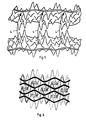
- Figure 5 is a diagrammatic perspective representation of two sheets of the form produced by the tooling pattern of Figure 3.
- the arrows 4 extending from the lower sheet indicate the interfitting of the lower crests into the valleys of the upper sheet.
- the conjunction of four such sheets is diagrammatically illustrated in Figure 6.
- the reticulated nature of the material formed by the conjunction of these sheets is evident in Figure 6 which shows the transversely extending pockets 5 which remain when the crests and valleys of the opposed corrugations are interfitted.
- Figures 7A to 7C we have illustrated some additional alternative tooling configurations in the same manner as Figure 3. Using the same pattern terminology as indicated above for Figure 3, it will be seen that Figure 7A illustrates a one long/two short pattern, Figure 7B illustrates a two long/three short pattern, and Figure 7C illustrates a three long/three short pattern.
- tooling configurations may be used to produce sheets for use in the present invention by one or more of (a) further varying the numbers of the alternating long projection and short projection rows, (b) moving one tool relative to the other and thus altering the interpositioning of the respective projections, and (c) introducing occasional projections of the other length into the respective transverse rows of long or short tools.
- tooling configurations may be used in which more than two alternative projection lengths are used.
- Figure 8 contains a number of schematic edge views. It must be appreciated that these schematic end views have been simplified by ignoring the crests and valleys produced by the shorter tool projections and showing only the crests and valleys for the first two longitudinally extending rows of crests and valleys produced by the longer tooling projections. That is, these schematic views show only the longer crests and valleys in the row nearest the edge and in the row next from the edge. This simplification may be more clearly appreciated by comparing the schematic edge view of Figure 8A with the more detailed diagrammatic views of the corresponding two long/ two short pattern sheets in Figures 4 and 6.
- Figure 8A shows the preferred form of interfitting the sheets shown in Figures 4, 5 and 6 and is a further simplified version of Figure 6.
- Figures 8B, 8C and 8D show the preferred forms of interfitting the sheets produced by the tooling patterns of Figures 7A, 7B and 7C respectively. It will be apparent that the more complex sheet forms may be interfitted in other ways as shown, for example in Figure 8E which is a less-preferred variation of Figure 8D.
- adjacent corrugated sheets are abutted with the corrugations opposed and at least one crest is interfitted in a valley of each opposed corrugation.
- the abutment of the sheets and the interfitting of the crests and valleys may be achieved in a variety of ways. For example, if sheets aligned one above the other are offset longitudinally by half the wavelength of their corrugations, the corrugations will abut. As an alternative, if a single sheet is cut longitudinally and the two parts folded together like a book, the corrugations will nest. The particular sequence of operations used will depend on the form of the. sheets which are to be abutted and interfitted and on the form and desired end use of the product reticulated material.
- the full width or any lesser width which includes at least one repeat of the pattern in the original sheet can be abutted corrugation to corrugation with adjacent sheets to form an open nested stack.
- Stacks of substantial width can, if necessary after stabilization by clamping or otherwise, be sliced vertically in the machine direction to obtain a plurality of submultiples of the original stack which, when laid horizontally, will themselves be sheet materials having a width corresponding to the height of the original stack.
- sheets of substantial width are divided into submultiples referred to herein as strips, having a width which corresponds to the desired height of the product stack of reticulated material.
- the collation of adjacent sheets into the open nested reticulated materials of the present invention may be conducted as a substantially continuous process by the use of preformed and possibly stored sheets or strips of nonplanar material having the desired pattern.
- Fig. 9 Binary collation is shown in Fig. 9 where 15 strips are initially paired as far as possible: 1-2, 3-4, 5-6, 7-8, 9-10, 11-12, 13-14.
- the odd strip 15 is not involved in the first folding and abutment step but enters the process in the next step being folded to abut with strip 14 in the pair 13-14.
- the free surfaces in the pairs 1-2/3-4, 5-6n-8, 9-10/11-12 are abutted in the second step.
- the free surfaces of strips 4 and 5 and of 12 and 13 respectively are abutted, and the final step abuts the free surfaces of strips 8 and 9.
- a sheet of nonplanar material may be slit to form a plurality of longitudinally extending strips connected at intervals by relatively short webs of unslit material.
- the webs of unslit material are located across the peaks of the corrugations and alternate transversely of the sheet so that slits with webs across the peaks of upwardly extending corrugations alternate with slits with webs across the peaks of downwardly extending corrugations.
- This form of partial slitting can be used when the depth of the crests and valleys is sufficiently shallow to allow alternate reverse folding along the slit lines and nesting of opposed crests and valleys without interference as the folding brings the corrugations on adjacent strips into abutment.
- preformed strips having the width desired for the final height of the product reticulated material can be folded back along themselves at regularly spaced predetermined intervals to provide a mat-like structure of the form illustrated in Figure 10.
- Preformed nonplanar sheets may be stored prior to use in coils or otherwise and may be fed through slitting and collating machines to form the reticulated material of the invention.
- a preformed sheet may be cut into strips by a fixed cutting bar and adjacent strips are then half rotated in an alternative sense prior to abutment of adjacent strips followed by successive abutment of adjacent strip groups until the fully assembled material is produced.
- the binary collation procedure described above is preferably used in this procedure.
- the reticulated material thus formed is preferably stabilized before being cut to desired lengths. It is an advantage of the present invention that, while the width of reticulated material initially produced is limited by the width of the original nonplanar sheet and by the extent of subdivision which has been applied to this sheet to produce the desired height of reticulated material, the reticulated material may be produced to have any desired length. By moving the desired length of product material sideways after cutting from the production line, successive product sheets can be abutted sideways to form any desired width of the product.
- Figure 11 illustrates one form of production line using two coils 10, 11 of differently coloured preformed nonplanar sheet which are slit at 12 and 13 respectively and interspersed prior to the collation step at 14. Interspersion of two sheets is not necessary but may be used where two colour product is desired.
- the product reticulated material is stabilized by flame bonding at 15 to a planar sheet from roll 16. The stabilized product is held between clamp roll 17 and belt 18 then cut at 19 to the desired length before being moved sideways. If desired a selvedge 20 of the stabilizing sheet material may be left to assist in connection of the individual product sheets to an end product sheet of reticulated material 21.
- stabilization may be achieved by bonding a sheet of appropriate material to one surface of the reticulated product.
- the product may be backed by fusion or adhesive bonding to a sheet, film, fabric or plastic mesh on one side only. Fusion by flame bonding is presently preferred.
- Alternative means of stabilizing the reticulated product include stitching or tufting fastening strands from surface to surface of the product material and securing a strand at least once around each pair of adjacent strips. Fastening strands may also be threaded through at least some of the interfitted crests and valleys and secured at each opposite edge of the material. To assist the latter form of stabilization the peaks of the crests or valleys may be cut off or pierced during or after the formation of the material and cords or wires passed through the colinear passages so created.
- Other alternative forms of stabilization will be apparent to those skilled in the art. For example a stack or sheet of product material may be stitched into an overwrapping bolster.
- the reticulated material may be at least partly filled with a material which will set to stabilize or otherwise modify the properties of the product structure.
- the pockets can be filled with an elastic foam such as rubber latex foam or a setting cement.
- the structure may be partially embedded in a setting material.
- Other materials which modify the properties of the product material may also be filled into the pockets which characterize the product material of the invention.
- the product materials may also be used to reinforce foam such as latex or polyurethane flexibles which have natural resilience but are of low grade in structural merit and/or specific resilience.
- foam such as latex or polyurethane flexibles which have natural resilience but are of low grade in structural merit and/or specific resilience.
- reticulated cuspated structures based on pliable (but not rubbery) plastics act as high specific resilience reinforcers for foam rubbers.
- a heavily corona-discharge treated 150 um polypropylene reticulated product of two long/two short pattern configuration and of 10 mm layer thickness was tested. Small wavelength w was 4 mm and large wavelength C was 24 mm stabilized by a 20 um film on one side and weight 220 gsm.
- S.B.R. rubber latex foam was spread to fill the reticulation cells and the product was dried in a tunnel oven at 130 deg Celsius for ten minutes.
- the resultant highly resilient composite cushion supported five times the indent load for equal deflection over the latex alone, and 1.5 times that of the unfilled product alone.
- Such composite cushions mayform'an integral part of underlay, mat, integral carpet back, carpet tile, resilient smooth flooring and doormats, etc. Their appearance is good and the cuspated core confers useful abrasion resistance. A synergistic effect on properties for the composite over its components is apparent, and is due in part to the foam fill further bracing the cuspated cells forcing the foam to act as a column under side constraints.
- Urethane flexible foams also produce cost efficient composites and their adherence is such that no priming step is normally required.
- nonplanar sheet used to produce the product of the present invention will vary'greatly depending on the desired nature of the end product.
- the types of product illustrated so far in this specification have relatively fine crests and valleys of substantial height and wavelength separation compared with the thickness of the material from which they are formed. However, both the shape and spacing of the crests and valleys may be varied.
- coarse patterns the material forming the sheet is usually relatively thin with respect to the open volume in the product material.
- the expression "bulk density” is used to provide a measure of how many times lighter the product material is than an equal volume of the solid material from which it is formed. For example, balsa wood which is mostly air, has a bulk density of about 20, very light plastic foams have bulk densities of 50.
- a heavy load bearing mat made from the material of the present invention and intended for use as a light air strip or temporary road will have a bulk density around 10.
- Resilient open structures such as flexible synthetic foams also act as cushions but their cellular structure is typically so fine that both abrasion resistance and tear strength are low while the huge internal surface area makes such materials dangerously inflammable.
- Diagrammatic cross sections of reticulated structures with different interdigitative depths are shown in Fig. 13. Irr Fig. 13 (a) the interdigitative depth is 1 mm, in Fig. 13 (b) it is 4 mm and in Fig. 13 (c) it is 7 mm.
- thermoplastic material which may be used to produce the products of the present invention is not narrowly limited.
- Pliable materials such as low and high density polyethylene, often with vinyl or acetate comonomer and the softer grades of acrylonitrile-butadiene styrene are appropriate for resilient goods. Certain rubbers may be used.
- Harder plastics such as polypropylene, thermoplastic polyester, polystyrene, polyphenylene oxide, unplasticized vinyl and high impact acrylic- are all applicable. Glassy melt materials such as inorganic glass or slag may be used. So also may edible thermoplastic such as candy. Superplastic or other metal alloys may also be used.
- the products of the invention are thus reticulated materials in which the junctions between adjacent sheets or strips are given shear strength by interfitting abutments. However, desirable pliability of the products is maintained because the interfitted abutments are optionally demountable. The mat-like products can thus be rolled up when not in use.
- interfitted products of the invention are able readily to dissipate stress concentrations. Variation of the interdigitative depths and the form of the cusps allows variation of the load- bearing rigidity from stiff to resilient.
- honeycomb In other lightweight cellular constructs such as honeycomb and foamed plastics the object is to obtain cost-efficient properties especially in terms of strength and resilience. Limitations on these micro-engineered materials arise partly from the fact that specific properties are tied together. For example in rigid and flexible foams low density is always associated with ultra-thin cell walls and huge internal area; hence, these extremely intricate materials tend to have poor abrasion strength. These facts, in turn, derive from the physics of stable bubble aggregates. In honeycomb, no useful strength as a core exists until the component sheets are glued together. The pliability of a honeycomb system bonded to a one face sheet is then very limited. Further, honeycomb while admittedly having admirable strength as a column, is devoid of toughness and springiness and always subject under destructive loads to a catastrophic irrecoverable collapse.
- Degree of interlock is a separate function varied by depth of interdigitation; in turn interdigitative depth steeply influences resilience.
- Cell shape and mode of flexure under load are also elective variables.
- Product sheet height is also readily varied by altering the width of the strips forming the composite material. This width can be any selected number of times the half wavelength between the crests and valleys.
- blends of weights and qualities of material are elective.
- any reticulated product may be backfilled with any agent selected to produce synergistic benefits.
- the products may be specifically designed for bulk factor (apparent density), load- bearing, loadsharing and shear properties, pile depth, cell size, springiness, abrasion resistance, composite properties, yield profile under load and shock resistance, all as separate and adjustable features. It is a remarkable feature that the properties developed while the interlock is in place and which would be typical of a rigid structure disappear as the material disarticulates and rolls up on zero radius.
Landscapes
- Engineering & Computer Science (AREA)
- Architecture (AREA)
- Civil Engineering (AREA)
- Structural Engineering (AREA)
- Mechanical Engineering (AREA)
- Slide Fasteners, Snap Fasteners, And Hook Fasteners (AREA)
- Laminated Bodies (AREA)
- Prostheses (AREA)
Applications Claiming Priority (2)
| Application Number | Priority Date | Filing Date | Title |
|---|---|---|---|
| AU1090/83 | 1983-08-29 | ||
| AUPG109083 | 1983-08-29 |
Publications (3)
| Publication Number | Publication Date |
|---|---|
| EP0155947A1 EP0155947A1 (en) | 1985-10-02 |
| EP0155947A4 EP0155947A4 (en) | 1986-01-28 |
| EP0155947B1 true EP0155947B1 (en) | 1989-03-22 |
Family
ID=3770294
Family Applications (1)
| Application Number | Title | Priority Date | Filing Date |
|---|---|---|---|
| EP84903158A Expired EP0155947B1 (en) | 1983-08-29 | 1984-08-28 | Reticulated products and their manufacture |
Country Status (18)
| Country | Link |
|---|---|
| US (1) | US4587147A (it) |
| EP (1) | EP0155947B1 (it) |
| JP (1) | JPS61500015A (it) |
| BR (1) | BR8407040A (it) |
| CA (1) | CA1214305A (it) |
| DE (1) | DE3477358D1 (it) |
| DK (1) | DK189085D0 (it) |
| ES (1) | ES8707892A1 (it) |
| FI (1) | FI851672A7 (it) |
| GB (1) | GB2145662B (it) |
| GR (1) | GR80232B (it) |
| HK (1) | HK83787A (it) |
| IT (1) | IT1196740B (it) |
| MY (1) | MY8700536A (it) |
| NZ (1) | NZ209336A (it) |
| PT (1) | PT79148B (it) |
| SG (1) | SG24187G (it) |
| ZA (1) | ZA846761B (it) |
Families Citing this family (6)
| Publication number | Priority date | Publication date | Assignee | Title |
|---|---|---|---|---|
| US5205891A (en) * | 1987-08-28 | 1993-04-27 | Hunter Douglas, Inc. | Method for manufacturing an expandable collapsible product |
| US4943454A (en) * | 1987-08-28 | 1990-07-24 | Hunter Douglas, Inc. | Expandable collapsible product and method and apparatus for its manufacture |
| AU651604B2 (en) * | 1990-07-27 | 1994-07-28 | Nippon Petrochemicals Company Limited | Tier sheets and method for producing the same |
| US7049548B1 (en) | 2005-03-21 | 2006-05-23 | The Boeing Company | System and method for processing a preform vacuum vessel to produce a structural assembly |
| US7431196B2 (en) * | 2005-03-21 | 2008-10-07 | The Boeing Company | Method and apparatus for forming complex contour structural assemblies |
| US12023606B2 (en) | 2020-09-01 | 2024-07-02 | Eljen Corporation | Textured core sheets for fluid drainage unit |
Family Cites Families (4)
| Publication number | Priority date | Publication date | Assignee | Title |
|---|---|---|---|---|
| US3227598A (en) * | 1960-12-02 | 1966-01-04 | Wayne F Robb | Core structure |
| JPS5112856B1 (it) * | 1967-05-09 | 1976-04-22 | ||
| US4025996A (en) * | 1971-08-11 | 1977-05-31 | Saveker David R | Sinusoidal structural element |
| BE792077A (it) * | 1971-11-29 | 1973-03-16 | Ici Australia Ltd |
-
1984
- 1984-08-24 NZ NZ209336A patent/NZ209336A/en unknown
- 1984-08-28 GR GR80232A patent/GR80232B/el unknown
- 1984-08-28 EP EP84903158A patent/EP0155947B1/en not_active Expired
- 1984-08-28 JP JP59503243A patent/JPS61500015A/ja active Granted
- 1984-08-28 ES ES535467A patent/ES8707892A1/es not_active Expired
- 1984-08-28 CA CA000461990A patent/CA1214305A/en not_active Expired
- 1984-08-28 BR BR8407040A patent/BR8407040A/pt unknown
- 1984-08-28 PT PT79148A patent/PT79148B/pt unknown
- 1984-08-28 US US06/740,261 patent/US4587147A/en not_active Expired - Fee Related
- 1984-08-28 DE DE8484903158T patent/DE3477358D1/de not_active Expired
- 1984-08-28 FI FI851672A patent/FI851672A7/fi not_active Application Discontinuation
- 1984-08-28 GB GB08421695A patent/GB2145662B/en not_active Expired
- 1984-08-29 ZA ZA846761A patent/ZA846761B/xx unknown
- 1984-08-29 IT IT67860/84A patent/IT1196740B/it active
-
1985
- 1985-04-26 DK DK189085A patent/DK189085D0/da not_active Application Discontinuation
-
1987
- 1987-03-09 SG SG241/87A patent/SG24187G/en unknown
- 1987-11-12 HK HK837/87A patent/HK83787A/xx unknown
- 1987-12-30 MY MY536/87A patent/MY8700536A/xx unknown
Also Published As
| Publication number | Publication date |
|---|---|
| EP0155947A4 (en) | 1986-01-28 |
| DK189085A (da) | 1985-04-26 |
| CA1214305A (en) | 1986-11-25 |
| ES535467A0 (es) | 1986-04-16 |
| SG24187G (en) | 1987-07-10 |
| IT8467860A0 (it) | 1984-08-29 |
| ZA846761B (en) | 1985-10-30 |
| GB2145662B (en) | 1986-08-13 |
| FI851672A0 (fi) | 1985-04-26 |
| IT8467860A1 (it) | 1986-03-01 |
| EP0155947A1 (en) | 1985-10-02 |
| JPS61500015A (ja) | 1986-01-09 |
| MY8700536A (en) | 1987-12-31 |
| JPH0463772B2 (it) | 1992-10-12 |
| BR8407040A (pt) | 1985-07-30 |
| GB2145662A (en) | 1985-04-03 |
| DE3477358D1 (en) | 1989-04-27 |
| PT79148B (en) | 1986-07-22 |
| HK83787A (en) | 1987-11-20 |
| US4587147A (en) | 1986-05-06 |
| NZ209336A (en) | 1987-11-27 |
| GB8421695D0 (en) | 1984-10-03 |
| FI851672L (fi) | 1985-04-26 |
| DK189085D0 (da) | 1985-04-26 |
| ES8707892A1 (es) | 1986-04-16 |
| FI851672A7 (fi) | 1985-04-26 |
| GR80232B (en) | 1985-01-02 |
| PT79148A (en) | 1984-09-01 |
| IT1196740B (it) | 1988-11-25 |
Similar Documents
| Publication | Publication Date | Title |
|---|---|---|
| US5028474A (en) | Cellular core structure providing gridlike bearing surfaces on opposing parallel planes of the formed core | |
| US8613993B2 (en) | Expandable web material | |
| US3018205A (en) | Cellular structure and method of manufacture | |
| Elsayed et al. | A continuous folding process for sheet materials | |
| US5039567A (en) | Resilient panel having anisotropic flexing characteristics and method of making same | |
| EP3513680B1 (en) | Mold-in touch fastening product | |
| EP1995052A1 (en) | Elastic honeycomb sheet, its production process and equipment to produce | |
| US5374466A (en) | Former for use in the manufacture of fiberglass articles | |
| US9504296B2 (en) | Mold-in touch fastening product | |
| US4981744A (en) | Non-planar expandable honeycomb structure | |
| EP0155947B1 (en) | Reticulated products and their manufacture | |
| US12005671B2 (en) | Tooling method for expanded slit sheet material | |
| GB1598493A (en) | Structurel panel | |
| IE893723L (en) | Texturized cell material for confinement of concrete and¹earth materials | |
| JP2008505788A (ja) | ポリマー繊維から作られる型抜きメッシュ材料 | |
| US6824856B2 (en) | Protective packaging sheet | |
| US20060148632A1 (en) | Technology for continuous folding of sheet materials | |
| EP0999037B1 (en) | Resin net and production methods thereof | |
| WO1985001014A1 (en) | Reticulated products and their manufacture | |
| NO851677L (no) | Retikulert materiale og fremgangsmaate for fremstilling av samme | |
| CA2556264A1 (en) | Multi-chambered dividing element | |
| EP0800355A2 (en) | Expanded foam products and methods for producing the same | |
| JP4466254B2 (ja) | プラスチック気泡シートとその製造方法 | |
| WO2000068001A1 (en) | Composite sheet | |
| WO2020039338A1 (en) | Structural honeycomb |
Legal Events
| Date | Code | Title | Description |
|---|---|---|---|
| PUAI | Public reference made under article 153(3) epc to a published international application that has entered the european phase |
Free format text: ORIGINAL CODE: 0009012 |
|
| AK | Designated contracting states |
Designated state(s): BE CH DE FR LI NL SE |
|
| 17P | Request for examination filed |
Effective date: 19850909 |
|
| A4 | Supplementary search report drawn up and despatched |
Effective date: 19860128 |
|
| 17Q | First examination report despatched |
Effective date: 19870907 |
|
| GRAA | (expected) grant |
Free format text: ORIGINAL CODE: 0009210 |
|
| AK | Designated contracting states |
Kind code of ref document: B1 Designated state(s): BE CH DE FR LI NL SE |
|
| PG25 | Lapsed in a contracting state [announced via postgrant information from national office to epo] |
Ref country code: SE Effective date: 19890322 Ref country code: LI Effective date: 19890322 Ref country code: CH Effective date: 19890322 |
|
| REF | Corresponds to: |
Ref document number: 3477358 Country of ref document: DE Date of ref document: 19890427 |
|
| PGFP | Annual fee paid to national office [announced via postgrant information from national office to epo] |
Ref country code: BE Payment date: 19890630 Year of fee payment: 6 |
|
| REG | Reference to a national code |
Ref country code: CH Ref legal event code: PL |
|
| ET | Fr: translation filed | ||
| PGFP | Annual fee paid to national office [announced via postgrant information from national office to epo] |
Ref country code: NL Payment date: 19890831 Year of fee payment: 6 |
|
| PLBE | No opposition filed within time limit |
Free format text: ORIGINAL CODE: 0009261 |
|
| STAA | Information on the status of an ep patent application or granted ep patent |
Free format text: STATUS: NO OPPOSITION FILED WITHIN TIME LIMIT |
|
| 26N | No opposition filed | ||
| PGFP | Annual fee paid to national office [announced via postgrant information from national office to epo] |
Ref country code: DE Payment date: 19900716 Year of fee payment: 7 |
|
| PG25 | Lapsed in a contracting state [announced via postgrant information from national office to epo] |
Ref country code: BE Effective date: 19900831 |
|
| BERE | Be: lapsed |
Owner name: A.A.R.C. (MANAGEMENT) PTY. LTD Effective date: 19900831 |
|
| PG25 | Lapsed in a contracting state [announced via postgrant information from national office to epo] |
Ref country code: NL Effective date: 19910301 |
|
| NLV4 | Nl: lapsed or anulled due to non-payment of the annual fee | ||
| PGFP | Annual fee paid to national office [announced via postgrant information from national office to epo] |
Ref country code: FR Payment date: 19910809 Year of fee payment: 8 |
|
| PG25 | Lapsed in a contracting state [announced via postgrant information from national office to epo] |
Ref country code: DE Effective date: 19920501 |
|
| PG25 | Lapsed in a contracting state [announced via postgrant information from national office to epo] |
Ref country code: FR Effective date: 19930430 |
|
| REG | Reference to a national code |
Ref country code: FR Ref legal event code: ST |