EP0156020A2 - Procédé de contrôle de pièces métalliques, en particulier d'installations nucléaires, à l'aide de courants de Foucault - Google Patents
Procédé de contrôle de pièces métalliques, en particulier d'installations nucléaires, à l'aide de courants de Foucault Download PDFInfo
- Publication number
- EP0156020A2 EP0156020A2 EP84115578A EP84115578A EP0156020A2 EP 0156020 A2 EP0156020 A2 EP 0156020A2 EP 84115578 A EP84115578 A EP 84115578A EP 84115578 A EP84115578 A EP 84115578A EP 0156020 A2 EP0156020 A2 EP 0156020A2
- Authority
- EP
- European Patent Office
- Prior art keywords
- signal
- threshold value
- signals
- strong interference
- generated
- Prior art date
- Legal status (The legal status is an assumption and is not a legal conclusion. Google has not performed a legal analysis and makes no representation as to the accuracy of the status listed.)
- Granted
Links
Images

Classifications
-
- G—PHYSICS
- G01—MEASURING; TESTING
- G01N—INVESTIGATING OR ANALYSING MATERIALS BY DETERMINING THEIR CHEMICAL OR PHYSICAL PROPERTIES
- G01N27/00—Investigating or analysing materials by the use of electric, electrochemical, or magnetic means
- G01N27/72—Investigating or analysing materials by the use of electric, electrochemical, or magnetic means by investigating magnetic variables
- G01N27/82—Investigating or analysing materials by the use of electric, electrochemical, or magnetic means by investigating magnetic variables for investigating the presence of flaws
- G01N27/90—Investigating or analysing materials by the use of electric, electrochemical, or magnetic means by investigating magnetic variables for investigating the presence of flaws using eddy currents
- G01N27/9046—Investigating or analysing materials by the use of electric, electrochemical, or magnetic means by investigating magnetic variables for investigating the presence of flaws using eddy currents by analysing electrical signals
Definitions
- the invention relates to a method for testing pipes, in particular in heat exchangers in nuclear plants, by means of eddy current, several measurements with different frequencies being carried out to suppress design-related interference and the measurement results being linked to one another.
- the design-related interferences which impair the error determination by producing signals with the same error, include spacers, ovalities at the beginning of a pipe bend, deposits, the pipe bend, rolling in, outer baffles and flow distribution plates, etc. Since their signals are frequency-dependent, several are tried Work frequencies and link them together for evaluation so that the interference signals compared to the useful signals, d. H. the error display are weakened. However, the parameters of such multi-frequency linkage must be adapted to the interference signal to be suppressed. If there are various disturbances in the area to be checked, links with different parameter sets must generally be used to suppress them. The problem now lies in the selection of the correct parameter set for the different interference signals that occur one after the other when testing a pipe.
- the invention is therefore based on the task of taking the measurements by means of a special combination of the test sig simplify nale, so that automation of error detection when testing metallic components is possible. This is particularly important for the internal inspection of steam generator tubes in nuclear power plants, because the radiation exposure means that work can only be carried out for a short time or only with remote control.
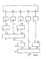
- three analog signals A 1 , A 2 ' A 3 are thus given. It can be the complex signals of different test frequencies or are linked signals.
- the analog signals A 1 , A 2 , A 3 are converted into the TTL signals T 1 , T 2 , T 3 by discriminators.
- the signals T 1 (or A 1 ) and T2 ( or A2 ) are used for fault detection.
- the signal T 1 has the task of indicating errors in the interference-free area or in the area with low interference (e.g. deposits, spacers, mit effect).
- T 2 is suitable for finding faults in the area of a type of disturbance with a large amplitude (e.g. rolling in).
- T 3 has the task of reporting the presence of this type of disturbance.
- the signals T 1 , T 2 and T 3 are then applied to the input of a TTL logic known per se and processed there according to the following truth table:
- the first signal is the amplitude level as a complex analog value and that the imaginary part of it is used for the threshold value comparison.
- the parameters of the z. B. generated as ALS or AH mix signals are chosen so that all disturbances on the pipe outer surface (spacer, baffle, flow distributor plate) are suppressed.
- the signal has a comparatively high test sensitivity and is used to find faults in the entire pipe, with the exception of rolling. Because of the high sensitivity, this leads to an incorrect error signal.
- a further embodiment of the invention is that the second signal is a complex analog value adapted to the expected disturbance variable, and that the ratio of the real part to the imaginary part is used for the threshold value comparison.
- the third signal is an impedance value measured with a suitable frequency and that the real part (X value) is used for the threshold value comparison.
- the logic in particular on the first channel, can be preceded by a delay element with an adjustable delay time.
- a timing element on the third channel can ensure that this signal is extended in time, so that in the area of the entire rolling (approx. 60 mm) there are well-defined conditions.
- a value for the ratio of the real part to the imaginary part corresponding to an error depth of 20% of the tube wall thickness is specified for the signal A 2 as the so-called angle threshold. If the threshold value is exceeded, the signal T 2 standardized to 5 V appears at output 9.
- the so-called X threshold 7 for the detection of a roll-in or a similarly strong disturbance speaks to the real part of the analog signal A 3 excited with 400 KHz.
- the threshold value for the normalized signal T 3 appearing at the output 10 is set so that the roll-in is reliably recognized in all cases.
- the output 8 is connected via a delay element 11 to the input 12 of a TTL logic 13.
- the delay time is approx. 25 ms corresponding to 5 mm pipe length.
- the output 9 leads directly to the input 14 of the TTL logic 13.
- the output 10 leads to a memory element 15 with which the signal T 3 is extended to a duration of approximately 250 ms, so that the input 16 of the TTL logic is acted upon by the X threshold 7 for at least 250 ms.
- the TTL logic 13 reports at its output 17 to which a data acquisition system, for. B. a magnetic tape or the like is connected, an error after linking the table above. This error is assigned to a pipe area in the data acquisition system, which is recorded via a path detection, not shown, of an eddy current probe, e.g. B. is entered via a time-dependent probe feed.
- a data acquisition system for. B. a magnetic tape or the like
- This error is assigned to a pipe area in the data acquisition system, which is recorded via a path detection, not shown, of an eddy current probe, e.g. B. is entered via a time-dependent probe feed.
- the output 17 of the upstream logic 13 is optionally connected to the input 21 of the downstream logic 22 via a delay element 20.
- the inputs 23 and 24 of the downstream logic 22 are then available at this point for recognizing a further type of fault and for finding faults.
- This The type of interferer can originate, for example, from the deposits known as dents.
- a signal A 4 of the equipment cabinet 1 is given to the input 23 via a threshold value generator 25.
- a 50 kHz analog signal comes as a signal A 5 via a threshold value transmitter 27 and a memory 28 with a 25 ms delay to the input 24.
- a data acquisition system is in turn connected to the output 29.
- the advantage of the invention is that an interferer can be detected precisely, regardless of an often inaccurate measurement of the coil location by the position sensor of the manipulator.
- the test area, in which the multi-frequency linkage suitable for this interferer is used, can be brought into exact congruence with the area of the interference display.
Landscapes
- Chemical & Material Sciences (AREA)
- Chemical Kinetics & Catalysis (AREA)
- Electrochemistry (AREA)
- Physics & Mathematics (AREA)
- Health & Medical Sciences (AREA)
- Life Sciences & Earth Sciences (AREA)
- Analytical Chemistry (AREA)
- Biochemistry (AREA)
- General Health & Medical Sciences (AREA)
- General Physics & Mathematics (AREA)
- Immunology (AREA)
- Pathology (AREA)
- Investigating Or Analyzing Materials By The Use Of Magnetic Means (AREA)
Applications Claiming Priority (2)
| Application Number | Priority Date | Filing Date | Title |
|---|---|---|---|
| DE3411898 | 1984-03-30 | ||
| DE19843411898 DE3411898A1 (de) | 1984-03-30 | 1984-03-30 | Verfahren zur pruefung von metallischen bauteilen, insbesondere kerntechnischer anlagen, mittels wirbelstrom |
Publications (3)
| Publication Number | Publication Date |
|---|---|
| EP0156020A2 true EP0156020A2 (fr) | 1985-10-02 |
| EP0156020A3 EP0156020A3 (en) | 1988-07-20 |
| EP0156020B1 EP0156020B1 (fr) | 1991-03-20 |
Family
ID=6232148
Family Applications (1)
| Application Number | Title | Priority Date | Filing Date |
|---|---|---|---|
| EP84115578A Expired - Lifetime EP0156020B1 (fr) | 1984-03-30 | 1984-12-17 | Procédé de contrôle de pièces métalliques, en particulier d'installations nucléaires, à l'aide de courants de Foucault |
Country Status (7)
| Country | Link |
|---|---|
| US (1) | US4687992A (fr) |
| EP (1) | EP0156020B1 (fr) |
| JP (1) | JPS60219550A (fr) |
| BR (1) | BR8501450A (fr) |
| DE (2) | DE3411898A1 (fr) |
| ES (1) | ES8900066A1 (fr) |
| FI (1) | FI84762C (fr) |
Cited By (1)
| Publication number | Priority date | Publication date | Assignee | Title |
|---|---|---|---|---|
| WO1993005391A1 (fr) * | 1991-09-02 | 1993-03-18 | Gemeinschaftskernkraftwerk Neckar Gmbh (Gkn) | Procede pour inspecter des tubes echangeurs de chaleur dans un echangeur thermique |
Families Citing this family (6)
| Publication number | Priority date | Publication date | Assignee | Title |
|---|---|---|---|---|
| US4763274A (en) * | 1986-06-24 | 1988-08-09 | Westinghouse Electric Corp. | Machine implemented analysis eddy current data |
| US5418456A (en) * | 1992-06-17 | 1995-05-23 | Westinghouse Electric Corporation | Monitoring pilger forming operation by sensing periodic lateral displacement of workpiece |
| FR2758882B1 (fr) * | 1997-01-27 | 1999-04-09 | Intercontrole Sa | Procede de controle non destructif, par courants de foucault, des grappes de commande de reacteurs nucleaires en presence d'elements perturbateurs |
| EP1952135A4 (fr) * | 2005-11-03 | 2011-12-14 | Coastal Res Corp | Réseau à courant de foucault convivial |
| US10896767B2 (en) | 2011-04-07 | 2021-01-19 | Westinghouse Electric Company Llc | Method of detecting an existence of a loose part in a steam generator of a nuclear power plant |
| DE102017209151A1 (de) * | 2017-05-31 | 2018-12-06 | Siemens Aktiengesellschaft | Vorrichtung und Verfahren zur zerstörungsfreien Prüfung eines Bauteils |
Family Cites Families (5)
| Publication number | Priority date | Publication date | Assignee | Title |
|---|---|---|---|---|
| US2992390A (en) * | 1956-06-18 | 1961-07-11 | Continental Oil Co | Method and apparatus for electrical testing of pipe |
| US3437810A (en) * | 1964-02-26 | 1969-04-08 | American Mach & Foundry | Non-destructive tubular goods inspection apparatus |
| US4061968A (en) * | 1976-09-07 | 1977-12-06 | Commissariat A L'energie Atomique | Process of and apparatus for non-destructive eddy current testing involves the suppression of displayed lobes corresponding to fault parameters to be eliminated from the display |
| US4325026A (en) * | 1979-03-19 | 1982-04-13 | Westinghouse Electric Corp. | Plural coil eddy current mapping probe |
| US4303885A (en) * | 1979-06-18 | 1981-12-01 | Electric Power Research Institute, Inc. | Digitally controlled multifrequency eddy current test apparatus and method |
-
1984
- 1984-03-30 DE DE19843411898 patent/DE3411898A1/de not_active Withdrawn
- 1984-12-17 EP EP84115578A patent/EP0156020B1/fr not_active Expired - Lifetime
- 1984-12-17 DE DE8484115578T patent/DE3484309D1/de not_active Expired - Lifetime
-
1985
- 1985-01-16 FI FI850197A patent/FI84762C/fi not_active IP Right Cessation
- 1985-03-27 JP JP60063156A patent/JPS60219550A/ja active Pending
- 1985-03-29 BR BR8501450A patent/BR8501450A/pt unknown
- 1985-03-29 US US06/717,888 patent/US4687992A/en not_active Expired - Fee Related
- 1985-03-29 ES ES541754A patent/ES8900066A1/es not_active Expired
Cited By (2)
| Publication number | Priority date | Publication date | Assignee | Title |
|---|---|---|---|---|
| WO1993005391A1 (fr) * | 1991-09-02 | 1993-03-18 | Gemeinschaftskernkraftwerk Neckar Gmbh (Gkn) | Procede pour inspecter des tubes echangeurs de chaleur dans un echangeur thermique |
| US5442284A (en) * | 1991-09-02 | 1995-08-15 | Gemeinschaftskernkraftwerk Neckar Gmbh | Process for inspecting spacers of heat exchanger tubes in a heat exchanger |
Also Published As
| Publication number | Publication date |
|---|---|
| EP0156020A3 (en) | 1988-07-20 |
| FI850197A0 (fi) | 1985-01-16 |
| FI850197L (fi) | 1985-10-01 |
| DE3484309D1 (de) | 1991-04-25 |
| BR8501450A (pt) | 1985-11-26 |
| FI84762B (fi) | 1991-09-30 |
| JPS60219550A (ja) | 1985-11-02 |
| FI84762C (fi) | 1992-01-10 |
| ES8900066A1 (es) | 1988-11-16 |
| EP0156020B1 (fr) | 1991-03-20 |
| ES541754A0 (es) | 1988-11-16 |
| DE3411898A1 (de) | 1985-10-10 |
| US4687992A (en) | 1987-08-18 |
Similar Documents
| Publication | Publication Date | Title |
|---|---|---|
| DE69637461T2 (de) | Überwachung von teilentladungen in leistungstransformatoren | |
| EP3379273B1 (fr) | Procédé, dispositif et système destinés à localiser un défaut sur une ligne d'un réseau d'alimentation électrique | |
| EP0092094B1 (fr) | Procédé et dispositif pour tester des matériaux selon le principe des courants de Foucault | |
| CN102565634B (zh) | 一种基于传递函数法的电力电缆故障定位方法 | |
| EP0023574B1 (fr) | Dispositif opto-électronique d'essai pour l'inspection automatique de la qualité de plaquettes à circuit imprimé, de leurs produits intermédiaires et des outils à imprimer | |
| DE3542159A1 (de) | Verfahren zur werkstoffpruefung nach dem wirbelstromprinzip und vorrichtung zur durchfuehrung des verfahrens | |
| CH640349A5 (de) | Verfahren zum auffinden und bestimmen eines fehlers eines rohres. | |
| DE19720708A1 (de) | Vorrichtung zum Untersuchen von Musterdefekten | |
| DE1932462A1 (de) | Verfahren und Vorrichtung zur Pruefung von Pipelines | |
| DE2841600B2 (de) | Verfahren und Vorrichtung zum Ermitteln von Korrosionsschäden in Rohren | |
| EP0596879B1 (fr) | Procede et dispositif de reconnaissance de defauts dans des systemes convertisseurs | |
| EP0156020B1 (fr) | Procédé de contrôle de pièces métalliques, en particulier d'installations nucléaires, à l'aide de courants de Foucault | |
| EP3282399A1 (fr) | Procede de reconnaissance ameliore d'anomalies de processus d'une installation technique et systeme de diagnostic correspondant | |
| DE102010006052B4 (de) | Verfahren und Systeme zum Testen von Digital-Analogwandler/Verstärkerschaltungen | |
| EP0082102B1 (fr) | Procédé pour la détection de tubes déflectueux avec gainage combustible à l'aide d'ultrasons | |
| EP0068503B1 (fr) | Méthode et dispositif d'essai de matériaux par le principe des courants de foucault | |
| DE2022151C3 (de) | Verfahren und Anordnung zur Fehlervermeidung bei inkrementalen Meßsystemen | |
| DE3135969C2 (de) | Ultraschallprüfverfahren zum Nachweis von Ungänzen in Werkstücken und Ultraschallprüfgerät mit einer Blendenschaltung zur Durchführung des Verfahrens | |
| DE2720804A1 (de) | Verfahren zur materialpruefung | |
| DE19513194C1 (de) | Verfahren und Vorrichtung zur Erfassung von Ungänzen an langgestreckten Werkstücken, insbesondere Rohre und Stangen | |
| EP4030622A1 (fr) | Unité inductive de détection de proximité et procédé de détection des dysfonctionnements de l'unité inductive de détection de proximité | |
| DE3034426A1 (de) | Anordnung zur zerstoerungsfreien pruefung von elektrisch leitfaehigen werkstoffen auf der grundlage des impuls-wirbelstromverfahrens | |
| DE4318511C2 (de) | Verfahren zum Erfassen eines Startsignals eines Geisterbildunterdrückungsreferenzsignales und dazugehöriger Schaltkreis | |
| DE3008924A1 (de) | Verfahren zur automatischen einstellung einer vielzahl gleichartiger messkanaele von ultraschallanlagen | |
| DE3733040C2 (fr) |
Legal Events
| Date | Code | Title | Description |
|---|---|---|---|
| PUAI | Public reference made under article 153(3) epc to a published international application that has entered the european phase |
Free format text: ORIGINAL CODE: 0009012 |
|
| AK | Designated contracting states |
Designated state(s): CH DE FR IT LI NL SE |
|
| RAP1 | Party data changed (applicant data changed or rights of an application transferred) |
Owner name: SIEMENS AKTIENGESELLSCHAFT |
|
| PUAL | Search report despatched |
Free format text: ORIGINAL CODE: 0009013 |
|
| AK | Designated contracting states |
Kind code of ref document: A3 Designated state(s): CH DE FR IT LI NL SE |
|
| 17P | Request for examination filed |
Effective date: 19890120 |
|
| 17Q | First examination report despatched |
Effective date: 19900226 |
|
| GRAA | (expected) grant |
Free format text: ORIGINAL CODE: 0009210 |
|
| AK | Designated contracting states |
Kind code of ref document: B1 Designated state(s): CH DE FR IT LI NL SE |
|
| PG25 | Lapsed in a contracting state [announced via postgrant information from national office to epo] |
Ref country code: SE Effective date: 19910320 Ref country code: NL Effective date: 19910320 Ref country code: IT Free format text: LAPSE BECAUSE OF FAILURE TO SUBMIT A TRANSLATION OF THE DESCRIPTION OR TO PAY THE FEE WITHIN THE PRESCRIBED TIME-LIMIT;WARNING: LAPSES OF ITALIAN PATENTS WITH EFFECTIVE DATE BEFORE 2007 MAY HAVE OCCURRED AT ANY TIME BEFORE 2007. THE CORRECT EFFECTIVE DATE MAY BE DIFFERENT FROM THE ONE RECORDED. Effective date: 19910320 |
|
| REF | Corresponds to: |
Ref document number: 3484309 Country of ref document: DE Date of ref document: 19910425 |
|
| EN | Fr: translation not filed | ||
| PG25 | Lapsed in a contracting state [announced via postgrant information from national office to epo] |
Ref country code: FR Effective date: 19910809 |
|
| NLV1 | Nl: lapsed or annulled due to failure to fulfill the requirements of art. 29p and 29m of the patents act | ||
| PG25 | Lapsed in a contracting state [announced via postgrant information from national office to epo] |
Ref country code: LI Effective date: 19911231 Ref country code: CH Effective date: 19911231 |
|
| PLBI | Opposition filed |
Free format text: ORIGINAL CODE: 0009260 |
|
| 26 | Opposition filed |
Opponent name: ABB PATENT GMBH Effective date: 19911218 |
|
| REG | Reference to a national code |
Ref country code: CH Ref legal event code: PL |
|
| REG | Reference to a national code |
Ref country code: FR Ref legal event code: ST |
|
| PLBN | Opposition rejected |
Free format text: ORIGINAL CODE: 0009273 |
|
| STAA | Information on the status of an ep patent application or granted ep patent |
Free format text: STATUS: OPPOSITION REJECTED |
|
| 27O | Opposition rejected |
Effective date: 19940218 |
|
| PGFP | Annual fee paid to national office [announced via postgrant information from national office to epo] |
Ref country code: DE Payment date: 20020218 Year of fee payment: 18 |
|
| PG25 | Lapsed in a contracting state [announced via postgrant information from national office to epo] |
Ref country code: DE Free format text: LAPSE BECAUSE OF NON-PAYMENT OF DUE FEES Effective date: 20030701 |