EP0156026A2 - Dispositif d'enlèvement et de fixation pour toits d'automobiles - Google Patents
Dispositif d'enlèvement et de fixation pour toits d'automobiles Download PDFInfo
- Publication number
- EP0156026A2 EP0156026A2 EP84115794A EP84115794A EP0156026A2 EP 0156026 A2 EP0156026 A2 EP 0156026A2 EP 84115794 A EP84115794 A EP 84115794A EP 84115794 A EP84115794 A EP 84115794A EP 0156026 A2 EP0156026 A2 EP 0156026A2
- Authority
- EP
- European Patent Office
- Prior art keywords
- guide
- motor vehicle
- roof
- holding member
- guide carriage
- Prior art date
- Legal status (The legal status is an assumption and is not a legal conclusion. Google has not performed a legal analysis and makes no representation as to the accuracy of the status listed.)
- Granted
Links
Images


Classifications
-
- B—PERFORMING OPERATIONS; TRANSPORTING
- B66—HOISTING; LIFTING; HAULING
- B66C—CRANES; LOAD-ENGAGING ELEMENTS OR DEVICES FOR CRANES, CAPSTANS, WINCHES, OR TACKLES
- B66C1/00—Load-engaging elements or devices attached to lifting or lowering gear of cranes or adapted for connection therewith for transmitting lifting forces to articles or groups of articles
- B66C1/10—Load-engaging elements or devices attached to lifting or lowering gear of cranes or adapted for connection therewith for transmitting lifting forces to articles or groups of articles by mechanical means
- B66C1/62—Load-engaging elements or devices attached to lifting or lowering gear of cranes or adapted for connection therewith for transmitting lifting forces to articles or groups of articles by mechanical means comprising article-engaging members of a shape complementary to that of the articles to be handled
- B66C1/66—Load-engaging elements or devices attached to lifting or lowering gear of cranes or adapted for connection therewith for transmitting lifting forces to articles or groups of articles by mechanical means comprising article-engaging members of a shape complementary to that of the articles to be handled for engaging holes, recesses, or abutments on articles specially provided for facilitating handling thereof
Definitions
- the invention relates to a device for holding a removable motor vehicle roof on the ceiling of a building, in particular a garage.
- the object of the invention is therefore to provide a device for holding a removable motor vehicle roof on the ceiling of a building, in particular a garage, by means of which it is possible in a very simple manner and in a short time to remove or open the roof of a motor vehicle from it to put this on without requiring several people. Furthermore, damage to the vehicle body and the roof should be largely avoided and this should also be kept safely on the ceiling of the garage.
- the guide carriage from two integral or multi-part bars arranged at a lateral distance from one another and rigidly connected to one another, in which the guide member and the holding member are adjustably mounted, wherein the bars should be arranged on a plate.
- the guide carriage cannot be moved easily, with one with the guide member and / or with one with the holding member cooperating braking device to provide, for example, in the form of an adjustable clamping ring and to limit its displacement by adjusting rings arranged on the guide or holding member.
- the holding member can be produced in a simple manner from two rods which are arranged so as to be displaceable at a lateral spacing in the spars of the guide carriage and from these at the ends of cross tubes which connect to one another and on which levers which can be coupled in pairs to the motor vehicle roof are preferably pivotably mounted to a limited extent.
- the levers of the holding member should be held pivotably on bolts arranged parallel to the cross tubes, which are mounted in base plates attached to the cross tubes, the adjustment path being limited by stops attached to the base plate, preferably each formed by a bent stop plate.
- the levers should each be held in the open position by the force of a spring which is preferably supported on this and one of the stops and should be provided at its free end with a hook engaging behind the rain gutter of the motor vehicle roof and an eccentric cam which can be inserted into it.
- G for the vertical adjustment of the guide carriage supporting guide song is to provide suitably an axis extending parallel to this driven threaded spindle and oppositely arranged carrying arms each adjustable guided with one end on the equipped with oppositely threaded screw spindle and with the other end to the guide member preferably on its Cross bars connecting rods are articulated.
- the support arms it is appropriate to support the support arms on one or both sides on rails arranged next to the threaded spindle above them on rolling ball bearings, rollers or the like, and to guide them by means of articulated support levers which are held in a pivoted manner, these being in the middle of the preferably fork-shaped support arms to be linked to these.
- the support arms should be designed as lattice girders with connecting webs inserted between lateral struts supported on the guide slide and via a nut on the threaded spindle.
- the threaded spindle and the running rails should be supported at least in the end regions by cross struts and / or support plates, and the cross struts can also be held in a height-adjustable manner by means of threaded spindles attached to a mounting plate.
- the device designed according to the invention for holding a removable motor vehicle roof on the ceiling of a building, in particular a garage is not only very simple in terms of construction and thus economical to manufacture, but also makes it possible to easily remove a motor vehicle roof from just one person or to place on the motor vehicle without having to accept damage, so that a changeover can be accomplished in a very short time with simple handling.
- Is namely arranged on a vertically adjustable Guide member is a horizontally slidably mounted slide, in which a holding member is movably inserted, which is to be connected to the motor vehicle roof, so that there is displacement in two directions, the holding member can be aligned to the motor vehicle without difficulty. Removing or putting on a motor vehicle roof is therefore easy to accomplish, in fact only one person is required for this, since the height of the guide members can be adjusted with the aid of a drive motor.
- the roof which is always hung horizontally, can be safely stored under the ceiling of the garage, so that no other usable space is used, and the suspension on the garage ceiling guarantees that damage is almost impossible.
- the device designed according to the invention thus enables a motor vehicle to be converted for a short time, even by an inexperienced person, especially since the lever linkage provided can be used to lower it in a careful manner.
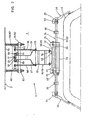
- the device shown in FIGS. 1 and 2 and designated 11 serves to hold a removable Dashes 3 of a motor vehicle and is attached to the ceiling 2 of a garage 1 to remove the roof 3 from the motor vehicle or put it on and below the To be able to store garage ceiling 2.
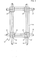
- the guide carriage 12 is formed from two two-part spars 21, 21 'and 22, 22' fixedly arranged on a platform 23, in which bores 24 and 24 'as well as 25 and 25' are incorporated, in which the rods 26 and 27 are made Guide member 13 and the holding member 14 also having stands 31 and 32 are adjustably mounted.
- the rods 26 and 27 of the guide member 1-3 and the rods 31 and 32 of the holding member 14 are each firmly connected to one another by transverse tubes 28 and 29 or 33 and 34 and are perpendicular to one another.
- pivotally mounted levers 36 are provided, which have a hook 43 at their free end, which engages under the gutter 4 of the roof 3 and with this can be clamped with the aid of an eccentric cam 44 which can be inserted into it and actuated by means of a handle 45.
- the lever 36 is in each case pivotably mounted on a pin 37 which projects from a base plate 35 attached to the cross tubes 33 and 34.
- two stops 39 and 40 formed by a stop plate 38 are provided to limit the adjustment path of the lever 36.
- a spring 42 which is inserted into a bore 41 machined in the lever 36 and is supported on the stop 39, the lever 36 is always held in the open position.
- the support arms 15 and 16 are articulated at one end by means of bolts 54 in bearings 53 attached to the transverse tubes 28 and 29, and at the other end by means of bolts 56 are articulated to nuts 55 which are seated on the threaded spindle 17 equipped with opposing threads.
- the support arms 15 and 16 which are constructed as lattice girders and are composed of outer struts 51 and 51 'and of transverse webs 52, are displaced with the upper end inwards or outwards, so that the guide carriage 12 and the holding member connected to it 14 raised or lowered.
- 17 guide rails 64 and 65 are provided on both sides of the threaded spindle, on which the nuts 55 are supported by means of ball bearings 57 or rollers arranged on the bolts 56.
- support arms 58 and 58 ' are articulated by means of bolts 59 on the support arms 15 and 16, which are articulated by means of further bolts 60 on plates 66 and 67, on which the threaded spindle 17 and the running rails 64 and 65 are supported.
- struts 61, 62 and 63 are used, which are penetrated by threaded rods 68.
- the struts 61, 62 and 63 are held on the threaded rods 68 by means of nuts 69, which protrude from mounting plates 7o fastened to the ceiling 2 of the garage 1.
- the rails 64 and 65 are further supported by a plate 71 on which a bearing 72 for the threaded spindle 17 is also arranged.
- the roof 2 can be raised by switching on the drive motor 18 and hung under the ceiling 2 of the garage 1 . Since the guide carriage 12 on the rods 26 and 27 in their axial direction and the holding member 14 by means of the in the spars 21, 21 'and 22, 22' Guided rods 31 and 32 can be moved in another, perpendicular direction, the levers 36 can be quickly and easily brought into a position in which they can be clamped to the roof 3.
- the threaded spindle 17 is driven in such a way that the nuts 55 are moved inward on the opposite threads in the direction of the bearing 72, the roof 3 is raised in a horizontal position and can be in a limit position determined by a limit switch 73 of the guide member 13 are kept without causing damage.
- the support arms 15 and 16 are always stabilized by the support levers 58, 58 '. If the threaded spindle 17 is driven in the opposite direction, the roof 3 is lowered. Here too, the adjustment path of the support arms 15 and 16 is limited by a limit switch 74.
Landscapes
- Engineering & Computer Science (AREA)
- Mechanical Engineering (AREA)
- Vehicle Cleaning, Maintenance, Repair, Refitting, And Outriggers (AREA)
- Conveying And Assembling Of Building Elements In Situ (AREA)
- Control And Other Processes For Unpacking Of Materials (AREA)
- Load-Engaging Elements For Cranes (AREA)
- Tents Or Canopies (AREA)
Priority Applications (1)
| Application Number | Priority Date | Filing Date | Title |
|---|---|---|---|
| AT84115794T ATE37853T1 (de) | 1984-03-28 | 1984-12-19 | Abnahme- und haltevorrichtung fuer autodaecher. |
Applications Claiming Priority (2)
| Application Number | Priority Date | Filing Date | Title |
|---|---|---|---|
| DE19843411345 DE3411345A1 (de) | 1984-03-28 | 1984-03-28 | Abnahme- und haltevorrichtung fuer autodaecher |
| DE3411345 | 1984-03-28 |
Publications (3)
| Publication Number | Publication Date |
|---|---|
| EP0156026A2 true EP0156026A2 (fr) | 1985-10-02 |
| EP0156026A3 EP0156026A3 (en) | 1986-10-22 |
| EP0156026B1 EP0156026B1 (fr) | 1988-10-12 |
Family
ID=6231811
Family Applications (1)
| Application Number | Title | Priority Date | Filing Date |
|---|---|---|---|
| EP84115794A Expired EP0156026B1 (fr) | 1984-03-28 | 1984-12-19 | Dispositif d'enlèvement et de fixation pour toits d'automobiles |
Country Status (3)
| Country | Link |
|---|---|
| EP (1) | EP0156026B1 (fr) |
| AT (1) | ATE37853T1 (fr) |
| DE (2) | DE3411345A1 (fr) |
Cited By (6)
| Publication number | Priority date | Publication date | Assignee | Title |
|---|---|---|---|---|
| US5795118A (en) * | 1994-09-12 | 1998-08-18 | Nifco, Inc. | Tacking device |
| WO2008124019A1 (fr) | 2007-04-04 | 2008-10-16 | Carter Mark C | Stockage modulaire en garage |
| CN106256756A (zh) * | 2016-09-26 | 2016-12-28 | 徐州和胜重工有限公司 | 平行多杆同步驱动栏杆升降机构 |
| CN112209291A (zh) * | 2020-10-23 | 2021-01-12 | 江苏印象乾图文化科技有限公司 | 一种屏幕联动组装用防护装置 |
| CN114319970A (zh) * | 2022-01-13 | 2022-04-12 | 北京畅停天下停车场服务有限公司 | 一种私家车泊车机 |
| CN116621022A (zh) * | 2023-03-10 | 2023-08-22 | 中国第一汽车股份有限公司 | 一种用于汽车生产线的双轨平衡零部件吊运装置 |
Families Citing this family (3)
| Publication number | Priority date | Publication date | Assignee | Title |
|---|---|---|---|---|
| DE4238346A1 (de) * | 1992-11-13 | 1994-05-26 | Rainer Lutz | Vorrichtung zum Verstauen des Hardtops eines Cabrios |
| EP4403130A1 (fr) * | 2023-01-17 | 2024-07-24 | Ondal Medical Systems GmbH | Dispositif de bras de ressort et système de bras de support pour maintenir un appareil médical |
| CN116730166A (zh) * | 2023-08-01 | 2023-09-12 | 江苏同和智能装备有限公司 | 一种汽车总装线用汽车底盘浮动吊具及其驱动控制系统 |
Family Cites Families (3)
| Publication number | Priority date | Publication date | Assignee | Title |
|---|---|---|---|---|
| US1725216A (en) * | 1926-12-30 | 1929-08-20 | Anthony Marietta | Automobile jack |
| DE7514743U (de) * | 1975-05-07 | 1975-11-20 | Sawatzki H | Hebeeinrichtung fuer hardtops |
| DE8409447U1 (de) * | 1984-03-28 | 1984-11-22 | Wisker, Dieter, 7758 Daisendorf | Abnahme- und haltevorrichtung fuer autodaecher |
-
1984
- 1984-03-28 DE DE19843411345 patent/DE3411345A1/de not_active Withdrawn
- 1984-12-19 DE DE8484115794T patent/DE3474541D1/de not_active Expired
- 1984-12-19 EP EP84115794A patent/EP0156026B1/fr not_active Expired
- 1984-12-19 AT AT84115794T patent/ATE37853T1/de not_active IP Right Cessation
Cited By (8)
| Publication number | Priority date | Publication date | Assignee | Title |
|---|---|---|---|---|
| US5795118A (en) * | 1994-09-12 | 1998-08-18 | Nifco, Inc. | Tacking device |
| WO2008124019A1 (fr) | 2007-04-04 | 2008-10-16 | Carter Mark C | Stockage modulaire en garage |
| US8162159B2 (en) | 2007-04-04 | 2012-04-24 | Carter Mark C | Modular garage storage |
| CN106256756A (zh) * | 2016-09-26 | 2016-12-28 | 徐州和胜重工有限公司 | 平行多杆同步驱动栏杆升降机构 |
| CN106256756B (zh) * | 2016-09-26 | 2018-06-22 | 徐州和胜重工有限公司 | 平行多杆同步驱动栏杆升降机构 |
| CN112209291A (zh) * | 2020-10-23 | 2021-01-12 | 江苏印象乾图文化科技有限公司 | 一种屏幕联动组装用防护装置 |
| CN114319970A (zh) * | 2022-01-13 | 2022-04-12 | 北京畅停天下停车场服务有限公司 | 一种私家车泊车机 |
| CN116621022A (zh) * | 2023-03-10 | 2023-08-22 | 中国第一汽车股份有限公司 | 一种用于汽车生产线的双轨平衡零部件吊运装置 |
Also Published As
| Publication number | Publication date |
|---|---|
| EP0156026A3 (en) | 1986-10-22 |
| DE3411345A1 (de) | 1985-10-10 |
| EP0156026B1 (fr) | 1988-10-12 |
| ATE37853T1 (de) | 1988-10-15 |
| DE3474541D1 (en) | 1988-11-17 |
Similar Documents
| Publication | Publication Date | Title |
|---|---|---|
| DE19901496C1 (de) | Klemmgreifer für von oben zu greifende Lasten | |
| EP0501254B1 (fr) | Table élévatrice à ciseaux | |
| EP0034221B1 (fr) | Plateforme à tréteau déplaçable en hauteur pour scènes de théâtre ou analogues | |
| EP0173180A1 (fr) | Dispositif de basculement ou de soulèvement/basculement pour le vidage de récipients dans des récipients collecteurs, plus spécialement de poubelles dans le récipient collecteur d'un camion de voirie | |
| EP0339235A2 (fr) | Table avec plateau basculant et réglable en hauteur | |
| EP0156026B1 (fr) | Dispositif d'enlèvement et de fixation pour toits d'automobiles | |
| DE69408471T2 (de) | Vorrichtung zum stellen einer glasscheibe für einen laden | |
| DE2906712A1 (de) | Richtbank fuer fahrzeugrahmen | |
| DE2049211C3 (de) | Greifvorrichtung für Bauteile | |
| DE2751085A1 (de) | Sperrvorrichtung an saeulenheber | |
| DE8706196U1 (de) | Winkelschraubstock | |
| DD257236A5 (de) | Stapelbehaelter fuer formteile | |
| DE3248937T1 (de) | Halterungs- und Abstützvorrichtung | |
| WO1986003179A1 (fr) | Procede et installation pour amarrer a une surface portante fixe un element de support formant surface portante | |
| EP0314916B1 (fr) | Table de plantes pour entreprises horticoles | |
| DE1290900B (de) | Werkzeugwagen, insbesondere fuer Reparaturwerkstaetten | |
| DE69202121T2 (de) | Anlage zur Querversetzung von untereinanderverbundenen Strassenleiteinrichtungselementen. | |
| DE3835551A1 (de) | Wasserfahrzeug | |
| AT410913B (de) | Auflagetisch für eine trennsäge mit einem maschinentisch | |
| DE3446523A1 (de) | Wagenheber | |
| DE8409447U1 (de) | Abnahme- und haltevorrichtung fuer autodaecher | |
| DE2304864A1 (de) | Gleitformeinrichtung bzw. gleitschalung zum giessen eines betonkoerpers | |
| DE2620528C3 (de) | Vorrichtung zum Spannen von Walzgut im Arbeitsbereich eines Trennwerkzeuges, insbesondere eines Kreissägeblattes | |
| AT349049B (de) | Schienenheber | |
| DE2910097C2 (de) | Vorrichtung zum Fräsen von Entwässerungsschlitzen in ein Fensterprofil |
Legal Events
| Date | Code | Title | Description |
|---|---|---|---|
| PUAI | Public reference made under article 153(3) epc to a published international application that has entered the european phase |
Free format text: ORIGINAL CODE: 0009012 |
|
| AK | Designated contracting states |
Designated state(s): AT BE CH DE FR GB IT LI LU NL SE |
|
| PUAL | Search report despatched |
Free format text: ORIGINAL CODE: 0009013 |
|
| AK | Designated contracting states |
Kind code of ref document: A3 Designated state(s): AT BE CH DE FR GB IT LI LU NL SE |
|
| 17P | Request for examination filed |
Effective date: 19861205 |
|
| 17Q | First examination report despatched |
Effective date: 19870827 |
|
| GRAA | (expected) grant |
Free format text: ORIGINAL CODE: 0009210 |
|
| AK | Designated contracting states |
Kind code of ref document: B1 Designated state(s): AT BE CH DE FR GB IT LI LU NL SE |
|
| PG25 | Lapsed in a contracting state [announced via postgrant information from national office to epo] |
Ref country code: SE Effective date: 19881012 Ref country code: NL Effective date: 19881012 Ref country code: IT Free format text: LAPSE BECAUSE OF FAILURE TO SUBMIT A TRANSLATION OF THE DESCRIPTION OR TO PAY THE FEE WITHIN THE PRESCRIBED TIME-LIMIT;WARNING: LAPSES OF ITALIAN PATENTS WITH EFFECTIVE DATE BEFORE 2007 MAY HAVE OCCURRED AT ANY TIME BEFORE 2007. THE CORRECT EFFECTIVE DATE MAY BE DIFFERENT FROM THE ONE RECORDED. Effective date: 19881012 Ref country code: GB Free format text: LAPSE BECAUSE OF NON-PAYMENT OF DUE FEES Effective date: 19881012 Ref country code: FR Free format text: THE PATENT HAS BEEN ANNULLED BY A DECISION OF A NATIONAL AUTHORITY Effective date: 19881012 Ref country code: BE Effective date: 19881012 |
|
| REF | Corresponds to: |
Ref document number: 37853 Country of ref document: AT Date of ref document: 19881015 Kind code of ref document: T |
|
| REF | Corresponds to: |
Ref document number: 3474541 Country of ref document: DE Date of ref document: 19881117 |
|
| PG25 | Lapsed in a contracting state [announced via postgrant information from national office to epo] |
Ref country code: LU Free format text: LAPSE BECAUSE OF NON-PAYMENT OF DUE FEES Effective date: 19881231 |
|
| EN | Fr: translation not filed | ||
| NLV1 | Nl: lapsed or annulled due to failure to fulfill the requirements of art. 29p and 29m of the patents act | ||
| GBV | Gb: ep patent (uk) treated as always having been void in accordance with gb section 77(7)/1977 [no translation filed] | ||
| PLBE | No opposition filed within time limit |
Free format text: ORIGINAL CODE: 0009261 |
|
| STAA | Information on the status of an ep patent application or granted ep patent |
Free format text: STATUS: NO OPPOSITION FILED WITHIN TIME LIMIT |
|
| 26N | No opposition filed | ||
| PGFP | Annual fee paid to national office [announced via postgrant information from national office to epo] |
Ref country code: AT Payment date: 19941222 Year of fee payment: 11 |
|
| PGFP | Annual fee paid to national office [announced via postgrant information from national office to epo] |
Ref country code: CH Payment date: 19950318 Year of fee payment: 11 |
|
| PG25 | Lapsed in a contracting state [announced via postgrant information from national office to epo] |
Ref country code: AT Effective date: 19951219 |
|
| PG25 | Lapsed in a contracting state [announced via postgrant information from national office to epo] |
Ref country code: LI Effective date: 19951231 Ref country code: CH Effective date: 19951231 |
|
| REG | Reference to a national code |
Ref country code: CH Ref legal event code: PL |
|
| PGFP | Annual fee paid to national office [announced via postgrant information from national office to epo] |
Ref country code: DE Payment date: 20000823 Year of fee payment: 16 |
|
| PG25 | Lapsed in a contracting state [announced via postgrant information from national office to epo] |
Ref country code: DE Free format text: LAPSE BECAUSE OF NON-PAYMENT OF DUE FEES Effective date: 20011002 |