EP0156041A1 - Presse pour mise en balles cylindriques - Google Patents
Presse pour mise en balles cylindriques Download PDFInfo
- Publication number
- EP0156041A1 EP0156041A1 EP84201718A EP84201718A EP0156041A1 EP 0156041 A1 EP0156041 A1 EP 0156041A1 EP 84201718 A EP84201718 A EP 84201718A EP 84201718 A EP84201718 A EP 84201718A EP 0156041 A1 EP0156041 A1 EP 0156041A1
- Authority
- EP
- European Patent Office
- Prior art keywords
- arm assembly
- bale
- movable frame
- bale forming
- frame
- Prior art date
- Legal status (The legal status is an assumption and is not a legal conclusion. Google has not performed a legal analysis and makes no representation as to the accuracy of the status listed.)
- Granted
Links
Images


Classifications
-
- A—HUMAN NECESSITIES
- A01—AGRICULTURE; FORESTRY; ANIMAL HUSBANDRY; HUNTING; TRAPPING; FISHING
- A01F—PROCESSING OF HARVESTED PRODUCE; HAY OR STRAW PRESSES; DEVICES FOR STORING AGRICULTURAL OR HORTICULTURAL PRODUCE
- A01F15/00—Baling presses for straw, hay or the like
- A01F15/07—Rotobalers, i.e. machines for forming cylindrical bales by winding and pressing
- A01F15/0705—Arrangements for continuous operation
Definitions
- This invention relates generally to the type of roll baling machine that comprises an expandable bale forming chamber and is described in particular with reference to a roll baling machine that is capable of continuously forming roll bales of crop material while moving across a field without stopping to discharge such bales.
- U.S. Patent No. 4,035,999 assigned to the same assignee as the present application.
- the disclosed machine includes a lower apron and a pair of upper aprons.
- the upper aprons cooperate with the lower apron to define front and rear bale forming chambers. While a completed roll bale is being wrapped with twine and discharged from the rear chamber, another bale is started in the front chamber. When the bale started in the front chamber reaches a predetermined size, it is transferred to the rear chamber where it is completed. This provides for continuous baling operation of the machine.
- Such roll baling machines of the type having an expandable bale forming chamber normally have a base frame and a movable frame connected thereto for movement between a closed position for bale formation and an open position for bale discharge.
- Such machines also may have an arm assembly adjustably supported on the movable frame for movably supporting, at least in part, bale forming means which, preferably but not necessarily, are of the apron or belt type.
- the bale forming means may be of the roller type such as shown e.g. in DE. 24.43.838.
- the arm assembly may be movable outwardly during formation of a roll bale in the bale forming chamber from an inward position assumed when the bale forming chamber is empty.
- Coil springs or other resilient means may be provided for normally urging the arm assembly toward the inward position.
- a drawback of such machines is that, when the movable frame is pivoted upwardly for discharging a completed bale, the arm assembly tends to move towards its inward position with respect to the movable frame, whereby it might interfere, not only with the opening and closing of the rear frame, but also with the discharge of the bale from the bale forming chamber.
- a roll baling machine of the type having an expandable bale forming chamber which com ⁇ rises : - a base frame; - a movable or rear frame connected to the base frame for movement between a closed position and an open position; - an arm assembly adjustably supported on the movable frame and movable outwardly during formation of a roll bale in the bale forming chamber from an inward position assumed when the bale forming chamber is empty; - and bale forming means movably supported at least in part on the arm assembly.
- control means are provided for holding the arm assembly in an outward position as the movable frame is moved to its open position for discharging a bale from the bale forming chamber.
- the bale forming means are in the form of expandable apron means movably supported at least in part on guide means provided on the arm assembly.
- the bale forming means may be of the roller type and be rotatably mounted on the arm assembly.
- Resilient means preferably in the form of tension springs, are provided for normally urging the arm assembly toward the inward position.
- Actuator means in the form of hydraulic cylinders are provided between the main frame and the movable frame for moving the movable frame from its closed position to its open position and vice-versa.
- the control means are operably coupled to the actuator means in a manner to allow the arm assembly, when the movable frame is in the closed position, to move between the inward and outward positions, and, when the movable frame is in the open position, to restrain the arm assembly to the outward position.
- control means comprise a linkage means including a link member having a lost-motion connection with the arm assembly as the arm assembly moves between the inward and outward positions when the movable frame is in the closed position.
- the lost-motion connection may consist of said link member having an elongated slot formed therein for slidably receiving a pin mounted on the ar8 assembly.
- the invention is equally applicable on the commonly known single chamber roll baling machines and on the continuous roll baling machines such as those of the type having first and second bale forming chambers.
- a roll baling machine 10 includes a base frame 12 supported at its sides by wheels 14 and adapted for connection to a tractor (not shown) by a tongue 16.
- a pickup device 18 and a lower apron 20 are supported on the base frame 12.
- the lower apron 20 is preferably of the type disclosed in U.S. Patent No. 3,901,007, incorporated herein by reference.
- a rear frame 22 is pivotally connected at 24 to the base frame 12.
- a first upper bale forming apron 26 is movably supported on guide members 28,30,32,34,36,38,40,42 carried on the opposite sides of the base frame 12 and on guide members 44,46,48 carried at the opposite sides of the rear frame 22.
- the upper course 20a of the lower apron 20 cooperates with a course 26a of the first upper apron 26 extending between the guide members 28 and 40 to define an expandable front bale chamber 50.
- a second upper bale forming apron 52 is movably supported on guide members 54,56,58,60,62 carried at the opposite sides of the rear frame 22.
- a course 52a of the second upper apron 52 extending between the guide members 54 and 62 cooperates with a course 26b of the first upper apron 26 extending between the guide members 40 and 48 to define an expandable rear bale chamber 64.
- the rear part of the lower apron 20 and a roller 65 are disposed at the bottom of th rear bale chamber 64.
- the first and second upper aprons 26 and 52 are preferably formed of a pair of endless link-type chains connected at spaced intervals by transverse bars or slats such as the upper apron disclosed in U.S. Patent No.
- the guide members 42 are of the cam type also disclosed in this patent.
- the front and rear bale chambers 50, 64 when in the empty condition, are generally triangular in shape with the front bale chamber 50 being oriented generally horizontally and with the rear bale chamber 64 extending in a generally upright orientation.
- a series of ramps 66 are carried on the base frame 12 and extend transversely between the opposite sides thereof. These ramps 66 are pivotally movable and are similar to those disclosed in U.S. Patent No. 4,035,999, incorporated herein by reference, and designated therein by the numeral "282".
- the guide members 40 are carried by a pair of arms 68 which are pivotally movable on shafts 70 secured to the base frame 12. Hydraulic cylinders 72 control the pivotal movement of the arms 68, and slots 74 formed in the sides of the base frame 12 limit and guide the upward and downward movement of the guide members 40.
- An actuator mechanism 76 interconnects the arms 68 and the ramps 66.
- the guide members 34 and 36 are movable fore and aft in channels 78 and 80, respectively, mounted on the base frame 12. Idler mechanisms 82 control the movement of the guide members 34 in the channel 78. Springs 84 are connected to the guide members 36 by cables or chains 86 to urge the guide members 36 forward in the channels 80 to thus provide tension in the apron 26.
- Hydraulic cylinders 88 are connected between the base frame 12 and frame members 13 ( Figures 9-11) of the rear frame 22 for moving the rear frame 22 between the closed position shown in Fig. 1 and the open position shown in Fig.. 8.
- the guide members 44,46,48,54 and 60 are carried on an arm assembly 90 that is pivoted at 92 on the rear frame 22.
- Springs 94 are connected to lever portions 96 of the arm assembly 90 to urge the arm assembly 90 in a counterclockwise direction about the pivot 92 when viewed in Fig. 1.
- the guide members 56 and 58 are carried on another arm assembly 98 that is also pivoted at 92 on the rear frame 22.
- Springs 100 are connected to lever portions 102 of the arm assembly 98 to urge the arm assembly 98 in a clockwise direction about the pivot 92 when viewed in Fig. 1.
- Springs 94 are stronger than springs 100.
- a control linkage 104 is connected between the rear frame 22 and other lever portions 106 of the arm assembly 90 to pull the arm assembly 90 in a clockwise direction against the springs 94 when viewed in Fig. 1, during movement of the rear frame 22 to the open position of Fig. 8.
- the pickup device 18 delivers crop material into the front bale chamber 50 where it is coiled by the cooperating movement of the lower apron 20 and the upper apron 26 (as indicated in Fig. 1) to start the core of a roll bale.
- the guide members 40 are in their lowermost position in the slots 74 and the ramps 66 are pivoted upwardly to extend through and above the upper course 20a of the lower apron 20 so that the upper apron 26 and the ramps 66 together close the rear of the front bale chamber 50 and thereby effectively prevent material from entering the rear bale chamber 64.
- the guide members 36 move rearwardly in the channels 80 against the force of the spring 84. This allows the course 26a of the apron 26 that extends between the guide members 28 and 40 to expand around the bale.
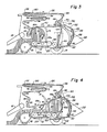
- the guide members 40 When the bale reaches a predetermined diameter, the guide members 40 are moved upwardly in the slots 74, as shown in Fig. 3, by contracting the hydraulic cylinders 72 in order to pivot the arms 68 upwardly on the shafts 70.
- the guide members 36 are moved forwardly in the channels 80 by the springs 84 to take up the slack in the apron 26 resulting from the movement of the guide members 40 to their uppermost positions in the slots 74.
- the actuator mechanism 76 connecting the arms 68 and the ramps 66 causes downward pivoting movement of the ramps 66 simultaneously with the upward movement of the guide members 40.
- the ramps 66 are pivoted downwardly below the upper course 20a of the lower apron 20.
- the bale is then transferred by the lower apron 20 into the rear bale chamber 64, as shown in Fig. 4, where it rests primarily on the roller 65.
- the apron 26 is either stopped or driven in reverse direction.
- the guide members 40 are moved downwardly in the slots 74 to an intermediate position by extending the hydraulic cylinders 72 in order to pivot the arms 68 downwardly about the shafts 70. In this intermediate position of the guide members 40, the course 26a of the apron 26 that extends between the guide members 28 and 40 is supported slightly by the guide members 42.
- the course 26b of the apron 26 that extends between the guide members 40 and 48 expands around a forward upper portion of the bale to maintain the bale in the rear bale chamber 64.
- the course 52a of the apron 52 that extends between the guide members 54 and 62 expands slightly around the rear of the bale. This expansion of the apron course 52a is permitted by forward pivoting movement of the arm assembly 98 on the pivot 92.
- the actuator mechanism 76 connecting the arms 68 and the ramps 66 causes some upward pivoting movement of the ramps 66 simultaneously with the downward movement of the guide members 40 to their intermediate positions. However, the ramps 66 are not pivoted upwardly far enough to extend above the upper course 20a of the lower apron 20.
- the ramps 66 nor the apron 26 prevent or impede material from entering the rear bale chamber 64. Material is delivered through the front bale chamber 50 into the rear bale chamber 64 by the lower apron 20, as seen in Fig. 4, to complete the bale.
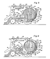
- the bale increases in diameter, as shown in Fig. 5, thereby expanding the course 26b of the apron 26 that extends between the guide members 40 and 48, and also expanding the course 52a of the apron 52 that extends between the guide members 54 and 62.
- the guide members 36 move rearwardly in the channels 80 to permit the expansion of the apron course 26b.
- the arm assemblies 90 and 98 pivot rearwardly about pivot 92 during expansion of apron course 26b and expansion of apron course 52a.
- the guide members 40 When the bale reaches the desired diameter, the guide members 40 are moved downwardly in the slots 74, as shown in Fig. 6, by further extending the hydraulic cylinders 72 to pivot the arms 68 downwardly on the shafts 70.
- the idler mechanisms 82 allow the guide members 34 to move forwardly in the channels 78 to relax some of the tension in the apron 26.
- the guide members 40 move to their lowermost position in slots 74 and the actuator mechanism 76 connected between the arms 68 and ramps 66 simultaneously causes the ramps 66 to pivot upwardly above the upper course 20a of the lower apron 20.
- the apron 26 and the ramps 66 close the rear of the front bale chamber 50 and thus cut off the delivery of material to the rear bale chamber 64.
- the core of another roll bale is then started in the front bale chamber 50.
- the completed bale which is still disposed in the rear bale chamber 64 is wrapped with twine or other suitable material in a conventional manner.
- the hydraulic cylinders 88 are extended to move the rear frame 22 upwardly to the open position of Fig. 8.
- the idler mechanisms 82 move the guide members 34 rearwardly in the channels 78 to help take up some of the slack in the apron 26.
- the control linkage 104 acts against the springs 94 to maintain the arm assembly 90 in a position where it does not interfere with the upward opening movement of the rear frame 22.
- the completed bale is discharged from the machine 10 in the manner indicated in Fig.
- the hydraulic cylinders 88 are contracted to move the rear frame 22 downwardly to its closed position, and the parts of the machine 10 are once again located as shown in Fig. 2 so that the baling operation may continue without interruption.
- the control linkage 104 as best shown in Figs. 9-11 includes link members 110 having a pivotal connection 112 at one of their ends with frame members 13 , which themselves pivotally are connected at 15 to the rear frame 22.
- the other ends of the link members 110 have elongated slots 114 formed therein which slidably receive pins 116 mounted on the lever portions 106 of the arm assembly 90.
- the hydraulic cylinders 88 which at one end are pivotally supported on the base unit 12, are pivotally coupled at their outer ends to the frame members 13 intermediate the opposite ends thereof, i.e. intermediate the pivots 15 and 112.
- the arm assembly 90 remains in the forward position shown in Fig. 9 and the pins 116 are disposed at the outer ends of the slots 114, thus preventing the springs 94 to pivot the arm assemblies 90 even further forward beyond the position shown in Figure 1.
- the arm assembly 90 is rotated rearwardly in a counterclockwise direction and opposite to the spring force of the springs 94 about pivot 92 as seen in Fig. 10 to a rearward position.
- This rotation of the arm assembly 90 causes the pins 116 to slide upwardly in the slots 114 toward the inner ends of the slots 114 without resulting in any movement of the link members 110, thereby constituting a lost-motion connection between the arm assembly 90 and the link members 110.
- the frame members 13 For raising the rear frame 22 as illustrated in Fig. 8 to discharge a completed bale from the rear chamber 64, the frame members 13 first are pivoted at 15 in a counterclockwise direction as viewed in Fig. 11 and until they abut against stops (not shown in the drawings) on the rear frame 22 by extension of the hydraulic cylinders 88 to an intermediate position. Thereafter, further extension of the hydraulic cylinders 88 effectively results in a pivoting of the rear frame 22 about the pivots 24 on the base frame 12.
- the pivoting of the frame members 13 causes upward movement of the link members 110 until the pins 116 reach the outer ends of the slots 114.
- the arm assembly 90 is then prevented from rotating forward about the pivot 92 from its rearwardmost position as shown in Figs. 6 and 7 and is held in this rearwardmost position by the control linkage 104, thereby preventing the arm assembly 90 from interfering with the upward opening movement of the rear frame 22 while discharging a bale from the rear bale chamber 64.
- the springs 94 would tend to urge the arm assembly 90 forwardly where it might interfere not only with the raising and lowering of the rear frame 22, but also with the discharge of a bale from the rear bale chamber 64.
- the arm assembly 90 is disposed in a generally upright orientation when the rear frame 22 is in its closed position and the second bale chamber 64 is empty.
- the arm assembly 90 further also is advantageously pivotally mounted on the rear frame generally at its lower end.
- the movements of the various parts of the roll baling machine 10 would be controlled automatically by using conventional electronic equipment. However, they may also be controlled mechanically by an operator with the aid of visual indicators.
- a roll baling machine of the type having an expandable bale forming chamber wherein completed bales may be discharged smoothly from the bale forming chamber without any machine component tending to interfere therewith as well as with the opening and the subsequent closing of the movable frame for effecting said discharge.
Landscapes
- Life Sciences & Earth Sciences (AREA)
- Environmental Sciences (AREA)
- Storage Of Harvested Produce (AREA)
Applications Claiming Priority (2)
| Application Number | Priority Date | Filing Date | Title |
|---|---|---|---|
| US556230 | 1983-11-29 | ||
| US06/556,230 US4517891A (en) | 1983-11-29 | 1983-11-29 | Control linkage for continuous roll baling machine |
Publications (2)
| Publication Number | Publication Date |
|---|---|
| EP0156041A1 true EP0156041A1 (fr) | 1985-10-02 |
| EP0156041B1 EP0156041B1 (fr) | 1989-02-01 |
Family
ID=24220445
Family Applications (1)
| Application Number | Title | Priority Date | Filing Date |
|---|---|---|---|
| EP84201718A Expired EP0156041B1 (fr) | 1983-11-29 | 1984-11-26 | Presse pour mise en balles cylindriques |
Country Status (5)
| Country | Link |
|---|---|
| US (1) | US4517891A (fr) |
| EP (1) | EP0156041B1 (fr) |
| AU (1) | AU563336B2 (fr) |
| CA (1) | CA1242351A (fr) |
| DE (1) | DE3476506D1 (fr) |
Cited By (5)
| Publication number | Priority date | Publication date | Assignee | Title |
|---|---|---|---|---|
| EP0189232A1 (fr) * | 1985-01-25 | 1986-07-30 | FORD NEW HOLLAND, INC. (a Delaware corp.) | Presse à balles cylindriques travaillant en continu |
| FR2591849A1 (fr) * | 1985-12-20 | 1987-06-26 | Inst Tech Agricole Lin | Presse enrouleuse a balles cylindriques a liage sans interruption du ramassage. |
| EP0254337A1 (fr) * | 1986-06-23 | 1988-01-27 | Beno Oldenhuis | Presse à balles rondes |
| DE3710550C1 (de) * | 1987-03-30 | 1988-06-30 | Zweegers & Zonen P J | Rollballenpresse fuer Erntegut |
| CN101965772A (zh) * | 2009-07-26 | 2011-02-09 | 卞康群 | 收割机秸秆收积装置 |
Families Citing this family (9)
| Publication number | Priority date | Publication date | Assignee | Title |
|---|---|---|---|---|
| DE3431389C2 (de) * | 1984-08-25 | 1994-03-17 | Claas Ohg | Verfahren zum Umschlingen eines Rundballens aus Erntegut |
| US4584827A (en) * | 1985-01-25 | 1986-04-29 | Sperry Corporation | Drive mechanism for roll baler |
| US7784400B2 (en) * | 2008-12-30 | 2010-08-31 | Cnh America Llc | Duckbill cam geometry for reduced actuation forces |
| NL1037435C2 (en) | 2009-11-02 | 2011-05-03 | Lely Patent Nv | Baling device to form bales of crop material. |
| WO2013014291A1 (fr) * | 2011-07-28 | 2013-01-31 | Varley Seamus | Machine de mise en balles rondes |
| US8733241B2 (en) | 2012-05-15 | 2014-05-27 | Cnh Industrial Canada, Ltd. | Continuous round baler chambers and conveyor system |
| US9402347B2 (en) | 2013-03-12 | 2016-08-02 | Cnh Industrial America Llc | Baler rear shield mechanism |
| US9918433B2 (en) | 2014-06-26 | 2018-03-20 | Cnh Industrial Canada, Ltd. | Continuous harvester and mobile wrapping systems and methods of using the same |
| US10986785B2 (en) * | 2018-06-26 | 2021-04-27 | Cnh Industrial America Llc | Continuous round baler and methods of using the same |
Citations (4)
| Publication number | Priority date | Publication date | Assignee | Title |
|---|---|---|---|---|
| US3901007A (en) * | 1973-04-24 | 1975-08-26 | Sperry Rand Corp | Hay roll forming machine |
| US4035999A (en) * | 1976-02-09 | 1977-07-19 | Crane Jack W | Crop material roll forming method and machine |
| DE2443838B2 (de) * | 1974-09-13 | 1978-11-02 | Gebrueder Welger, 3340 Wolfenbuettel | Aufsammei-Rollballenpresse |
| US4386493A (en) * | 1975-06-09 | 1983-06-07 | Hesston Corporation | Method and apparatus for making large round crop bales |
Family Cites Families (1)
| Publication number | Priority date | Publication date | Assignee | Title |
|---|---|---|---|---|
| US4208862A (en) * | 1979-03-29 | 1980-06-24 | Sperry Rand Corporation | Automatic bale ejection drive |
-
1983
- 1983-11-29 US US06/556,230 patent/US4517891A/en not_active Expired - Fee Related
-
1984
- 1984-10-30 CA CA000466585A patent/CA1242351A/fr not_active Expired
- 1984-11-26 EP EP84201718A patent/EP0156041B1/fr not_active Expired
- 1984-11-26 DE DE8484201718T patent/DE3476506D1/de not_active Expired
- 1984-11-28 AU AU35988/84A patent/AU563336B2/en not_active Ceased
Patent Citations (4)
| Publication number | Priority date | Publication date | Assignee | Title |
|---|---|---|---|---|
| US3901007A (en) * | 1973-04-24 | 1975-08-26 | Sperry Rand Corp | Hay roll forming machine |
| DE2443838B2 (de) * | 1974-09-13 | 1978-11-02 | Gebrueder Welger, 3340 Wolfenbuettel | Aufsammei-Rollballenpresse |
| US4386493A (en) * | 1975-06-09 | 1983-06-07 | Hesston Corporation | Method and apparatus for making large round crop bales |
| US4035999A (en) * | 1976-02-09 | 1977-07-19 | Crane Jack W | Crop material roll forming method and machine |
Cited By (7)
| Publication number | Priority date | Publication date | Assignee | Title |
|---|---|---|---|---|
| EP0189232A1 (fr) * | 1985-01-25 | 1986-07-30 | FORD NEW HOLLAND, INC. (a Delaware corp.) | Presse à balles cylindriques travaillant en continu |
| FR2591849A1 (fr) * | 1985-12-20 | 1987-06-26 | Inst Tech Agricole Lin | Presse enrouleuse a balles cylindriques a liage sans interruption du ramassage. |
| EP0254337A1 (fr) * | 1986-06-23 | 1988-01-27 | Beno Oldenhuis | Presse à balles rondes |
| DE3710550C1 (de) * | 1987-03-30 | 1988-06-30 | Zweegers & Zonen P J | Rollballenpresse fuer Erntegut |
| EP0284857A3 (en) * | 1987-03-30 | 1988-12-28 | P.J. Zweegers En Zonen Landbouwmachinefabriek B.V. | Rotobaler for crop |
| CN101965772A (zh) * | 2009-07-26 | 2011-02-09 | 卞康群 | 收割机秸秆收积装置 |
| CN101965772B (zh) * | 2009-07-26 | 2014-12-10 | 卞康群 | 收割机秸秆收积装置 |
Also Published As
| Publication number | Publication date |
|---|---|
| DE3476506D1 (en) | 1989-03-09 |
| EP0156041B1 (fr) | 1989-02-01 |
| US4517891A (en) | 1985-05-21 |
| CA1242351A (fr) | 1988-09-27 |
| AU563336B2 (en) | 1987-07-02 |
| AU3598884A (en) | 1985-06-13 |
Similar Documents
| Publication | Publication Date | Title |
|---|---|---|
| US4534285A (en) | Actuator mechanism for continuous roll baling machine | |
| CA1243541A (fr) | Ramasseuse-enrouleuse de fourrage en continu | |
| EP0156041A1 (fr) | Presse pour mise en balles cylindriques | |
| DE69905511T2 (de) | Rundballenerzeugungvorrichtung | |
| US4956968A (en) | Round baler with mechanism for dispensing wrapping material | |
| EP0252485B1 (fr) | Machine pour former des balles cylindriques de moissons | |
| EP0225398B1 (fr) | Presse-balles agricole | |
| US4667592A (en) | Agricultural baler | |
| US5581976A (en) | Method for wrapping round bales | |
| EP2777382B1 (fr) | Mécanisme de protection arrière de ramasseuse-presse | |
| US4470247A (en) | Round bale forming machine | |
| US20100162676A1 (en) | Duckbill cam geometry for reduced actuation forces | |
| EP0432830B1 (fr) | Appareil pour envelopper une balle dans une presse à balles rondes | |
| CA1045454A (fr) | Dispositif de derivation pour une ramasseuse-presse a balles cylindriques de produits de la moisson | |
| US5581974A (en) | Dual purpose cutting apparatus for round bale | |
| CA1044949A (fr) | Commande activee par balle pour le canal de cylindrage arriere d'une presse agricole a balles cylindriques | |
| CA1045453A (fr) | Controle du diametre d'une balle cylindrique de fourrage dans une ramasseuse-presse a balles cylindriques | |
| GB2090560A (en) | Agricultural baling machine | |
| US4150614A (en) | Automatic round bale wrapping assembly | |
| US4229934A (en) | Bale rolling machine | |
| GB1562975A (en) | Method of and machine for forming crop material rolls | |
| EP0766912B1 (fr) | Appareil et méthode pour envelopper des balles rondes | |
| US4559770A (en) | Round baler with dual function finger drum | |
| US5465658A (en) | Twine cutting apparatus for round baler | |
| US5327821A (en) | Round baler twine wrapper control mechanism |
Legal Events
| Date | Code | Title | Description |
|---|---|---|---|
| PUAI | Public reference made under article 153(3) epc to a published international application that has entered the european phase |
Free format text: ORIGINAL CODE: 0009012 |
|
| 17P | Request for examination filed |
Effective date: 19841126 |
|
| AK | Designated contracting states |
Designated state(s): DE FR GB |
|
| RAP1 | Party data changed (applicant data changed or rights of an application transferred) |
Owner name: NEW HOLLAND INC. |
|
| 17Q | First examination report despatched |
Effective date: 19870409 |
|
| RAP1 | Party data changed (applicant data changed or rights of an application transferred) |
Owner name: FORD NEW HOLLAND, INC. (A DELAWARE CORP.) |
|
| GRAA | (expected) grant |
Free format text: ORIGINAL CODE: 0009210 |
|
| AK | Designated contracting states |
Kind code of ref document: B1 Designated state(s): DE FR GB |
|
| REF | Corresponds to: |
Ref document number: 3476506 Country of ref document: DE Date of ref document: 19890309 |
|
| ET | Fr: translation filed | ||
| PLBE | No opposition filed within time limit |
Free format text: ORIGINAL CODE: 0009261 |
|
| STAA | Information on the status of an ep patent application or granted ep patent |
Free format text: STATUS: NO OPPOSITION FILED WITHIN TIME LIMIT |
|
| 26N | No opposition filed | ||
| PGFP | Annual fee paid to national office [announced via postgrant information from national office to epo] |
Ref country code: FR Payment date: 19921014 Year of fee payment: 9 |
|
| PGFP | Annual fee paid to national office [announced via postgrant information from national office to epo] |
Ref country code: DE Payment date: 19921016 Year of fee payment: 9 |
|
| PGFP | Annual fee paid to national office [announced via postgrant information from national office to epo] |
Ref country code: GB Payment date: 19921116 Year of fee payment: 9 |
|
| PG25 | Lapsed in a contracting state [announced via postgrant information from national office to epo] |
Ref country code: GB Effective date: 19931126 |
|
| GBPC | Gb: european patent ceased through non-payment of renewal fee |
Effective date: 19931126 |
|
| PG25 | Lapsed in a contracting state [announced via postgrant information from national office to epo] |
Ref country code: FR Effective date: 19940729 |
|
| PG25 | Lapsed in a contracting state [announced via postgrant information from national office to epo] |
Ref country code: DE Effective date: 19940802 |
|
| REG | Reference to a national code |
Ref country code: FR Ref legal event code: ST |