EP0156136A2 - Joint de haute pression - Google Patents
Joint de haute pression Download PDFInfo
- Publication number
- EP0156136A2 EP0156136A2 EP85101404A EP85101404A EP0156136A2 EP 0156136 A2 EP0156136 A2 EP 0156136A2 EP 85101404 A EP85101404 A EP 85101404A EP 85101404 A EP85101404 A EP 85101404A EP 0156136 A2 EP0156136 A2 EP 0156136A2
- Authority
- EP
- European Patent Office
- Prior art keywords
- ring
- annular
- support ring
- sealing
- circumferential surface
- Prior art date
- Legal status (The legal status is an assumption and is not a legal conclusion. Google has not performed a legal analysis and makes no representation as to the accuracy of the status listed.)
- Granted
Links
Images


Classifications
-
- F—MECHANICAL ENGINEERING; LIGHTING; HEATING; WEAPONS; BLASTING
- F16—ENGINEERING ELEMENTS AND UNITS; GENERAL MEASURES FOR PRODUCING AND MAINTAINING EFFECTIVE FUNCTIONING OF MACHINES OR INSTALLATIONS; THERMAL INSULATION IN GENERAL
- F16J—PISTONS; CYLINDERS; SEALINGS
- F16J15/00—Sealings
- F16J15/16—Sealings between relatively-moving surfaces
- F16J15/166—Sealings between relatively-moving surfaces with means to prevent the extrusion of the packing
-
- F—MECHANICAL ENGINEERING; LIGHTING; HEATING; WEAPONS; BLASTING
- F16—ENGINEERING ELEMENTS AND UNITS; GENERAL MEASURES FOR PRODUCING AND MAINTAINING EFFECTIVE FUNCTIONING OF MACHINES OR INSTALLATIONS; THERMAL INSULATION IN GENERAL
- F16J—PISTONS; CYLINDERS; SEALINGS
- F16J15/00—Sealings
- F16J15/56—Other sealings for reciprocating rods
-
- Y—GENERAL TAGGING OF NEW TECHNOLOGICAL DEVELOPMENTS; GENERAL TAGGING OF CROSS-SECTIONAL TECHNOLOGIES SPANNING OVER SEVERAL SECTIONS OF THE IPC; TECHNICAL SUBJECTS COVERED BY FORMER USPC CROSS-REFERENCE ART COLLECTIONS [XRACs] AND DIGESTS
- Y10—TECHNICAL SUBJECTS COVERED BY FORMER USPC
- Y10S—TECHNICAL SUBJECTS COVERED BY FORMER USPC CROSS-REFERENCE ART COLLECTIONS [XRACs] AND DIGESTS
- Y10S277/00—Seal for a joint or juncture
- Y10S277/909—Similar sealing structures for mounting on piston and about rod
Definitions
- the invention relates to a high-pressure seal for an axially displaceable and / or rotatable piston, a piston rod, shaft or the like, with at least one sealing or guide ring made of elastically or plastically deformable material under pressure and a support ring resting thereon.
- Known high-pressure seals of this type have a rigidly mounted support ring made of material which is practically non-deformable under operating conditions, which has a seal made of elastically or plastically deformable materials such as elastomers, PTFE-impregnated plastic or mineral fiber fabrics and / or compounds or the like in the form of a Grooved ring, bucket of Ururschette, a square cord, an Ab Streifringea or other supports and canuniert.
- a guide ring provided at the same time or instead of the seal made of the aforementioned deformable materials serves to support the seal and / or to guide plungers, piston rods, pistons or shafts and the like and must also be supported and chambered.
- the support ring is therefore provided rigidly mounted on the side of the seal facing away from the pressure.
- An annular gap remains between the parts moving relative to one another. If this is chosen so large that the parts run against each other and the resulting destruction of the sliding surfaces is avoided, the deformable seal or the guide ring is extruded into the annular gap under the operating pressure and, depending on the operating conditions, the seal is destroyed faster or slower. If, on the other hand, the annular gap is chosen to be so small that it is not possible to extrude the deformable seal or the guide ring into the annular gap, the inevitable radial path deviations lead to the tarnishing of the parts which are moved relative to one another and to one another and to the destruction of the sliding surfaces.
- the object of the invention is now to provide an uncomplicated high-pressure device of the type mentioned at the outset, which has an extended wear-free service life.
- the device of the type mentioned is equipped according to the invention with the features specified in the characterizing part of claim 1.
- Support ring is stored according to the invention in an annular groove of the sealing or guide ring and radially elastically displaceable under its limited deformation.
- the ring sp't between the support ring and the part moving opposite it can be chosen so small that extrusion of the dicliding or guide ring into the annular gap is excluded.
- the sliding surfaces of the support ring and piston, piston rod or shaft cannot be destroyed by lateral running, since the support ring is not rigidly mounted and can move radially.
- the support ring can be designed with a slight radial play relative to the ring web of the sealing or guide ring, so that misalignments caused by production and installation are compensated for between the support ring and piston, piston rod or shaft before the support ring is surrounded by the ring web of the sealing or guide ring under operating pressure .
- the invention further relates to a sealing or guide ring made of deformable material under pressure for a high-pressure seal according to claim 1 with the features mentioned in claim 5.
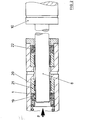
- the high-pressure seal for a plunger 6 shown in axial section in FIGS. 1, 1a and 1b comprises a guide ring 2 which, at its end cooperating with the support ring 1, has an annular groove 2a with an essentially radial annular step surface 2b, which is open towards this and towards the annular gap 3 to be sealed and has an axially projecting annular web 2c delimiting it on the side facing away from the annular gap 3.
- the guide ring 2 consists of filled PTFE.
- the support ring 1 made of sintered metal (DEVA metal) bears against the ring step surface 2b thereof. Its circumferential surface la facing the annular gap 3 is somewhat recessed relative to the circumferential surface 2d of the guide ring 2, which is more distant from the annular web 2c, in the case of a coaxial orientation.
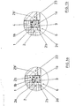
- the circumferential surface 2b 'of the ring web 2c facing the annular gap 3 corresponds in diameter to the circumferential surface 1b of the support ring 1 facing away from the annular gap 3 (FIG. 1a), but it can also be larger by a predetermined small distance before installation (hadial clearance 4 in FIG. 1b), but then rests against them in the operating state with elastic and / or plastic deformation.
- the support ring 1 is mounted so as to be radially elastically displaceable with limited deformation of the ring web 2c.
- the guide ring 2 has, in its axial end face facing away from the annular groove 2a, a groove which is essentially V-shaped in cross section for receiving a roof collar seal 7 au1.
- the high-pressure seal constructed in this way is received in a plunger bushing 5 and seals against the plunger 6 which can be displaced therein.
- a pressure ring 18 surrounding the plunger 6 is urged by a spring device 17 in the direction of the high-pressure seal and presses it against a radially inwardly projecting seat 23 of the plunger bushing 5, which protrudes radially so far in the direction of the plunger 6 that the side surface of the support ring 1 facing away from the pressure partially abuts against it.
- annular maintenance chamber 8 which is provided with a feed channel 12 and a discharge channel 13 in the form of radial bores for lubricating and / or cooling the plunger 6.
- a second high-pressure seal which comprises a maintenance 9 formed from roof seals, a guide ring 14 and a support ring 15 and is preloaded against the seat 23 by a holding element 16 which can be fixed in the plunger bushing 5.
- Guide ring 14 or support ring 15 correspond to the guide ring 2 or support ring 1 already described, both high-pressure seals point in the same direction.
- the plunger 6 is connected via a clutch 10 to the crosshead of a conventional crank drive (not shown) and is reciprocally displaceable in a delivery chamber 11 which is closed off by the high pressure seal. > During the delivery stroke (movement to the left in FIG. 1), the plunger 6 generates a delivery pressure in the delivery chamber 11, which is indicated by the arrow P. Under the effect of this pressure, the high-pressure seal pressed against the seat 23 by the spring device 17 and the pressure ring 1S is further compressed. The cross-sectionally V-shaped groove of the excessive guide ring 2 prevents excessive deformation of the roof boot seal 7.
- the guide ring 2 cannot be extruded even under high pressure through the very small annular gap 3 between the support ring 1 and the plunger 6 and presses the support ring 1 against the seat 23 of the plunger bushing 5. This pressing prevents the guide ring 2 from being extruded between the support ring 1 and the seat 23; by the resulting radially inward pressure of the guide ring 2 on the outer circumference of the support ring 1, it is at most minimally radially compressed.
- FIG. 2 A modified high-pressure seal for a plunger 6 is shown in FIG. 2, parts which correspond to FIGS. 1, 1a and 1b are not described and some are not identified in the figure.
- a support ring 1 which has already been described and is essentially the same, is mounted radially displaceably in a seal ring 19 in the manner also described above.
- the sealing ring 19 has on its axial end face facing away from the annular groove receiving the support ring 1, radial sealing lips which are one of the already known with respect to the plunger bushing wall or the plunger 6. unfold the appropriate sealing effect.
- the sealing ring 19 and the support ring 1 are not pressed directly against the seat of the plunger bushing, 21 but instead against a rigid retaining ring made of material which is not deformable under operating conditions and which has a large radial clearance with respect to the plunger piston that this cannot start on the retaining ring 21 .
- a guide ring 20 made of elastically and / or plastically deformable material is embedded in the inner circumferential surface of the retaining ring 21 for the contact of the plunger 6. Since a high-pressure seal of the sealing ring 19 and the support ring 1 is arranged on the front side of the guide ring 20, this does not have to be secured against deformation under pressure, as in the embodiment described with reference to FIG. 1 Arrangement in Fig. 1, a sealing ring 22 with radial sealing lips and a supporting ring supporting this provided by a bracket against one the retaining ring which is supported on the seat is prestressed with a guide ring embedded in its inner circumferential surface.
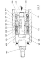
- FIG. 3 shows a piston 100 which is reciprocally displaceable in a cylinder 105 by a piston rod 106 and which is sealed against the inner wall of the cylinder 105 along which it slides by a high-pressure seal according to the invention.
- the high-pressure seal comprises a support ring 101 which is arranged in an annular groove 102a (cf. FIG. 3a) of a piston guide ring 102.
- the annular groove 102a is open toward the end of the piston guide ring 102 which cooperates with the support ring 101 and towards the annular gap 103 to be sealed and has an essentially radial annular step surface 102b and an axially projecting annular web 102c delimiting it on the side facing away from the annular gap 103.
- the circumferential surface 101a of the support ring 101 facing the annular gap p3 is somewhat recessed relative to the circumferential surface 102d of the guide ring 102 distant from the ring web 102c in the case of coaxial alignment.
- the circumferential surface 102b 'of the ring web 102c facing the annular gap 103 corresponds in diameter to the circumferential surface 101b of the support ring 101 facing away from the annular gap 103 or is a predetermined small distance, namely around the radial clearance 104, before it is installed.
- the materials used for the piston guide ring 102 and the support ring 101 correspond to the materials already specified in the aforementioned embodiments.
- the piston guide ring 102 In its axial end face facing away from the ring groove 102a, the piston guide ring 102 has a groove which is essentially V-shaped in cross section for receiving a roof boot seal 107.
- the piston 100 comprises two piston segments 108, 109 arranged on the end section of the piston rod 106, which are fixed to the piston rod 106 by a fastening element 113 and thereby fix an intermediate ring 112 between them in a clamped fit.
- the outer diameter of the piston segments 108, 109 and the intermediate ring 112 are dimensioned so much smaller than the inner diameter of the cylinder 105 that the piston ends are small. segments 108, 109 and the intermediate ring 112 even with small radii. Deflections of the piston in operation can not come into contact with the inner surface of the cylinder 105.
- a high-pressure seal is arranged between each piston segment 108 or 109 and the intermediate ring 112 such that the support ring 101 bears against the intermediate ring 112 and the high-pressure seals when the fastening element 113 is tightened by moving the piston segments 108, 109 towards one another from opposite sides against the intermediate ring 112 pressed and leicnt compressed and biased.
- the high-pressure seals point in opposite directions.
- the piston rod 106 is either coupled to a crosshead of a conventional crank drive via a coupling 110 or is used for axial power transmission.
- the reciprocating movement of the piston 100 and the corresponding change in volume of the cylinder chambers 111 or 123 generates a pressure P on the liquids located therein, for example to be conveyed; in the second case, a pressure is exerted on the piston 100, for example by introducing a hydraulic medium into the cylinder chambers 111 or 123, which pressure is transmitted to a device to be actuated by means of the piston rod 106.
- the piston guide ring 102 deforms and embeds the support ring 101 in a radially displaceable manner under the operating pressure in the cylinder chambers 111 and 123, which acts on the piston guide ring 102 and the support ring 101 via the roof boot seal 107.
- An extrusion of the piston guide ring 102 into the space between the inner wall of the cylinder 105 and the intermediate ring 112 is excluded because of the strong pressure of the support ring 101 against it and because of the only minimal annular gap 103.
- Manufacturing and installation-related misalignments between the inner wall of the cylinder 105 and the support ring 101 are compensated for by radial displacement of the support ring 101, which is particularly facilitated when, as in FIG. 3b, a radial clearance 104 between the ring web 102c of the piston guide ring 102 and the support ring 101 is provided.
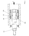
- Fig. 4 shows a modified high pressure seal of the already deformable type described with reference to Fig. 3, in which a deformable Ken guide ring 120 is embedded in the outer peripheral surface of the intermediate ring.
- sealing rings 119 and support rings 101 arranged in their annular groove are provided between the piston segments.
- the sealing rings 119 have radial sealing lips which fulfill the function of the roof boot seals 107 in FIG. 3. Since the operating pressure P does not occur in the space enclosed by the intermediate ring, the inner wall of the cylinder and the support rings 101, the piston guide ring 120 does not have to have any special support, but can simply be embedded in the outer circumferential surface of the intermediate ring.
- the function of the piston in Fig. 4 otherwise corresponds entirely to the d bens 100 in FIG. 3.
- the roof boot seal consisted of four PTFE-impregnated asbestos fabric sleeves, the plunger piston had a running surface with a chrome carbide layer MK22 applied by means of the melting process.
- a rigidly mounted support ring made of A B 4 S bronze was used, in which a band made of filled PTFE (compound no. 10 from Busalt & Luyken) was embedded as a guide ring.
- a support ring made of sintered metal with emergency running properties (DEVA metal) was used for the high-pressure seal according to the invention; the guide ring consisted, as in the known seal, of filled PTFE (compound No. 10 from Busak & Luyken).
- the running time to leakage was approximately 50 hours in the known high-pressure seal.
- the leak was due to the support ring worn by radially tarnished pistons and the collapsed roof seals.
- the high-pressure seal according to the invention still ran after 240 hours with flawless roof seals and undamaged guide ring; the experiment was stopped after this period.
- the support ring After 240 hours, the support ring showed slight traces of spotting evenly distributed over the entire inner circumferential surface, which are probably due to the fact that the support ring was radially compressed during the pressure stroke and calibrated by the harder plunger surface. These Assumption is supported by the fact that the inner diameter of the support ring has been increased by approximately 0.01 mm.
- the support ring made of metal with emergency running properties and a plunger with a much harder surface
Landscapes
- Engineering & Computer Science (AREA)
- General Engineering & Computer Science (AREA)
- Mechanical Engineering (AREA)
- Sealing Devices (AREA)
- Pistons, Piston Rings, And Cylinders (AREA)
- Details Of Reciprocating Pumps (AREA)
- Sealing With Elastic Sealing Lips (AREA)
Priority Applications (1)
| Application Number | Priority Date | Filing Date | Title |
|---|---|---|---|
| AT85101404T ATE42997T1 (de) | 1984-02-15 | 1985-02-09 | Hochdruckdichtung. |
Applications Claiming Priority (2)
| Application Number | Priority Date | Filing Date | Title |
|---|---|---|---|
| DE3405351 | 1984-02-15 | ||
| DE3405351A DE3405351C2 (de) | 1984-02-15 | 1984-02-15 | Hochdruckdichtung |
Publications (3)
| Publication Number | Publication Date |
|---|---|
| EP0156136A2 true EP0156136A2 (fr) | 1985-10-02 |
| EP0156136A3 EP0156136A3 (en) | 1986-08-06 |
| EP0156136B1 EP0156136B1 (fr) | 1989-05-10 |
Family
ID=6227774
Family Applications (1)
| Application Number | Title | Priority Date | Filing Date |
|---|---|---|---|
| EP85101404A Expired EP0156136B1 (fr) | 1984-02-15 | 1985-02-09 | Joint de haute pression |
Country Status (5)
| Country | Link |
|---|---|
| US (1) | US4602791A (fr) |
| EP (1) | EP0156136B1 (fr) |
| JP (1) | JPS60227062A (fr) |
| AT (1) | ATE42997T1 (fr) |
| DE (2) | DE3405351C2 (fr) |
Cited By (4)
| Publication number | Priority date | Publication date | Assignee | Title |
|---|---|---|---|---|
| EP0321280A3 (fr) * | 1987-12-18 | 1989-12-20 | Nok Corporation | Dispositif de joint |
| EP0362815A3 (fr) * | 1988-10-06 | 1992-12-02 | Stabilus GmbH | Dispositif à tige et récipient |
| WO2014095120A1 (fr) * | 2012-12-20 | 2014-06-26 | Robert Bosch Gmbh | Pompe à carburant alternative pour moteur à combustion interne |
| EP2881629A3 (fr) * | 2013-12-03 | 2015-07-15 | Carl Freudenberg KG | Joint d'étanchéité |
Families Citing this family (25)
| Publication number | Priority date | Publication date | Assignee | Title |
|---|---|---|---|---|
| GB8427913D0 (en) * | 1984-11-05 | 1984-12-12 | Dewandre Co Ltd C | Recuperation in hydraulic systems |
| DE3541466A1 (de) * | 1985-11-23 | 1987-05-27 | Reinhard Ulrich | Dichtungsanordnung fuer eine welle |
| JP2652376B2 (ja) * | 1987-04-17 | 1997-09-10 | 株式会社 丸山製作所 | 往復ポンプのシール機構 |
| US4886241A (en) * | 1987-09-16 | 1989-12-12 | Fisher Controls International, Inc. | Valve stem packing containment for high pressure, high temperature |
| DE3742676C1 (en) * | 1987-12-16 | 1989-06-22 | Merkel Martin Gmbh Co Kg | Method for sealing of a piston relative to a cylinder surface and high-pressure gasket for carrying out this method |
| JPH0739839Y2 (ja) * | 1989-07-31 | 1995-09-13 | 凸版印刷株式会社 | 無菌充填装置 |
| US5493951A (en) * | 1994-05-05 | 1996-02-27 | Harrison; Curtis W. | Lubrication and seal ring assembly for pump |
| US5992768A (en) * | 1997-12-08 | 1999-11-30 | Caterpillar Inc. | Fluid seal for cyclic high pressures within a fuel injector |
| US6236128B1 (en) | 1999-10-28 | 2001-05-22 | Siemens Westinghouse Power Corporation | Radial lead spanner nut assembly with integral seals for hydrogen-cooled power generators and associated methods |
| IL140828A (en) * | 2001-01-09 | 2008-08-07 | Vladimir Magaziner | High pressure sealing |
| US6558141B2 (en) | 2001-04-12 | 2003-05-06 | Ingersoll-Rand Company | Packing assembly and reciprocating plunger pump incorporating same |
| US20070273105A1 (en) * | 2004-03-11 | 2007-11-29 | Stanton Eddie N | Packing cartridges and pressure-dampening and voc-absorbing elements for plunger-type pumps |
| US8100407B2 (en) * | 2004-03-11 | 2012-01-24 | Stanton Eddie N | Packing cartridges and pressure-dampening elements for plunger-type pumps |
| US7322273B2 (en) * | 2004-08-13 | 2008-01-29 | The Stanley Works | Piston-piston rod retaining assembly for a hydraulic piston and cylinder unit |
| US7951226B2 (en) | 2005-03-11 | 2011-05-31 | Stanton Eddie N | Apparatuses and methods for reducing emissons of volatile organic compounds when pumping fluids containing volatile organic compounds with a positive displacement pump |
| US8679230B2 (en) | 2008-12-19 | 2014-03-25 | Michael L. Strickland | Reducing emissions of VOCs from low-pressure storage tanks |
| DE102014202794A1 (de) | 2014-02-17 | 2015-08-20 | Robert Bosch Gmbh | Kolben-Kraftstoffpumpe für eine Brennkraftmaschine |
| US10047623B2 (en) * | 2014-12-17 | 2018-08-14 | United Technologies Corporation | Compliant seal assembly and method of operating |
| CN108644524A (zh) * | 2018-05-24 | 2018-10-12 | 中国科学院力学研究所 | 一种耐高温高压空气的膨胀节补偿装置 |
| CN108662340B (zh) * | 2018-05-24 | 2020-10-09 | 中国科学院力学研究所 | 一种用于纯净空气风洞的密封膨胀节 |
| CN110375067B (zh) * | 2019-06-25 | 2024-06-14 | 北京北分瑞利分析仪器(集团)有限责任公司 | 一种应用于注射器的活塞密封结构 |
| EP4211359A2 (fr) | 2020-09-08 | 2023-07-19 | Dover Pumps & Process Solutions Segment, Inc. | Structures composites à gradient fonctionnel |
| WO2022056162A1 (fr) * | 2020-09-09 | 2022-03-17 | Waukesha Bearings Corporation | Structures composites pour des systèmes de compresseur de gaz à pistons |
| CN114989892B (zh) * | 2022-06-02 | 2023-09-15 | 安徽领先生物科技有限公司 | 一种精油高压密封萃取装置 |
| FR3138175B1 (fr) * | 2022-07-20 | 2024-10-11 | Safran Aircraft Engines | Procede de preparation d’un joint d’etancheite en polymere soumis a une pression en fatigue |
Family Cites Families (14)
| Publication number | Priority date | Publication date | Assignee | Title |
|---|---|---|---|---|
| US2509436A (en) * | 1947-07-12 | 1950-05-30 | Chicago Rawhide Mfg Co | Packing |
| GB692036A (en) * | 1950-03-03 | 1953-05-27 | John Lamb Murray Morrison | Improvements in or relating to sealing glands for pressure vessels |
| GB729306A (en) * | 1951-10-22 | 1955-05-04 | Steel Tite Piston Ring Company | Improvements in or relating to pistons and glands and wearing rings for use with thepiston rings and the gland rings |
| US3094337A (en) * | 1960-10-31 | 1963-06-18 | Universal Packing & Gasket Com | Seal ring |
| US3186702A (en) * | 1962-02-23 | 1965-06-01 | Tayco Dev | Liquid spring |
| GB1085280A (en) * | 1964-06-18 | 1967-09-27 | Dowty Rotol Ltd | High pressure packing gland |
| US3366392A (en) * | 1964-09-16 | 1968-01-30 | Budd Co | Piston seal |
| GB1198596A (en) * | 1968-04-29 | 1970-07-15 | Greene Tweed & Co Inc | Improvements in Sealing Devices |
| US3525530A (en) * | 1968-06-10 | 1970-08-25 | Gen Motors Corp | High pressure-low friction seal |
| DE1948432A1 (de) * | 1969-09-25 | 1971-05-19 | Merkel Asbest & Gummiwerke | Gummielastischer,gewebeverstaerkter Dichtring fuer einen ungeteilten Kolben |
| GB1395334A (en) * | 1971-12-31 | 1975-05-21 | Bal Ltd | Packing assemblies |
| DE2227042C3 (de) * | 1972-06-02 | 1980-09-18 | Integral Hydraulik & Co, 4000 Duesseldorf | Dichtungsanordnung |
| SU718655A1 (ru) * | 1978-07-20 | 1980-02-29 | Краснодарский компрессорный завод | Уплотнение дл поршней |
| DE3218427A1 (de) * | 1981-11-04 | 1983-05-11 | Johann 8882 Lauingen Lindner | Dichtung fuer einen hydraulikzylinder |
-
1984
- 1984-02-15 DE DE3405351A patent/DE3405351C2/de not_active Expired
-
1985
- 1985-02-09 AT AT85101404T patent/ATE42997T1/de active
- 1985-02-09 DE DE8585101404T patent/DE3570111D1/de not_active Expired
- 1985-02-09 EP EP85101404A patent/EP0156136B1/fr not_active Expired
- 1985-02-15 US US06/703,212 patent/US4602791A/en not_active Expired - Fee Related
- 1985-02-15 JP JP60029209A patent/JPS60227062A/ja active Pending
Cited By (8)
| Publication number | Priority date | Publication date | Assignee | Title |
|---|---|---|---|---|
| EP0321280A3 (fr) * | 1987-12-18 | 1989-12-20 | Nok Corporation | Dispositif de joint |
| EP0362815A3 (fr) * | 1988-10-06 | 1992-12-02 | Stabilus GmbH | Dispositif à tige et récipient |
| WO2014095120A1 (fr) * | 2012-12-20 | 2014-06-26 | Robert Bosch Gmbh | Pompe à carburant alternative pour moteur à combustion interne |
| WO2014095781A1 (fr) * | 2012-12-20 | 2014-06-26 | Robert Bosch Gmbh | Pompe à carburant à piston pour moteur à combustion interne |
| US20150369190A1 (en) * | 2012-12-20 | 2015-12-24 | Robert Bosch Gmbh | Piston fuel pump for an internal combustion engine |
| US10428814B2 (en) | 2012-12-20 | 2019-10-01 | Robert Bosch Gmbh | Piston fuel pump for an internal combustion engine |
| US10767644B2 (en) | 2012-12-20 | 2020-09-08 | Robert Bosch Gmbh | Piston fuel pump for an internal combustion engine |
| EP2881629A3 (fr) * | 2013-12-03 | 2015-07-15 | Carl Freudenberg KG | Joint d'étanchéité |
Also Published As
| Publication number | Publication date |
|---|---|
| DE3405351A1 (de) | 1985-08-29 |
| EP0156136A3 (en) | 1986-08-06 |
| DE3405351C2 (de) | 1986-06-12 |
| DE3570111D1 (en) | 1989-06-15 |
| ATE42997T1 (de) | 1989-05-15 |
| EP0156136B1 (fr) | 1989-05-10 |
| JPS60227062A (ja) | 1985-11-12 |
| US4602791A (en) | 1986-07-29 |
Similar Documents
| Publication | Publication Date | Title |
|---|---|---|
| EP0156136B1 (fr) | Joint de haute pression | |
| EP0646739B1 (fr) | Joint d'étanchéité pour tiges ou pistons | |
| DE69814111T2 (de) | Anordnung von kolbendichtungen für eine hochdruckpumpe | |
| EP0114590B1 (fr) | Garniture d'étanchéité pour appareils à haute pression | |
| DE2845920B1 (de) | Dichtung fuer hin- und hergehende Maschinenelemente | |
| DE3225906A1 (de) | Dichtung fuer hydraulische kolben oder kolbenstangen | |
| EP1356221B1 (fr) | Joint annulaire | |
| WO1998055783A1 (fr) | Element d'etancheite pour systemes de marche a sec et utilisation d'un element d'etancheite de ce type | |
| DE3244209C2 (de) | Dichtung zum Abdichten gegen hydraulische Medien, vorzugsweise Dichtabstreifelement | |
| DE2937459C3 (de) | Dichtungsanordnung für eine Kolbenpumpe | |
| DE3411824A1 (de) | Kolbeneinheit | |
| DE102010033647B4 (de) | Vorrichtung zum Abdichten einer Stange gegenüber einem Medium und Verfahren zum Abdichten einer Stange gegenüber einem Medium | |
| DE112014006785B4 (de) | Arbeitszylinder | |
| DE3414821C2 (de) | Dichtungsanordnung | |
| DE3782568T2 (de) | Dichtungsanordnung verwendbar bei hochdruckgas. | |
| DE19906733C2 (de) | Dichtungssystem für Kolben-Zylinder-Einheiten sowie Verfahren zum Instandsetzen eines derartigen Dichtungssystems | |
| DE2126827A1 (en) | Ptfe gasket ring - for fixed and/or moving machine parts in pressurized or evacuated zones | |
| EP4148303B1 (fr) | Agencement d'étanchéité doté d'un joint d'étanchéité entourant une tige mobile, dispositif de distribution permettant de distribuer un milieu fluide, ainsi que joint d'étanchéité entourant une tige mobile | |
| DE4129892C2 (de) | Axialkolbenmaschine mit mit Gleitringen versehenen Kolben | |
| DE2914695C2 (fr) | ||
| EP1288537B1 (fr) | Anneau d'étanchéité | |
| DE19802463B4 (de) | Dichtungsring | |
| DE1918690A1 (de) | Spaltabdichtung an kreiszylindrischen ungeschmierten Flaechen,insbesondere fuer trockenlaufende Kolben bzw. Kolbenstangen eines Kolbenverdichters | |
| EP1079157B1 (fr) | Garniture mécanique d'étanchéité | |
| DE2717297A1 (de) | Zylinder-kolbenanordnung fuer eine fluessigkeitspumpe |
Legal Events
| Date | Code | Title | Description |
|---|---|---|---|
| PUAI | Public reference made under article 153(3) epc to a published international application that has entered the european phase |
Free format text: ORIGINAL CODE: 0009012 |
|
| AK | Designated contracting states |
Designated state(s): AT BE CH DE FR GB IT LI LU NL SE |
|
| PUAL | Search report despatched |
Free format text: ORIGINAL CODE: 0009013 |
|
| AK | Designated contracting states |
Kind code of ref document: A3 Designated state(s): AT BE CH DE FR GB IT LI LU NL SE |
|
| 17P | Request for examination filed |
Effective date: 19870128 |
|
| 17Q | First examination report despatched |
Effective date: 19880114 |
|
| RAP1 | Party data changed (applicant data changed or rights of an application transferred) |
Owner name: BRAN + LUEBBE GMBH |
|
| ITF | It: translation for a ep patent filed | ||
| GRAA | (expected) grant |
Free format text: ORIGINAL CODE: 0009210 |
|
| AK | Designated contracting states |
Kind code of ref document: B1 Designated state(s): AT BE CH DE FR GB IT LI LU NL SE |
|
| PG25 | Lapsed in a contracting state [announced via postgrant information from national office to epo] |
Ref country code: NL Effective date: 19890510 Ref country code: GB Effective date: 19890510 |
|
| REF | Corresponds to: |
Ref document number: 42997 Country of ref document: AT Date of ref document: 19890515 Kind code of ref document: T |
|
| REF | Corresponds to: |
Ref document number: 3570111 Country of ref document: DE Date of ref document: 19890615 |
|
| ET | Fr: translation filed | ||
| NLV1 | Nl: lapsed or annulled due to failure to fulfill the requirements of art. 29p and 29m of the patents act | ||
| GBV | Gb: ep patent (uk) treated as always having been void in accordance with gb section 77(7)/1977 [no translation filed] | ||
| PG25 | Lapsed in a contracting state [announced via postgrant information from national office to epo] |
Ref country code: AT Effective date: 19900209 |
|
| PG25 | Lapsed in a contracting state [announced via postgrant information from national office to epo] |
Ref country code: SE Effective date: 19900210 |
|
| PG25 | Lapsed in a contracting state [announced via postgrant information from national office to epo] |
Ref country code: LU Free format text: LAPSE BECAUSE OF NON-PAYMENT OF DUE FEES Effective date: 19900228 Ref country code: LI Effective date: 19900228 Ref country code: CH Effective date: 19900228 Ref country code: BE Effective date: 19900228 |
|
| PLBE | No opposition filed within time limit |
Free format text: ORIGINAL CODE: 0009261 |
|
| STAA | Information on the status of an ep patent application or granted ep patent |
Free format text: STATUS: NO OPPOSITION FILED WITHIN TIME LIMIT |
|
| 26N | No opposition filed | ||
| BERE | Be: lapsed |
Owner name: BRAN + LUBBE G.M.B.H. Effective date: 19900228 |
|
| PG25 | Lapsed in a contracting state [announced via postgrant information from national office to epo] |
Ref country code: FR Effective date: 19901031 |
|
| REG | Reference to a national code |
Ref country code: CH Ref legal event code: PL |
|
| PG25 | Lapsed in a contracting state [announced via postgrant information from national office to epo] |
Ref country code: DE Effective date: 19901101 |
|
| REG | Reference to a national code |
Ref country code: FR Ref legal event code: ST |
|
| EUG | Se: european patent has lapsed |
Ref document number: 85101404.3 Effective date: 19901107 |