EP0156211A2 - Dispositif de pompage pour applications médicales - Google Patents
Dispositif de pompage pour applications médicales Download PDFInfo
- Publication number
- EP0156211A2 EP0156211A2 EP85102535A EP85102535A EP0156211A2 EP 0156211 A2 EP0156211 A2 EP 0156211A2 EP 85102535 A EP85102535 A EP 85102535A EP 85102535 A EP85102535 A EP 85102535A EP 0156211 A2 EP0156211 A2 EP 0156211A2
- Authority
- EP
- European Patent Office
- Prior art keywords
- pump
- arrangement according
- housing
- shut
- pressure
- Prior art date
- Legal status (The legal status is an assumption and is not a legal conclusion. Google has not performed a legal analysis and makes no representation as to the accuracy of the status listed.)
- Granted
Links
Images

Classifications
-
- F—MECHANICAL ENGINEERING; LIGHTING; HEATING; WEAPONS; BLASTING
- F04—POSITIVE - DISPLACEMENT MACHINES FOR LIQUIDS; PUMPS FOR LIQUIDS OR ELASTIC FLUIDS
- F04B—POSITIVE-DISPLACEMENT MACHINES FOR LIQUIDS; PUMPS
- F04B43/00—Machines, pumps, or pumping installations having flexible working members
- F04B43/02—Machines, pumps, or pumping installations having flexible working members having plate-like flexible members, e.g. diaphragms
- F04B43/06—Pumps having fluid drive
- F04B43/067—Pumps having fluid drive the fluid being actuated directly by a piston
-
- A—HUMAN NECESSITIES
- A61—MEDICAL OR VETERINARY SCIENCE; HYGIENE
- A61M—DEVICES FOR INTRODUCING MEDIA INTO, OR ONTO, THE BODY; DEVICES FOR TRANSDUCING BODY MEDIA OR FOR TAKING MEDIA FROM THE BODY; DEVICES FOR PRODUCING OR ENDING SLEEP OR STUPOR
- A61M60/00—Blood pumps; Devices for mechanical circulatory actuation; Balloon pumps for circulatory assistance
- A61M60/10—Location thereof with respect to the patient's body
- A61M60/104—Extracorporeal pumps, i.e. the blood being pumped outside the patient's body
-
- A—HUMAN NECESSITIES
- A61—MEDICAL OR VETERINARY SCIENCE; HYGIENE
- A61M—DEVICES FOR INTRODUCING MEDIA INTO, OR ONTO, THE BODY; DEVICES FOR TRANSDUCING BODY MEDIA OR FOR TAKING MEDIA FROM THE BODY; DEVICES FOR PRODUCING OR ENDING SLEEP OR STUPOR
- A61M60/00—Blood pumps; Devices for mechanical circulatory actuation; Balloon pumps for circulatory assistance
- A61M60/40—Details relating to driving
- A61M60/424—Details relating to driving for positive displacement blood pumps
- A61M60/427—Details relating to driving for positive displacement blood pumps the force acting on the blood contacting member being hydraulic or pneumatic
-
- A—HUMAN NECESSITIES
- A61—MEDICAL OR VETERINARY SCIENCE; HYGIENE
- A61M—DEVICES FOR INTRODUCING MEDIA INTO, OR ONTO, THE BODY; DEVICES FOR TRANSDUCING BODY MEDIA OR FOR TAKING MEDIA FROM THE BODY; DEVICES FOR PRODUCING OR ENDING SLEEP OR STUPOR
- A61M60/00—Blood pumps; Devices for mechanical circulatory actuation; Balloon pumps for circulatory assistance
- A61M60/50—Details relating to control
- A61M60/508—Electronic control means, e.g. for feedback regulation
- A61M60/538—Regulation using real-time blood pump operational parameter data, e.g. motor current
-
- A—HUMAN NECESSITIES
- A61—MEDICAL OR VETERINARY SCIENCE; HYGIENE
- A61M—DEVICES FOR INTRODUCING MEDIA INTO, OR ONTO, THE BODY; DEVICES FOR TRANSDUCING BODY MEDIA OR FOR TAKING MEDIA FROM THE BODY; DEVICES FOR PRODUCING OR ENDING SLEEP OR STUPOR
- A61M60/00—Blood pumps; Devices for mechanical circulatory actuation; Balloon pumps for circulatory assistance
- A61M60/80—Constructional details other than related to driving
- A61M60/835—Constructional details other than related to driving of positive displacement blood pumps
- A61M60/837—Aspects of flexible displacement members, e.g. shapes or materials
-
- A—HUMAN NECESSITIES
- A61—MEDICAL OR VETERINARY SCIENCE; HYGIENE
- A61M—DEVICES FOR INTRODUCING MEDIA INTO, OR ONTO, THE BODY; DEVICES FOR TRANSDUCING BODY MEDIA OR FOR TAKING MEDIA FROM THE BODY; DEVICES FOR PRODUCING OR ENDING SLEEP OR STUPOR
- A61M60/00—Blood pumps; Devices for mechanical circulatory actuation; Balloon pumps for circulatory assistance
- A61M60/80—Constructional details other than related to driving
- A61M60/845—Constructional details other than related to driving of extracorporeal blood pumps
- A61M60/851—Valves
- A61M60/853—Valves the valve being formed by a flexible tube element which is clamped for restricting the flow
-
- A—HUMAN NECESSITIES
- A61—MEDICAL OR VETERINARY SCIENCE; HYGIENE
- A61M—DEVICES FOR INTRODUCING MEDIA INTO, OR ONTO, THE BODY; DEVICES FOR TRANSDUCING BODY MEDIA OR FOR TAKING MEDIA FROM THE BODY; DEVICES FOR PRODUCING OR ENDING SLEEP OR STUPOR
- A61M60/00—Blood pumps; Devices for mechanical circulatory actuation; Balloon pumps for circulatory assistance
- A61M60/80—Constructional details other than related to driving
- A61M60/855—Constructional details other than related to driving of implantable pumps or pumping devices
- A61M60/89—Valves
- A61M60/892—Active valves, i.e. actuated by an external force
-
- Y—GENERAL TAGGING OF NEW TECHNOLOGICAL DEVELOPMENTS; GENERAL TAGGING OF CROSS-SECTIONAL TECHNOLOGIES SPANNING OVER SEVERAL SECTIONS OF THE IPC; TECHNICAL SUBJECTS COVERED BY FORMER USPC CROSS-REFERENCE ART COLLECTIONS [XRACs] AND DIGESTS
- Y10—TECHNICAL SUBJECTS COVERED BY FORMER USPC
- Y10S—TECHNICAL SUBJECTS COVERED BY FORMER USPC CROSS-REFERENCE ART COLLECTIONS [XRACs] AND DIGESTS
- Y10S128/00—Surgery
- Y10S128/12—Pressure infusion
Definitions
- the invention relates to a pump arrangement for medical purposes, in particular a blood or infusion pump, with at least one pump housing which has a space which is divided by an impermeable membrane in a working chamber and into a drive chamber, the working chamber having at least one opening for closing - And discharge of the fluid to be delivered is provided and the drive chamber can be acted upon with air as pump fluid and is connected to a pump having a limited pump volume, and with a valve connected to the drive chamber for pressure compensation when the pump changes stroke.
- a pump arrangement of the type mentioned is known from DE-OS 32 05 449. It essentially consists of a storage vessel that is divided into two chambers. One chamber can be filled and emptied with the fluid to be pumped, in particular blood, while the other chamber is alternately acted upon by air as the pump fluid. Between the two chambers, an elastically expandable, impermeable membrane is provided, which according to this DE-OS in Form of an elastic tube is formed. Both chambers are surrounded by a rigid, air-impermeable pump housing, which has an opening for the chamber containing the pump fluid, which opening is connected via a pipeline to the pump having a limited pump volume. This pump is designed as a bellows pump, which oscillates between the upper and lower dead center during pump operation.
- the chamber which can be acted upon by the pump fluid or the space which has the pump fluid is connected to the surroundings via vacuum and pressure relief valves.
- These valves have the task of maintaining a certain pressure value, namely a certain overpressure and underpressure when the pump is operating. If, for example, the pump is blocked or if the usual start-up difficulties occur, the pumping fluid is simply pumped in or out up to the pressure value controlled by the valves, which usually work automatically.
- the pump is operated in such a way that the pressure and vacuum valves are not actuated.
- the pump fluid is compressed when the pump chamber is emptied (excess pressure) and expanded when the pump chamber is filled (negative pressure).
- problems arise during operation of the pump arrangement, which above all affect the pump capacity of this arrangement.
- the pressure in the pump will fluctuate between a lower pressure value P min and an upper pressure value P max , the valves just not yet opening.
- V 1 going to 50 cm 3
- V 2 going to 0 cm 3
- the volume is thus expanded from 30 to 50 cm 3 .
- the invention is therefore based on the object of providing a pump arrangement of the type mentioned at the outset which completely fills and empties the pump chamber during operation within the set pressure limits.
- a control device which opens the valve before each stroke change of the pump and closes to ambient pressure after pressure equalization and then initiates the next stroke of the pump.
- the pump arrangement according to the invention has the advantage over the known pump arrangement that given given volumes of the pump housing and the pump (i.e. the inner volume of the pump housing and the bellows volume) the predetermined pressure limits are inevitably reached, that is to say the pump works completely satisfactorily.
- the entire pump arrangement can be built much smaller and is nevertheless completely satisfactory during operation.
- the pump arrangement according to the invention can advantageously be over- and / or under-pressure controlled, the known valves being used for this purpose.
- the entire system can be monitored and, if necessary, switched off by observing the entire pressure behavior, which is advantageously stored in a memory.
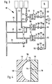
- FIG. 1 shows the pump arrangement according to the invention with 10.
- This pump arrangement 10 essentially consists of a pump housing 12 and a pump 14 having a limited pump volume, in particular a piston pump or a bellows pump. The latter is shown in Fig. 1.
- the pump housing has two chambers, namely one.
- Working chamber 16 for the liquid to be pumped and a drive chamber 18 for the fluid to be pumped in and out by the pump 16, in particular air.
- the working chamber 16 has at least one / opening, two openings 20 and 22 being shown in FIG. 1, through which the liquid to be pumped can be pumped into and pumped out of the first pumping chamber.
- the two openings 20 and 22 are each connected to hose lines 24 and 26, which are further connected to storage vessels or downstream devices (not shown) which are acted upon by the liquid to be pumped.
- hose lines 24 and 26 can be blocked with shut-off devices 28 and 30, preferably electromagnetic hose clamps, which are actuated in push-pull. If it is assumed that the line 24 is to serve as a liquid supply line and the line 26 is to serve as a liquid discharge line, the shut-off device 28 is open in the filling phase, while the shut-off device 30 is locked. In the emptying phase, the switch is made accordingly, that is to say the terminal 30 is opened and the terminal 28 is closed.
- the drive chamber 18 is also open to the outside with an / opening 32 which, like the other openings 20 and 22, passes through the pump housing, so that through this opening 32 a pumping fluid can be pumped in and out.
- This opening 32 is followed by an essentially rigid line 34, which advantageously has a flange 36 at its end.
- This flange 36 advantageously spanned a hydrophobic membrane 38, the pores of which are dimensioned such that no germs can enter the line 34 and thus the drive chamber 18.
- the membrane 38 serves as a safety device for a break in the pump membrane 40.
- This pump membrane 40 divides the two pumping chambers 16 and 18 and can advantageously have a preformed curved shape. In this embodiment, it can rest against the walls of the chambers without expansion.
- the pump diaphragm 40 has a flat design and can advantageously be arranged in the pump housing 12 already preloaded by a certain amount. In this case, the membrane expands elastically during pumping operation and tends to return to the initial state when there is relief, for example when the pump 14 is vented or the terminals 28 and 30 are opened.
- the pump housing 12 consists of two housing halves 41 and 42, between which the membrane is first inserted during manufacture and which are then glued or welded together.
- An easily moldable plastic material for example PVC, polyacrylic glass or polycarbonate, is usually chosen as the material for the pump housing, while soft PVC, polyethylene or the like, as long as the material for the pump membrane Membrane is inelastic, or rubber-elastic materials such as silicone rubber and the like can be used.
- the pump volume V 1 is determined by the volumes of the two
- Chambers 16 and 18 determined. Different standard volumes will advantageously be used, depending on which pumping rates are to be generated.
- the pump housing 12 including the hoses 24 and 26 connected to it and the line 34, is used as a so-called disposable part, which leaves the production site in a sterile state.
- the contour of the chambers 16 and 18 is identical, as is shown in FIG. 1.
- the contours of the chambers 16 and 18 can be asymmetrical.
- Example 2 in which an elastic pump membrane is advantageously used as the pump membrane 40.
- the flat membrane lies directly on the chamber wall, so that practically a second pumping chamber is dispensed with and the second pumping chamber - as explained above - is in turn connected to the pump 14. If a sufficiently elastic membrane is selected, such a pump is referred to as self-draining.
- the contour of the chambers 16 and 18 can also be designed such that the pump arrangement 10 is regarded as self-priming.
- a design is shown in Fig. 3 in the middle pump arrangement.
- the membrane is on the side of the pump 14 on the flat wall, so that the drive chamber 18 is omitted in the unloaded state.
- an elastic, possibly preloaded pump membrane 40 is also used.
- the pump arrangement 10 can have a variable internal volume V 1 .
- this variable is typed into a control unit in connection with the volume to be pumped, or the pump housing 12 has, depending on the volume V 1, special identification marks in the form of projections 43 on the outer wall, which are inserted when the pump housing 12 is inserted trigger a certain contact in a control device, not shown, which leads to the storage of the pump volume V 1 in the control device. This is particularly the case with so-called cassettes which are inserted into such a control device.
- the pump 14, as shown in Fig. 1, is designed as a bellows pump and consequently consists of a housing 44 in which a bellows 46 is arranged, which is pressed together or pressed apart by means of a reciprocating plunger 48.
- the end of this bellows 46 is to be connected to the pump housing 12, in particular to the line 34, via a rigid line 50, the end of which has a flange 52, the two flanges 36 and 52 being fastened to one another.
- the line 50 is advantageously closed in the uncoupled state, so that no air can escape as a result. This is of particular interest if the pump 14 is connected to a plurality of pump housings 12 via a line system, as shown in FIG. 3. In such a case, line 50 is advantageously automatically closed; if there is no connection to a pump housing 12, but is open, which is advantageously achieved by an automatically acting valve arrangement, as explained below, when the connection is established.
- a particularly preferred embodiment of the invention is that the ventilation of the pump arrangement 10 is carried out at the top and bottom dead center of the pump 14.
- the housing 44 of the pump 14 is equipped with contacts 58 and 60 which cooperate with a contact 62 which is arranged on the bellows 46. These contacts are connected via lines 64, 66, 68 to a control device 70, which in turn is connected to the valve 56 via a line 72.
- control device is connected to the shut-off device 28 and 30 via a line 74 and a line 76.
- the control device 70 switches terminals 28 and 30, i.e. to fill the chamber 16, the clamp 28 is opened and the clamp 30 is closed, while to empty the chamber 16 the clamp 28 is closed and the clamp 30 is opened.
- the pump arrangement 10 in particular the drive chamber 18 and the interior of the bellows 46, is advantageously opened at each of these dead points by opening the valve 56, which likewise causes the control unit 70 to open by closing the contacts 56-60 until the pump assembly 10 is pressure balanced.
- the two terminals 28 and 30 closed.
- the pump arrangement is advantageously operated with certain limit pressures both in the underpressure range and in the overpressure range. If these limit values are exceeded, the pressure limiting valves 78 and 80 open, which maintain a certain fixed pressure limit value during the pumping phase of the pump 14. These pressure relief valves 78 and 80 are automatically closed when the pump has reached its top or bottom dead center. For the rest, such a pressure limitation arrangement is described in DE-OS 32 05 449, the disclosure of which is expressly incorporated by reference.
- the underpressure or overpressure to be achieved essentially depends on the ratio of the pump volume V 1 and the volume V 2 of the extended bellows 46.
- the pressure limit value of the pressure limiting valves 78 and 80 which is advantageously at least 10% above the respective pressure limit values which are determined on the basis of the selected arrangement.
- limit pressure values are chosen so that the materials used can easily withstand these pressures. In this respect, they are in a range of 100 mbar - 3 bar, preferably 400 mbar - 2 bar.
- the control unit 70 first switches on the terminal 28, opens the valve 56 to set the pressure to the normal pressure value and then opens the terminal 30.
- the phase position of the pump 14 is switched, which then switches to the compression phase, i.e. is transferred into the drain phase. This causes the pump diaphragm to move to the left as a result of the resulting excess pressure until it has come to rest on the wall of the left-hand chamber half 16, i.e. until the state of complete emptying is reached.
- the other overpressure limiting valve 80 opens and keeps this overpressure constant.
- valve 56 is actuated again to set the atmospheric pressure value.
- the filling phase then begins again.
- a special infusion device is shown at 82 in FIG. 2, the same reference numerals as in FIG. 1 being shown for the same parts.
- This infusion device 82 has an infusion bag 84 which is connected to the pump housing 85 via the line 24, but which has only one opening 20, which also serves as a supply and discharge opening. Such an embodiment with only one opening is one of the preferred embodiments.
- the line 24 branches at the branching point 86, from which the line 88, which is connected to the opening 20, and the line 26 branches off.
- Pump assembly 85 has the pump housing a drive chamber 18 which corresponds to A shown in Fig. 1 ntriebshunt 18mony.Eb aboard the pump housing a drive chamber 18 which corresponds to A shown in Fig. 1 ntriebshunt 18mother.Eb aboard the pump housing a drive chamber 18 which corresponds to A shown in Fig. 1 ntriebshunt 18mony.Eb aboard the pump diaphragm 40 of the pump diaphragm shown in Fig. 1 40. However, completely lacking the working chamber 16 acc. Fig. L. As a result, the flat membrane 40 lies completely against the wall of the housing half 41.
- the bellows pump 14 can support the filling process, the valve 56 being actuated in accordance with the mode of operation described in FIG. is only opened at the upper and lower dead points.
- the valve 56 can also be operated during the filling phase, i.e. Expansion of the bellows 46, be opened, which leads to an automatic filling process due to the pressure of the water column. This embodiment is particularly preferred in the case of the infusion device 82 shown in FIG. 2.
- the bellows 46 is then compressed with the valve 56 closed and vented at the bottom dead center.
- the automatic filling phase then begins again.
- the symmetrical pump housing according to FIG. 1 can be used, provided the membrane has the same elastic properties.
- the restoring force can be here of the membrane lead to the introduction of air bubbles into the working chamber 16, so that air sensors 90 are advantageously attached to the line 28, which are connected via line 91 to the control device 70 and can switch off the entire device.
- FIG. 3 shows a pump device 92 which has four connections for four pump housings each, of which only three are occupied.
- line 50 From the pump 14, line 50 in turn goes off, into which valve 56 is switched on via line 54.
- line 50 has four branches 96, from which lines 98 depart, the ends of which each have connections 100.
- These connections 100 are advantageously equipped with a shut-off valve 102, which is opened when the line 34 is connected.
- the pump device 92 has two pump housings 12, as shown in FIG. 1, and an asymmetrical pump housing 104, which will be explained below.
- Pump devices 92 of this type are used particularly advantageously in intensive care medicine, in which the patient is provided with a plurality of infusion lines.
- pump housings 12, 104 with the same internal volume V 1 are advantageously used, the pump being operated at the corresponding rate at the desired rate.
- the pump size V 1 advantageously increases either by the factors 2, 4, 8 etc. or by the factors 4, 16, 32 etc.
- the volumes V 1 and V 2 should be designed such that generally one continuous pumping rate achieved without long break times can be.
- the clamp 30 can remain closed, pumping back into the bag when the clamp 28 is open or only increasing the vacuum in the pump housing 12 when the clamp 28 is also closed.
- shut-off devices 28 and 30 or 106 The usual magnetic or mechanical clamps can be used as shut-off devices 28 and 30 or 106, with combined clamps being preferred for both shut-off devices 28 and 30.
- Combinations clamps of this type in which only one of the clamps is always open while the other is inevitably closed, are shown at 108 in FIG. 3. This terminal 108 acc. Fig. 3 is moved linearly between the two contact points.
- a cam is also conceivable, which is attached to a disk and which is transferred from the one closed position to the other closed position by a certain amount.
- valves can therefore be positively guided or can also be controlled if electromagnetic valves are used.
- the asymmetrical pump housing 104 according to FIG. 4 is enlarged. 3 shown.
- This pump housing 104 has a second chamber half 110 and a / chamber half 112, the chamber half 110 being designed in the form of a flat plate, while the chamber half 112 has a hemispherical cavity 114. Both chamber halves are separated from the pump membrane 116. In addition, both chamber halves 110 and 112 have openings 118 and 120.
- opening 118 is connected to line 34, while opening 120 is connected to line 88.
- this form of pump is self-resetting when the membrane 116 lies completely against the inner wall of the pump housing 112 has and the pump 14 is compressed.
- valve 56 is advantageously opened at the bottom dead center, with the result that the membrane 116 returns to the starting position.
- the space 114 automatically fills with the pump liquid. It is therefore a self-priming pump.
- the membrane 116 is carried along as the pump expands to the rear until it attaches has created the inner wall of the cavity 114.
- the system is then vented by opening the valve 56, with the result that the membrane 116 returns to its original position due to its elastic restoring force and presses the stored liquid through the opening 118. It is therefore a self-pumping pump.
- the pump arrangements according to the invention can advantageously be connected to a microprocessor-controlled evaluation and / or control unit.
- the ratios of the quantities to be conveyed and the actual quantities can be programmable here.
- these markings 43 can already be used to program these units to the specific pump housing types, regardless of whether symmetrical or asymmetrical pump housings are used.
Landscapes
- Health & Medical Sciences (AREA)
- Engineering & Computer Science (AREA)
- Heart & Thoracic Surgery (AREA)
- Mechanical Engineering (AREA)
- Life Sciences & Earth Sciences (AREA)
- Anesthesiology (AREA)
- Biomedical Technology (AREA)
- Hematology (AREA)
- Cardiology (AREA)
- Animal Behavior & Ethology (AREA)
- General Health & Medical Sciences (AREA)
- Public Health (AREA)
- Veterinary Medicine (AREA)
- General Engineering & Computer Science (AREA)
- Reciprocating Pumps (AREA)
- Infusion, Injection, And Reservoir Apparatuses (AREA)
- External Artificial Organs (AREA)
Applications Claiming Priority (2)
| Application Number | Priority Date | Filing Date | Title |
|---|---|---|---|
| DE3408331A DE3408331C2 (de) | 1984-03-07 | 1984-03-07 | Pumpanordnung für medizinische Zwecke |
| DE3408331 | 1985-04-15 |
Publications (3)
| Publication Number | Publication Date |
|---|---|
| EP0156211A2 true EP0156211A2 (fr) | 1985-10-02 |
| EP0156211A3 EP0156211A3 (en) | 1987-10-07 |
| EP0156211B1 EP0156211B1 (fr) | 1991-05-22 |
Family
ID=6229805
Family Applications (1)
| Application Number | Title | Priority Date | Filing Date |
|---|---|---|---|
| EP85102535A Expired - Lifetime EP0156211B1 (fr) | 1984-03-07 | 1985-03-06 | Dispositif de pompage pour applications médicales |
Country Status (4)
| Country | Link |
|---|---|
| US (1) | US4634430A (fr) |
| EP (1) | EP0156211B1 (fr) |
| JP (1) | JPH0778389B2 (fr) |
| DE (2) | DE3408331C2 (fr) |
Cited By (9)
| Publication number | Priority date | Publication date | Assignee | Title |
|---|---|---|---|---|
| WO1987005225A3 (fr) * | 1986-03-04 | 1987-11-19 | Dean L Kamen | Systeme de regulation d'un fluide de mesure de pression |
| US4976162A (en) * | 1987-09-03 | 1990-12-11 | Kamen Dean L | Enhanced pressure measurement flow control system |
| EP0659444A1 (fr) * | 1993-12-20 | 1995-06-28 | Stöckert Instrumente GmbH | Appareil de pompage de sang |
| WO2007088530A1 (fr) * | 2006-02-01 | 2007-08-09 | Carmeli Adahan | Système d'aspiration, procédé et trousse |
| EP2216057A2 (fr) | 2007-05-07 | 2010-08-11 | Carmeli Adahan | Système de suction |
| US8506554B2 (en) | 2005-07-24 | 2013-08-13 | Carmeli Adahan | Wound closure and drainage system |
| WO2018114727A1 (fr) * | 2016-12-20 | 2018-06-28 | Fresenius Medical Care Deutschland Gmbh | Pompe volumétrique pour liquides médicaux et dispositif de traitement du sang ainsi que procédé de commande associé |
| WO2024213543A1 (fr) * | 2023-04-12 | 2024-10-17 | Cytiva Sweden Ab | Pompe actionnée par liquide, unité de pompe, et procédé de pompage d'un fluide de traitement |
| US12674448B2 (en) | 2022-04-22 | 2026-07-07 | Cytiva Sweden Ab | Pump for a bioprocessing system |
Families Citing this family (135)
| Publication number | Priority date | Publication date | Assignee | Title |
|---|---|---|---|---|
| DE3605664A1 (de) * | 1986-02-21 | 1987-08-27 | Siemens Ag | Folienspeicher fuer ein medikamentendosiergeraet |
| US5088515A (en) * | 1989-05-01 | 1992-02-18 | Kamen Dean L | Valve system with removable fluid interface |
| US4826482A (en) * | 1986-03-04 | 1989-05-02 | Kamen Dean L | Enhanced pressure measurement flow control system |
| US6406276B1 (en) * | 1986-03-04 | 2002-06-18 | Deka Products Limited Partnership | Constant-pressure fluid supply system with multiple fluid capability |
| US4836756A (en) * | 1986-08-28 | 1989-06-06 | Nippon Pillar Packing Co., Ltd. | Pneumatic pumping device |
| US4808167A (en) * | 1987-01-16 | 1989-02-28 | Pacesetter Infusion, Ltd. | Medication infusion system with disposable pump/battery cassette |
| US4850972A (en) * | 1987-01-16 | 1989-07-25 | Pacesetter Infusion, Ltd. | Progammable multiple pump medication infusion system with printer |
| NL8700389A (nl) * | 1987-02-17 | 1988-09-16 | Physio B V | Inrichting voor het beademen van patienten. |
| US5066282A (en) * | 1987-09-23 | 1991-11-19 | Leocor, Inc. | Positive displacement piston driven blood pump |
| US5019244A (en) * | 1987-11-16 | 1991-05-28 | Cole Jr Howard W | Method of separating mineral particles by froth flotation |
| US4830737A (en) * | 1987-11-16 | 1989-05-16 | Cole Jr Howard W | Apparatus and method for controlling the flow of foam at low flow rates |
| US5000739A (en) * | 1988-07-12 | 1991-03-19 | Pinewood Medical, Inc. | Programmable infusion pump |
| JPH02131770A (ja) * | 1988-09-14 | 1990-05-21 | Hitoshi Koyanagi | 医療用ポンプの駆動装置 |
| US4929234A (en) * | 1989-03-30 | 1990-05-29 | Tien Chen A | Automatic drip infusion set |
| US5322506A (en) * | 1989-07-31 | 1994-06-21 | C. R. Bard, Inc. | Irrigation system with high flow bypass for use with endoscopic procedure |
| CA1337714C (fr) * | 1989-07-31 | 1995-12-12 | Karen E. Kullas | Systeme d'irrigation a utiliser avec une methode endoscopique |
| US5242384A (en) * | 1989-11-13 | 1993-09-07 | Davol, Inc. | Blood pumping and processing system |
| DE9005547U1 (de) * | 1990-05-16 | 1990-07-19 | Grießer, Heinz, 8900 Augsburg | Doppelt wirkende Membranpumpe |
| DK8391A (da) * | 1991-01-18 | 1992-07-19 | Uno Plast As | Sugepumpe til brug ved udsugning af legemsvaeske fra kropshulrum |
| US5219331A (en) * | 1991-05-07 | 1993-06-15 | Imed Corporation | Pumping system for intravenous administration of a secondary treatment fluid |
| GB2261709A (en) * | 1991-05-31 | 1993-05-26 | Derek Frank Ernest Hodgson | Pumps |
| US5207666A (en) * | 1991-08-30 | 1993-05-04 | Infusaid, Inc. | Passive shuttle metering device for implantable drug delivery system |
| US5171301A (en) * | 1991-10-15 | 1992-12-15 | Imed Corporation | Multiple mini-pump infusion system |
| US5755683A (en) * | 1995-06-07 | 1998-05-26 | Deka Products Limited Partnership | Stopcock valve |
| US5713865A (en) * | 1991-11-15 | 1998-02-03 | Deka Products Limited Partnership | Intravenous-line air-elimination system |
| US5193986A (en) * | 1992-01-06 | 1993-03-16 | Grant Manufacturing Corporation | Fluid pump |
| US5423738A (en) * | 1992-03-13 | 1995-06-13 | Robinson; Thomas C. | Blood pumping and processing system |
| US5267964A (en) * | 1992-03-23 | 1993-12-07 | Clintec Nutrition Co. | Fluid control device including automatic valve |
| US5342313A (en) * | 1992-11-02 | 1994-08-30 | Infusion Technologies Corporation | Fluid pump for a flexible, variable geometry reservoir |
| US5232439A (en) * | 1992-11-02 | 1993-08-03 | Infusion Technologies Corporation | Method for pumping fluid from a flexible, variable geometry reservoir |
| US5474683A (en) * | 1993-03-03 | 1995-12-12 | Deka Products Limited Partnership | Peritoneal dialysis systems and methods employing pneumatic pressure and temperature-corrected liquid volume measurements |
| ATE204770T1 (de) * | 1993-03-03 | 2001-09-15 | Deka Products Lp | Kassette für periotonealdialyse |
| US5350357A (en) * | 1993-03-03 | 1994-09-27 | Deka Products Limited Partnership | Peritoneal dialysis systems employing a liquid distribution and pumping cassette that emulates gravity flow |
| US5438510A (en) * | 1993-03-03 | 1995-08-01 | Deka Products Limited Partnership | User interface and monitoring functions for automated peritoneal dialysis systems |
| US5324422A (en) * | 1993-03-03 | 1994-06-28 | Baxter International Inc. | User interface for automated peritoneal dialysis systems |
| US5431626A (en) * | 1993-03-03 | 1995-07-11 | Deka Products Limited Partnership | Liquid pumping mechanisms for peritoneal dialysis systems employing fluid pressure |
| US5398850A (en) * | 1993-08-06 | 1995-03-21 | River Medical, Inc. | Gas delivery apparatus for infusion |
| US5398851A (en) * | 1993-08-06 | 1995-03-21 | River Medical, Inc. | Liquid delivery device |
| US5492535A (en) * | 1994-04-06 | 1996-02-20 | Cordis Corporation | Hand-powered pumping apparatus for perfusion and other fluid catheterization procedures |
| US5529463A (en) * | 1994-04-19 | 1996-06-25 | Cordis Corporation | Pumping apparatus for perfusion and other fluid catheterization procedures |
| IL115327A (en) * | 1994-10-07 | 2000-08-13 | Bayer Ag | Diaphragm pump |
| US5645540A (en) * | 1994-10-11 | 1997-07-08 | Stryker Corporation | Blood conservation system |
| US5554011A (en) * | 1994-10-27 | 1996-09-10 | Symbiosis Corporation | Medical fluid pump powered by a constant source of vacuum |
| US6699213B1 (en) | 1995-08-03 | 2004-03-02 | Medela Holding Ag | Diaphragm pump protection device for a breastpump |
| US5938634A (en) * | 1995-09-08 | 1999-08-17 | Baxter International Inc. | Peritoneal dialysis system with variable pressure drive |
| DE19533595C2 (de) * | 1995-09-11 | 1999-10-14 | Deco Delta Gmbh | Extrakorporale Blutpumpe |
| US6123519A (en) * | 1995-10-03 | 2000-09-26 | Terumo Kabushiki Kaisha | Delivery blood storing member-equipped blood reservoir tank and blood delivery instrument for extracorporeal circulation circuit |
| US5792108A (en) * | 1995-10-23 | 1998-08-11 | C. R. Bard, Inc. | Self-priming pulsed lavage pump |
| US5941847A (en) * | 1998-02-06 | 1999-08-24 | Medela Holding Ag | Breast shield with vacuum isolation element |
| US6041801A (en) * | 1998-07-01 | 2000-03-28 | Deka Products Limited Partnership | System and method for measuring when fluid has stopped flowing within a line |
| US6394417B1 (en) * | 1998-10-09 | 2002-05-28 | Swagelok Co. | Sanitary diaphragm valve |
| US6604908B1 (en) * | 1999-07-20 | 2003-08-12 | Deka Products Limited Partnership | Methods and systems for pulsed delivery of fluids from a pump |
| US6416293B1 (en) * | 1999-07-20 | 2002-07-09 | Deka Products Limited Partnership | Pumping cartridge including a bypass valve and method for directing flow in a pumping cartridge |
| US6877713B1 (en) | 1999-07-20 | 2005-04-12 | Deka Products Limited Partnership | Tube occluder and method for occluding collapsible tubes |
| US6497676B1 (en) * | 2000-02-10 | 2002-12-24 | Baxter International | Method and apparatus for monitoring and controlling peritoneal dialysis therapy |
| ES2174737B1 (es) * | 2000-12-05 | 2003-10-16 | Lucas Victor Grifols | Bomba de membrana para liquidos. |
| US6905314B2 (en) | 2001-10-16 | 2005-06-14 | Baxter International Inc. | Pump having flexible liner and compounding apparatus having such a pump |
| US20030017066A1 (en) * | 2001-07-19 | 2003-01-23 | Baxter International Inc. | Apparatus, flexible bag and method for dispensing |
| US6769231B2 (en) | 2001-07-19 | 2004-08-03 | Baxter International, Inc. | Apparatus, method and flexible bag for use in manufacturing |
| US20030017056A1 (en) * | 2001-07-19 | 2003-01-23 | Baxter International Inc. | Pump having flexible liner and merchandiser having such a pump |
| US6749582B2 (en) | 2002-04-30 | 2004-06-15 | The First Years Inc. | Pumping breast milk |
| DE20207740U1 (de) | 2002-05-15 | 2002-08-22 | Heimomed Heinze GmbH & Co. KG, 50170 Kerpen | Vorrichtung zur Vakuumerzeugung |
| US7087036B2 (en) * | 2002-05-24 | 2006-08-08 | Baxter International Inc. | Fail safe system for operating medical fluid valves |
| US7153286B2 (en) | 2002-05-24 | 2006-12-26 | Baxter International Inc. | Automated dialysis system |
| US20030220607A1 (en) * | 2002-05-24 | 2003-11-27 | Don Busby | Peritoneal dialysis apparatus |
| US7175606B2 (en) | 2002-05-24 | 2007-02-13 | Baxter International Inc. | Disposable medical fluid unit having rigid frame |
| US7238164B2 (en) | 2002-07-19 | 2007-07-03 | Baxter International Inc. | Systems, methods and apparatuses for pumping cassette-based therapies |
| EP1523347B1 (fr) | 2002-07-19 | 2011-05-18 | Baxter International Inc. | Systemes et procedes de dialyse peritoneale |
| US7007824B2 (en) * | 2003-01-24 | 2006-03-07 | Baxter International Inc. | Liquid dispenser and flexible bag therefor |
| US7240999B2 (en) * | 2003-05-09 | 2007-07-10 | Seiko Epson Corporation | Liquid ejection apparatus and control method of the liquid ejection apparatus |
| US7074176B2 (en) * | 2003-05-15 | 2006-07-11 | Innovamedica S.A. De C.V. | Air-pressure powered driver for pneumatic ventricular assist devices |
| US7284966B2 (en) * | 2003-10-01 | 2007-10-23 | Agency For Science, Technology & Research | Micro-pump |
| US7575564B2 (en) * | 2003-10-28 | 2009-08-18 | Baxter International Inc. | Priming, integrity and head height methods and apparatuses for medical fluid systems |
| US7461968B2 (en) * | 2003-10-30 | 2008-12-09 | Deka Products Limited Partnership | System, device, and method for mixing liquids |
| US7662139B2 (en) | 2003-10-30 | 2010-02-16 | Deka Products Limited Partnership | Pump cassette with spiking assembly |
| US8158102B2 (en) * | 2003-10-30 | 2012-04-17 | Deka Products Limited Partnership | System, device, and method for mixing a substance with a liquid |
| US7776006B2 (en) * | 2003-11-05 | 2010-08-17 | Baxter International Inc. | Medical fluid pumping system having real time volume determination |
| US8029454B2 (en) | 2003-11-05 | 2011-10-04 | Baxter International Inc. | High convection home hemodialysis/hemofiltration and sorbent system |
| JP2005163564A (ja) * | 2003-11-28 | 2005-06-23 | Toyota Industries Corp | ダイヤフラム装置 |
| NZ531822A (en) * | 2004-03-18 | 2007-08-31 | Prec Dispensing Systems Ltd | A membrane pump |
| US8454324B2 (en) * | 2004-03-18 | 2013-06-04 | Precision Dispensing Systems Limited | Pump |
| US7396339B2 (en) * | 2004-04-30 | 2008-07-08 | The First Years Inc. | Pumping breast milk |
| EP1602830A1 (fr) * | 2004-06-02 | 2005-12-07 | Ailand Corporation S.A. | Pompe à piston avec plusieurs cylindres à propulsion hydraulique |
| WO2006048980A1 (fr) * | 2004-11-01 | 2006-05-11 | Ckd Corporation | Pompe d'alimentation de liquide chimique |
| JP4722654B2 (ja) * | 2004-12-20 | 2011-07-13 | ルネサスエレクトロニクス株式会社 | オシレータ及びこれを用いたチャージポンプ回路 |
| US7695122B2 (en) * | 2005-05-17 | 2010-04-13 | Brother Kogyo Kabushiki Kaisha | Ink feeding apparatus and ink jet recording apparatus |
| US8197231B2 (en) | 2005-07-13 | 2012-06-12 | Purity Solutions Llc | Diaphragm pump and related methods |
| US20090087328A1 (en) * | 2005-11-28 | 2009-04-02 | Faulkner Donald G | Pulse generating device |
| JP4694377B2 (ja) * | 2006-01-27 | 2011-06-08 | シーケーディ株式会社 | 薬液供給システム |
| US10537671B2 (en) | 2006-04-14 | 2020-01-21 | Deka Products Limited Partnership | Automated control mechanisms in a hemodialysis apparatus |
| DE102006050272B4 (de) * | 2006-10-23 | 2008-07-24 | Fresenius Medical Care Deutschland Gmbh | Hämodialysegerät, Hämodiafiltrationsgerät, Verfahren zur Probennahme bei solchen Geräten und Probenentnahmeset zur Anwendung bei solchen Geräten und Verfahren |
| US8187227B2 (en) | 2006-11-01 | 2012-05-29 | Medela Holding Ag | Self returning contamination barrier |
| US20080147007A1 (en) * | 2006-12-19 | 2008-06-19 | Toby Freyman | Delivery device with pressure control |
| JP4513824B2 (ja) * | 2007-04-26 | 2010-07-28 | 株式会社ジェイ・エム・エス | 腹膜透析装置用液体自動給排装置および該装置を使用した自動腹膜透析装置 |
| US7909795B2 (en) * | 2007-07-05 | 2011-03-22 | Baxter International Inc. | Dialysis system having disposable cassette and interface therefore |
| US8715235B2 (en) * | 2007-07-05 | 2014-05-06 | Baxter International Inc. | Dialysis system having disposable cassette and heated cassette interface |
| US7901376B2 (en) * | 2007-07-05 | 2011-03-08 | Baxter International Inc. | Dialysis cassette having multiple outlet valve |
| US8317493B2 (en) * | 2007-07-13 | 2012-11-27 | Integrated Designs L.P. | Precision pump having multiple heads and using an actuation fluid to pump one or more different process fluids |
| US8047815B2 (en) * | 2007-07-13 | 2011-11-01 | Integrated Designs L.P. | Precision pump with multiple heads |
| GB2451135A (en) * | 2007-07-20 | 2009-01-21 | Equine Healthcare Ltd | Analyser and pump |
| US7905853B2 (en) * | 2007-10-30 | 2011-03-15 | Baxter International Inc. | Dialysis system having integrated pneumatic manifold |
| AU2009209515A1 (en) * | 2008-01-28 | 2009-08-06 | Milux Holding Sa | Blood clot removal device, system, and method |
| US9514283B2 (en) | 2008-07-09 | 2016-12-06 | Baxter International Inc. | Dialysis system having inventory management including online dextrose mixing |
| US8062513B2 (en) | 2008-07-09 | 2011-11-22 | Baxter International Inc. | Dialysis system and machine having therapy prescription recall |
| EP2349379B1 (fr) * | 2008-10-14 | 2014-01-22 | Gambro Lundia AB | Appareil et méthode destinés au traitement du sang |
| WO2010083485A2 (fr) | 2009-01-16 | 2010-07-22 | Learning Curve Brands, Inc. | Tire-lait et procédé d'utilisation associé |
| JP5419008B2 (ja) | 2009-04-28 | 2014-02-19 | Smc株式会社 | ポンプ装置 |
| GB0912229D0 (en) | 2009-07-14 | 2009-08-26 | Jackel Int Ltd | A breast pump |
| US7892162B1 (en) * | 2009-10-22 | 2011-02-22 | Valluvan Jeevanandam | Arterial interface |
| AU2015200312B2 (en) * | 2009-10-22 | 2016-04-14 | Nupulsecv, Inc. | Intra-aortic balloon pump and driver |
| JP5727516B2 (ja) * | 2010-01-29 | 2015-06-03 | ケーシーアイ ライセンシング インク | ポンプカセット及び創傷治療装置 |
| JP5785755B2 (ja) * | 2010-04-02 | 2015-09-30 | 花王株式会社 | 内容物押出容器 |
| JP5438611B2 (ja) * | 2010-07-09 | 2014-03-12 | 株式会社コガネイ | 薬液供給装置 |
| US8066628B1 (en) | 2010-10-22 | 2011-11-29 | Nupulse, Inc. | Intra-aortic balloon pump and driver |
| US9220825B2 (en) * | 2012-02-16 | 2015-12-29 | Quanta Fluid Solutions Ltd. | Blood pump |
| DE202012003948U1 (de) * | 2012-04-20 | 2012-05-15 | Bürkert Werke GmbH | Pneumatische Dosiereinheit sowie pneumatische Dosiersystem |
| US9610392B2 (en) | 2012-06-08 | 2017-04-04 | Fresenius Medical Care Holdings, Inc. | Medical fluid cassettes and related systems and methods |
| WO2015066622A1 (fr) * | 2013-11-01 | 2015-05-07 | Allegiance Corporation | Système de pompe pneumatique et procédés s'y rapportant |
| DE102014013779A1 (de) * | 2014-09-17 | 2016-03-17 | Knf Flodos Ag | Membranpumpe |
| US11071653B2 (en) | 2015-05-18 | 2021-07-27 | Smith & Nephew Plc | Heat-assisted pumping systems for use in negative pressure wound therapy |
| EP3640321B1 (fr) | 2015-10-09 | 2022-04-06 | DEKA Products Limited Partnership | Procédé de génération d'un tissu à transplanter |
| US10023454B2 (en) * | 2016-06-09 | 2018-07-17 | Spacepharma SA | Multichannel liquid delivery system |
| US11236742B2 (en) * | 2016-08-11 | 2022-02-01 | Stakpac, Llc | Vacuum pump |
| US11299705B2 (en) | 2016-11-07 | 2022-04-12 | Deka Products Limited Partnership | System and method for creating tissue |
| US11179516B2 (en) | 2017-06-22 | 2021-11-23 | Baxter International Inc. | Systems and methods for incorporating patient pressure into medical fluid delivery |
| WO2019106674A1 (fr) * | 2017-11-29 | 2019-06-06 | Serenno Medical | Pompe à déplacement positif actionnée par pression de fluide à double soupape active |
| CN109763966A (zh) * | 2019-03-03 | 2019-05-17 | 浙江师范大学 | 一种串联腔体压电驱动的间接式药物输送泵 |
| JP7633182B2 (ja) | 2019-05-17 | 2025-02-19 | ニューパルスシーブイ,インコーポレイテッド | 血管内送達される血液ポンプならびに関連するデバイス、システム、および方法 |
| JP2020201175A (ja) * | 2019-06-12 | 2020-12-17 | 日機装株式会社 | 圧力検出装置及びそれを用いた血液浄化装置 |
| JP7246258B2 (ja) * | 2019-06-12 | 2023-03-27 | 日機装株式会社 | ダイアフラムポンプ及びそれを用いた血液浄化装置 |
| WO2021072729A1 (fr) * | 2019-10-18 | 2021-04-22 | Healtell (Guangzhou) Medical Technology Co., Ltd. | Pompes à puce microfluidique et procédés associés |
| WO2023158280A1 (fr) * | 2022-02-21 | 2023-08-24 | 주식회사 케어메디 | Dispositif de pompe de transport de fluide |
| CN117442802A (zh) * | 2023-11-22 | 2024-01-26 | 中国船舶集团有限公司第七一六研究所 | 一种便携式人工肾无接触式循环液计量及管路堵塞判断系统 |
| CN118698020B (zh) * | 2024-08-05 | 2025-03-18 | 泰州麦迪医疗科技有限公司 | 一种具有体外呼吸腔的主动脉外反搏器械 |
| AU2025200064B1 (en) * | 2025-01-06 | 2025-09-18 | Mincle Co Pty Ltd | High-Efficiency Elastomer Diaphragm Fluid Delivery System for Accurate Medication Administration |
Family Cites Families (14)
| Publication number | Priority date | Publication date | Assignee | Title |
|---|---|---|---|---|
| US2311229A (en) * | 1941-04-19 | 1943-02-16 | Oliver United Filters Inc | Pump |
| GB716399A (en) * | 1952-07-12 | 1954-10-06 | Su Carburetter Co Ltd | Improvements relating to diaphragm pumps |
| US2855144A (en) * | 1955-11-07 | 1958-10-07 | Air Shields | Driving apparatus for lung ventilators |
| US3213804A (en) * | 1961-12-28 | 1965-10-26 | Gen Motors Corp | Fluid pressurizing system |
| US3449767A (en) * | 1965-09-24 | 1969-06-17 | North American Rockwell | Artificial heart regulating system |
| US3568214A (en) * | 1968-07-24 | 1971-03-09 | Univ Utah | Artificial heart system and method of pumping blood by electromagnetically pulsed fluid |
| JPS5037203Y2 (fr) * | 1971-05-25 | 1975-10-29 | ||
| US3847511A (en) * | 1973-10-16 | 1974-11-12 | Halliburton Co | Hydraulically powered triplex pump and control system therefor |
| US4083786A (en) * | 1975-03-20 | 1978-04-11 | Asahi Kasei Kogyo Kabushiki Kaisha | Apparatus for treating ascites |
| CH608115A5 (fr) * | 1975-07-04 | 1978-12-15 | Welp Microbox Dr Gmbh & Co | |
| DE2836604A1 (de) * | 1978-08-22 | 1980-03-06 | Bayer Ag | Vorrichtung zum genauen dosieren von fluessigkeiten |
| US4265600A (en) * | 1978-09-05 | 1981-05-05 | Harold Mandroian | Pump apparatus |
| US4303376A (en) * | 1979-07-09 | 1981-12-01 | Baxter Travenol Laboratories, Inc. | Flow metering cassette and controller |
| DE3205449C2 (de) * | 1982-02-16 | 1985-10-17 | Fresenius AG, 6380 Bad Homburg | Vorrichtung zum Reinigen des Blutes von Stoffwechselprodukten |
-
1984
- 1984-03-07 DE DE3408331A patent/DE3408331C2/de not_active Expired
-
1985
- 1985-03-06 DE DE8585102535T patent/DE3582897D1/de not_active Expired - Lifetime
- 1985-03-06 EP EP85102535A patent/EP0156211B1/fr not_active Expired - Lifetime
- 1985-03-07 JP JP60045724A patent/JPH0778389B2/ja not_active Expired - Lifetime
- 1985-03-07 US US06/709,167 patent/US4634430A/en not_active Expired - Lifetime
Cited By (17)
| Publication number | Priority date | Publication date | Assignee | Title |
|---|---|---|---|---|
| US4808161A (en) * | 1986-03-04 | 1989-02-28 | Kamen Dean L | Pressure-measurement flow control system |
| WO1987005225A3 (fr) * | 1986-03-04 | 1987-11-19 | Dean L Kamen | Systeme de regulation d'un fluide de mesure de pression |
| US4976162A (en) * | 1987-09-03 | 1990-12-11 | Kamen Dean L | Enhanced pressure measurement flow control system |
| EP0659444A1 (fr) * | 1993-12-20 | 1995-06-28 | Stöckert Instrumente GmbH | Appareil de pompage de sang |
| US8858534B2 (en) | 2005-07-24 | 2014-10-14 | Carmeli Adahan | Wound closure and drainage system |
| US9248222B2 (en) | 2005-07-24 | 2016-02-02 | Carmeli Adahan | Wound closure and drainage system |
| US8506554B2 (en) | 2005-07-24 | 2013-08-13 | Carmeli Adahan | Wound closure and drainage system |
| WO2007088530A1 (fr) * | 2006-02-01 | 2007-08-09 | Carmeli Adahan | Système d'aspiration, procédé et trousse |
| US7503910B2 (en) | 2006-02-01 | 2009-03-17 | Carmeli Adahan | Suctioning system, method and kit |
| US8235972B2 (en) | 2006-02-01 | 2012-08-07 | Carmeli Adahan | Suctioning system, method and kit |
| US8317774B2 (en) | 2007-05-07 | 2012-11-27 | Carmeli Adahan | Suction system |
| EP2216057A2 (fr) | 2007-05-07 | 2010-08-11 | Carmeli Adahan | Système de suction |
| WO2018114727A1 (fr) * | 2016-12-20 | 2018-06-28 | Fresenius Medical Care Deutschland Gmbh | Pompe volumétrique pour liquides médicaux et dispositif de traitement du sang ainsi que procédé de commande associé |
| CN110088472A (zh) * | 2016-12-20 | 2019-08-02 | 费森尤斯医疗护理德国有限责任公司 | 医用液体的容积泵和血液治疗设备及其控制的方法 |
| US11300120B2 (en) | 2016-12-20 | 2022-04-12 | Fresenius Medical Care Duetschland Gmbh | Displacement pump for medical liquids, blood treatment device, and method for controlling same |
| US12674448B2 (en) | 2022-04-22 | 2026-07-07 | Cytiva Sweden Ab | Pump for a bioprocessing system |
| WO2024213543A1 (fr) * | 2023-04-12 | 2024-10-17 | Cytiva Sweden Ab | Pompe actionnée par liquide, unité de pompe, et procédé de pompage d'un fluide de traitement |
Also Published As
| Publication number | Publication date |
|---|---|
| JPS60259781A (ja) | 1985-12-21 |
| EP0156211B1 (fr) | 1991-05-22 |
| DE3408331C2 (de) | 1986-06-12 |
| US4634430A (en) | 1987-01-06 |
| EP0156211A3 (en) | 1987-10-07 |
| DE3408331A1 (de) | 1985-09-12 |
| DE3582897D1 (de) | 1991-06-27 |
| JPH0778389B2 (ja) | 1995-08-23 |
Similar Documents
| Publication | Publication Date | Title |
|---|---|---|
| EP0156211B1 (fr) | Dispositif de pompage pour applications médicales | |
| EP0088900B1 (fr) | Dispositif de purification du sang de substances du métabolisme | |
| EP0218785B1 (fr) | Appareil de recueil et de réinjection du sang | |
| EP0071951B1 (fr) | Dispositif pour la purification de sang | |
| DE69020558T2 (de) | Blutpumpe. | |
| DE69611780T2 (de) | Pumpe mit doppeltem effekt | |
| DE102016201297B3 (de) | Ophthalmochirugisches System | |
| EP0554558A1 (fr) | Dispositif pour délivrer une liquide stérile à une pression élévée | |
| DE102014013152A1 (de) | Verfahren zur Bestimmung eines Systemkompressibilitätswertes eines medizinischen Membranpumpenantriebs | |
| EP0210432A1 (fr) | Dispositif de réglage du débit | |
| DE2424056A1 (de) | Steuereinrichtung fuer eine wasserversorgnungsanlage | |
| DE69005752T2 (de) | Flüssigkeitspumpe mit flexibler Pumpenkammer. | |
| DE4436540A1 (de) | Infusionssystem zur kontinuierlichen Abgabe eines flüssigen Medikaments unter Druck | |
| EP1745812B1 (fr) | Soupape pour un fluide, en particulier pour être utilisée dans une pompe à liquide actionnée méchaniquement | |
| DE2557604A1 (de) | Kuenstliche niere | |
| DE102015108754B3 (de) | Einrichtung zur Drainage, insbesondere zur Drainage eines chronischen subduralen Hämatoms | |
| EP3290063B1 (fr) | Systeme de regulation de pression | |
| DE2658104C2 (de) | Vorrichtung zum selbsttätigen Betrieb künstlicher Kreislaufpumpen für Blutkreisläufe | |
| DE3522711A1 (de) | Membran fuer hydraulisch gesteuerte oder betaetigte pumpen | |
| DE3229253A1 (de) | Vakuumbetriebene pulsationspumpe | |
| DD297569A5 (de) | Fluidpumpe mit zugeordneter antriebseinrichtung | |
| WO2000078377A1 (fr) | Pompe a liquide a fonctionnement mecanique | |
| DE102024108212A1 (de) | Pulsierende Förderpumpe zum Fördern von flüssigem oder pastösem Material | |
| DE19900940A1 (de) | Implantierbare künstliche Blase | |
| EP0761245A1 (fr) | Pompe sanguine extracorporelle |
Legal Events
| Date | Code | Title | Description |
|---|---|---|---|
| PUAI | Public reference made under article 153(3) epc to a published international application that has entered the european phase |
Free format text: ORIGINAL CODE: 0009012 |
|
| 17P | Request for examination filed |
Effective date: 19850306 |
|
| AK | Designated contracting states |
Designated state(s): DE FR GB IT |
|
| PUAL | Search report despatched |
Free format text: ORIGINAL CODE: 0009013 |
|
| AK | Designated contracting states |
Kind code of ref document: A3 Designated state(s): DE FR GB IT |
|
| 17Q | First examination report despatched |
Effective date: 19890421 |
|
| GRAA | (expected) grant |
Free format text: ORIGINAL CODE: 0009210 |
|
| AK | Designated contracting states |
Kind code of ref document: B1 Designated state(s): DE FR GB IT |
|
| REF | Corresponds to: |
Ref document number: 3582897 Country of ref document: DE Date of ref document: 19910627 |
|
| ET | Fr: translation filed | ||
| ITF | It: translation for a ep patent filed | ||
| GBT | Gb: translation of ep patent filed (gb section 77(6)(a)/1977) | ||
| PLBE | No opposition filed within time limit |
Free format text: ORIGINAL CODE: 0009261 |
|
| STAA | Information on the status of an ep patent application or granted ep patent |
Free format text: STATUS: NO OPPOSITION FILED WITHIN TIME LIMIT |
|
| 26N | No opposition filed | ||
| REG | Reference to a national code |
Ref country code: GB Ref legal event code: IF02 |
|
| PGFP | Annual fee paid to national office [announced via postgrant information from national office to epo] |
Ref country code: GB Payment date: 20040213 Year of fee payment: 20 |
|
| PGFP | Annual fee paid to national office [announced via postgrant information from national office to epo] |
Ref country code: FR Payment date: 20040318 Year of fee payment: 20 |
|
| PGFP | Annual fee paid to national office [announced via postgrant information from national office to epo] |
Ref country code: DE Payment date: 20040525 Year of fee payment: 20 |
|
| PG25 | Lapsed in a contracting state [announced via postgrant information from national office to epo] |
Ref country code: GB Free format text: LAPSE BECAUSE OF EXPIRATION OF PROTECTION Effective date: 20050305 |
|
| REG | Reference to a national code |
Ref country code: GB Ref legal event code: PE20 |