EP0156290A2 - Leuchte mit schwenkbarem Leuchtenkopf - Google Patents
Leuchte mit schwenkbarem Leuchtenkopf Download PDFInfo
- Publication number
- EP0156290A2 EP0156290A2 EP85103174A EP85103174A EP0156290A2 EP 0156290 A2 EP0156290 A2 EP 0156290A2 EP 85103174 A EP85103174 A EP 85103174A EP 85103174 A EP85103174 A EP 85103174A EP 0156290 A2 EP0156290 A2 EP 0156290A2
- Authority
- EP
- European Patent Office
- Prior art keywords
- ball
- joint
- electrical device
- functional part
- lamp
- Prior art date
- Legal status (The legal status is an assumption and is not a legal conclusion. Google has not performed a legal analysis and makes no representation as to the accuracy of the status listed.)
- Granted
Links
Images

Classifications
-
- F—MECHANICAL ENGINEERING; LIGHTING; HEATING; WEAPONS; BLASTING
- F21—LIGHTING
- F21V—FUNCTIONAL FEATURES OR DETAILS OF LIGHTING DEVICES OR SYSTEMS THEREOF; STRUCTURAL COMBINATIONS OF LIGHTING DEVICES WITH OTHER ARTICLES, NOT OTHERWISE PROVIDED FOR
- F21V21/00—Supporting, suspending, or attaching arrangements for lighting devices; Hand grips
- F21V21/14—Adjustable mountings
- F21V21/30—Pivoted housings or frames
-
- F—MECHANICAL ENGINEERING; LIGHTING; HEATING; WEAPONS; BLASTING
- F21—LIGHTING
- F21V—FUNCTIONAL FEATURES OR DETAILS OF LIGHTING DEVICES OR SYSTEMS THEREOF; STRUCTURAL COMBINATIONS OF LIGHTING DEVICES WITH OTHER ARTICLES, NOT OTHERWISE PROVIDED FOR
- F21V21/00—Supporting, suspending, or attaching arrangements for lighting devices; Hand grips
- F21V21/34—Supporting elements displaceable along a guiding element
- F21V21/35—Supporting elements displaceable along a guiding element with direct electrical contact between the supporting element and electric conductors running along the guiding element
Definitions
- the invention relates to an electrical device, which consists of a holder and a functional part pivotally and rotatably arranged thereon. Both parts are also electrically connected to each other.
- German utility model 82 28 798 a lamp is described in which the holder ends in a coaxial connection element and the lamp head has sliding contacts (fork and wire harness) which rest on the corresponding phases of the coaxial connection element.
- an electrical device in which the functional part is arranged both rotatably and pivotally with respect to the holder, and the electrical connection between the two parts takes place without an annoying cable.
- the object on which the invention is based is achieved in that both the mechanical and the electrical connection between the holder and the functional part takes place via a ball joint, the ball of the joint being mounted in a housing of the functional part made of plastic and at the same time with electrical contact elements of the functional part cooperates.
- the part of the joint that carries the ball is provided with a continuous bore, the wall of this part forming one phase of the electrical current conductor and the other phase, electrically insulated from the wall, running in the bore.
- the phase running in the hole consists of a pin made of electrically conductive material and protrudes slightly beyond the surface of the ball.
- the other contact element is designed as a shell. Its concave side rests on the surface of the ball and thus enables the functional part to be freely rotated about the longitudinal axis of the part of the ball and socket bearing the ball and at the same time pivoting about the pivot axis mentioned above.
- the shell is through a spring is pressed against the ball and thus the ball is pressed against the bearing in the housing of the functional part. The resulting friction causes the position of the functional part to be maintained in the predetermined position relative to the holder.
- the insulation between the one and the other phase must be dimensioned. If the voltage is higher than 24 V, care must also be taken to ensure that the live parts of the electrical device are protected from being touched. This mechanical and electrical connection between two parts is applicable to any electrical device.
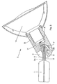
- the luminaire partially shown in the figures consists of a holder 1 and a luminaire head 2 (functional part) arranged thereon via a ball-and-socket joint.
- the ball-bearing part 3 of the joint is firmly anchored at one end 3a in the holder 1, the other end 3b, which the ball of Joint forms, is mounted in the plastic housing 4 of the lamp head 2.
- This ball-bearing part 3 of the joint is provided along its longitudinal axis A with a bore 5 in which, electrically insulated from the wall, a phase of an electrical current conductor in the form of a pin 6 made of electrically conductive material runs.
- the other phase is formed by the wall itself.
- the one contact element 7 consists of a curved spring strip which forms approximately a 1/4 circle and interacts with the pin 6 which extends in the bore 5 and protrudes beyond the spherical surface.
- the lamp head 2 is pivoted by approximately 90 about an axis B which is perpendicular to the longitudinal axis A of the part 3 carrying the ball and runs through the center of the ball, one end of the pin 6 slides along the contact element 7.
- the second contact element 8 is designed as a shell and lies with its concave side against the ball of the joint. This shell is pressed by means of a spring 9 against the ball and thus also presses the ball against the bearing in the plastic housing 4 of the lamp head 2. The resulting friction causes the position of the lamp head 2 to be maintained in the predetermined position relative to the holder 1.
- An electrical connection 10 leads from the contact elements 7, 8 to socket contacts 11, 12 of a lamp holder 13, from where an electrical transition to the corresponding lamp 14, in this case a low volt halogen lamp with reflector.
- the lamp head 2 it is possible to adjust the lamp head 2 relative to the holder 1 in such a way that every point on a hemisphere can be reached.
- the head 2 may be any number of times back and hergeschwenkt and also rotated through 360 0 out the process without causing an interruption of the current transition between the holder and function in part by mechanical overloading of the electrical connection portion.
Landscapes
- Engineering & Computer Science (AREA)
- General Engineering & Computer Science (AREA)
- Pivots And Pivotal Connections (AREA)
- Arrangement Of Elements, Cooling, Sealing, Or The Like Of Lighting Devices (AREA)
- Fastening Of Light Sources Or Lamp Holders (AREA)
Abstract
Description
- Die Erfindung betrifft ein elektrisches Gerät, das aus einer Halterung und einem daran schwenk- und drehbar angeordneten Funktionsteil besteht. Beide Teile sind miteinander auch elektrisch verbunden.
- Bisher erfolgten elektrische Verbindungen zwischen zwei derart zueinander beweglichen Teilen, z.B. bei einer Leuchte mit einem an einem Halter beweglichen Leuchtenkopf, über ein entsprechend langes Kabel. Dies hat jedoch den Nachteil, daß sich beim Drehen des Funktionsteils (z.B. des Leuchtenkopfes) um mehr als 360° das Kabel um die Halterung aufwickelt und dieses bei unbedachter Handhabung u.U. mit der Zeit aus dem Funktionsteil (Leuchtenkopf) herausgerissen wird.
- Für einfachere Gelenke, bei denen das Funktionsteil am Halter z.B. nur drehbar angeordnet ist, sind auch Lösungen bekannt, die es ermöglichen, ohne zusätzliches Kabel eine elektrische Verbindung herzustellen. So ist im deutschen Gebrauchsmuster 82 28 798 beispielsweise eine Leuchte beschrieben, bei der die Halterung in einem Koaxialanschlußelement endet und der Leuchtenkopf Schleifkontakte (Gabel und Drahtbiigel) aufweist, die an den entsprechenden Phasen des Koaxialanschlußelements anliegen.
- Mit der Erfindung soll nun ein elektrisches Gerät geschaffen werden, bei dem das Funktionsteil gegenüber der Halterung sowohl drehbar als auch schwenkbar angeordnet ist, und die elektrische Verbindung zwischen beiden Teilen ohne lästiges Kabel erfolgt.
- Die der Erfindung zugrundeliegende Aufgabe wird dadurch gelöst, daß sowohl die mechanische als auch die elektrische Verbindung zwischen der Halterung und dem Funktionsteil über ein Kugelgelenk erfolgt, wobei die Kugel des Gelenks in einem Gehäuse des Funktionsteils aus Kunststoff gelagert ist und gleichzeitig mit elektrischen Kontaktelementen des Funktionsteils zusammenwirkt.
- Insbesondere ist das die Kugel tragende Teil des Gelenks mit einer durchgehenden Bohrung versehen, wobei die Wandung dieses Teils die eine Phase des elektrischen Stromleiters bildet und die andere Phase, elektrisch-isoliert gegenüber der Wandung, in der Bohrung verläuft. Die in der Bohrung verlaufende Phase besteht aus einem Stift aus elektrisch-leitendem Material und ragt etwas über die Kugeloberfläche hinaus. Die Spitze des Stiftes gleitet dann, wenn das Funktionsteil um eine Achse, die senkrecht zur Längsachse der Bohrung steht und durch den Mittelpunkt der Kugel verläuft, geschwenkt wird, an einem vorteilhafterweise gebogenen, aus einem federnden Material bestehenden Kontaktelement entlang.
- Das andere Kontaktelement ist als Schale ausgebildetEs liegt mit seiner konkaven Seite an der Kugeloberfläche an und ermöglicht so ein freies Drehen des Funktionsteils um die Längsachse des die Kugel tragenden Teils des Kugelgelenks und gleichzeitig das Schwenken um oben genannte Schwenkachse. Die Schale wird durch eine Feder gegen die Kugel gedrückt und damit wird auch die Kugel gegen die Lagerung im Gehäuse des Funktionsteils gepreßt. Die dadurch entstehende Reibung bewirkt ein Beibehalten der Lage des Funktionsteils in vorgegebener Stellung zur Halterung.
- Je nachdem, welche Spannung und Stromstärke über das Kugelgelenk übertragen werden soll, ist die Isolierung zwischen der einen und der anderen Phase zu dimensionieren. Bei höher angelegter Spannung ab 24 V muß auch darauf geachtet werden, daß die stromführenden Teile des elektrischen Gerätes vor Berühren gesichert sind. Diese mechanische und elektrische Verbindung zwischen zwei Teilen ist bei jedem beliebigen elektrischen Gerät anwendbar.
- Zum besseren Verständnis wird die Erfindung anhand einer Leuchte erläutert. Ein Ausführungsbeispiel einer solchen Leuchte ist in den Figuren dargestellt und wird im folgenden näher beschrieben. Es zeigt:
- Figur 1 eine Teilansicht der Halterung einer Leuchte mit einem daran schwenk- und drehbar angeordneten Leuchtenkopf im Schnitt;
- Figur 2 eine um 900 gedrehte Seitenansicht der Halterung nach Figur 1, jedoch mit um 45° geschwenktem Leuchtenkopf im Schnitt.
- Die in den Figuren teilweise dargestellte Leuchte besteht aus einer Halterung 1 und einem daran über ein Kugelgelenk dreh- und schwenkbar angeordneten Leuchtenkopf 2 (Funktionsteil). Das die Kugel tragende Teil 3 des Gelenks ist mit einem Ende 3a in der Halterung 1 fest verankert, das andere Ende 3b, das die Kugel des Gelenks formt, ist in dem Kunststoffgehäuse 4 des Leuchtenkopfes 2 gelagert.
- Dieses die Kugel tragende Teil 3 des Gelenks ist entlang seiner Längsachse A mit einer Bohrung 5 versehen, in der, elektrisch-isoliert gegenüber der Wandung, die eine Phase eines elektrischen Stromleiters in Form eines Stiftes 6 aus elektrisch-leitendem Material verläuft. Die andere Phase wird durch die Wandung selbst gebildet.
- Zur Stromabnahme sind im Leuchtenkopf 2 Kontaktelemente 7, 8 vorgesehen. Das eine Kontaktelement 7 besteht aus einem gebogenen Federstreifen, der etwa einen 1/4-Kreis bildet und mit dem in der Bohrung 5 verlaufenden und über die Kugeloberfläche hervorstehenden Stift 6 zusammenwirkt. Bei Schwenken des Leuchtenkopfes 2 um etwa 90 um eine Achse B, die senkrecht zur Längsachse A des die Kugel tragenden Teils 3 steht und durch den Kugelmittelpunkt verläuft, gleitet das eine Ende des Stiftes 6 an dem Kontaktelement 7 entlang.
- Das zweite Kontaktelement 8 ist als Schale ausgebildet und liegt mit seiner konkaven Seite an der Kugel des Gelenks an. Diese Schale wird mittels einer Feder 9 gegen die Kugel gedrückt und drückt somit ebenfalls die Kugel gegen die Lagerung im Kunststoffgehäuse 4 des Leuchtenkopfes 2. Die dadurch entstandene Reibung bewirkt, daß die Stellung des Leuchtenkopfes 2 in der vorgegebenen Lage zur Halterung 1 beibehalten wird.
- Von den Kontaktelementen 7, 8 führt eine elektrische Verbindung 10 zu Fassungskontakten 11, 12 einer Lampenfassung 13, von wo aus ein elektrischer Übergang zu entsprechender Lampe 14, in diesem Fall einer Niedervolt-Halogenglühlampe mit Reflektor, erfolgt.
- Nach der Erfindung ist es möglich, den Leuchtenkopf 2 gegenüber der Halterung 1 derart einzustellen, daß jeder Punkt auf einer Halbkugel erreicht werden kann. Der Leuchtenkopf 2 kann dabei beliebig oft hin- und hergeschwenkt und auch über 3600 hinaus gedreht werden, ohne daß es zu einer Unterbrechung des Stromübergangs zwischen Halterung und Funktionsteil durch mechanische Überlastung des elektrischen Verbindungsteils kommt.
Claims (9)
Applications Claiming Priority (2)
| Application Number | Priority Date | Filing Date | Title |
|---|---|---|---|
| DE19843411976 DE3411976A1 (de) | 1984-03-30 | 1984-03-30 | Elektrisches geraet, bestehend aus einer halterung und einem daran schwenk- und drehbar angeordneten funktionsteil |
| DE3411976 | 1984-03-30 |
Publications (3)
| Publication Number | Publication Date |
|---|---|
| EP0156290A2 true EP0156290A2 (de) | 1985-10-02 |
| EP0156290A3 EP0156290A3 (en) | 1988-03-02 |
| EP0156290B1 EP0156290B1 (de) | 1991-08-28 |
Family
ID=6232176
Family Applications (1)
| Application Number | Title | Priority Date | Filing Date |
|---|---|---|---|
| EP85103174A Expired - Lifetime EP0156290B1 (de) | 1984-03-30 | 1985-03-19 | Leuchte mit schwenkbarem Leuchtenkopf |
Country Status (2)
| Country | Link |
|---|---|
| EP (1) | EP0156290B1 (de) |
| DE (2) | DE3411976A1 (de) |
Cited By (3)
| Publication number | Priority date | Publication date | Assignee | Title |
|---|---|---|---|---|
| GB2220307A (en) * | 1988-04-15 | 1990-01-04 | Marlin Lighting Limited | "Articulated support for a lamp or the like" |
| EP0475323A3 (en) * | 1990-09-11 | 1992-04-22 | Artemide S.P.A. | Lamp, particularly a table lamp |
| US9115878B2 (en) | 2012-11-08 | 2015-08-25 | Blackbeam Llc | Spotlight with clamp |
Families Citing this family (3)
| Publication number | Priority date | Publication date | Assignee | Title |
|---|---|---|---|---|
| DE9419027U1 (de) * | 1994-11-14 | 1995-04-13 | LTS Licht & Leuchten GmbH, 88069 Tettnang | Lampenhalterung |
| DE19741038A1 (de) * | 1997-09-18 | 1999-03-25 | Hella Kg Hueck & Co | Leuchte für Fahrzeuge |
| CN118202191A (zh) | 2021-10-28 | 2024-06-14 | 昕诺飞控股有限公司 | 定向照明装置 |
Family Cites Families (5)
| Publication number | Priority date | Publication date | Assignee | Title |
|---|---|---|---|---|
| DE23604C (de) * | A. W. BREWT-NALL in Warrington, County of Lancaster | Neuerungen in der Aufhängung elektrischer Lampen und Leitungen | ||
| DE1069288B (de) * | 1959-11-19 | |||
| US3278203A (en) * | 1964-02-05 | 1966-10-11 | Snyder Mfg Company | Swivel connector for lamps and the like |
| DE1489318A1 (de) * | 1965-06-23 | 1969-03-20 | Frankl & Kirchner | Haushalts- und Industrieleuchte |
| DE8228798U1 (de) * | 1982-10-13 | 1984-03-22 | Patent-Treuhand-Gesellschaft für elektrische Glühlampen mbH, 8000 München | Leseleuchte |
-
1984
- 1984-03-30 DE DE19843411976 patent/DE3411976A1/de not_active Withdrawn
-
1985
- 1985-03-19 DE DE8585103174T patent/DE3583879D1/de not_active Expired - Lifetime
- 1985-03-19 EP EP85103174A patent/EP0156290B1/de not_active Expired - Lifetime
Cited By (5)
| Publication number | Priority date | Publication date | Assignee | Title |
|---|---|---|---|---|
| GB2220307A (en) * | 1988-04-15 | 1990-01-04 | Marlin Lighting Limited | "Articulated support for a lamp or the like" |
| GB2220307B (en) * | 1988-04-15 | 1992-10-14 | Marlin Lighting Limited | Articulated support for a lamp or the like |
| EP0475323A3 (en) * | 1990-09-11 | 1992-04-22 | Artemide S.P.A. | Lamp, particularly a table lamp |
| US5235500A (en) * | 1990-09-11 | 1993-08-10 | Artemide S.P.A. | Lamp, particularly a table lamp |
| US9115878B2 (en) | 2012-11-08 | 2015-08-25 | Blackbeam Llc | Spotlight with clamp |
Also Published As
| Publication number | Publication date |
|---|---|
| DE3583879D1 (de) | 1991-10-02 |
| EP0156290A3 (en) | 1988-03-02 |
| DE3411976A1 (de) | 1985-10-10 |
| EP0156290B1 (de) | 1991-08-28 |
Similar Documents
| Publication | Publication Date | Title |
|---|---|---|
| EP1096606A1 (de) | Anschlussklemme | |
| DE3818078C2 (de) | Elektrische Steckvorrichtung mit Phasenwahl | |
| EP2577805A1 (de) | Kontaktelement für steckeranordnung | |
| WO2019201390A1 (de) | Geschirmtes steckverbindermodul für einen modularen industriesteckverbinder | |
| DE2441318C2 (de) | Sicherheitsvorrichtung für elektrische Verbindungsvorrichtungen | |
| WO1981001082A1 (fr) | Dispositif de couplage electrique | |
| EP0156290A2 (de) | Leuchte mit schwenkbarem Leuchtenkopf | |
| CH617294A5 (en) | Electric busbar with a snap-mounted connector | |
| DE2159202A1 (de) | Taschenleuchte oder aehnlicher stromverbraucher | |
| EP2551585A1 (de) | Kugelgelenk mit Stromdurchführung für eine Gelenkleuchte | |
| DE4018978A1 (de) | Schiebeschalter | |
| DE8409925U1 (de) | Elektrisches Gerät, bestehend aus einer Halterung und einem daran schwenk- und drehbar angeordneten Funktionsteil | |
| DE3877371T2 (de) | Elektrischer steckverbinder. | |
| EP1150399B1 (de) | Mehrpoliger elektrischer Anschlussverbinder | |
| EP0795216A1 (de) | Funktionskleinspannungs-stromspeiseeinrichtung | |
| WO1982003723A1 (en) | Electric contact,particularly for printed circuits of small electric appliances | |
| DE69403528T2 (de) | Mehrrichtungsklemmme eines Lichtbogenelektrodenhalters mit einem in den Griff eingefügten Hebel | |
| EP0352606B1 (de) | Lampenanordnung | |
| AT512697B1 (de) | Drehbare Leuchtmittelhalterung sowie Leuchte | |
| DE102010013946A1 (de) | Kugelgelenk mit Stromdurchführung für eine Gelenkleuchte | |
| DE19752617A1 (de) | Anordnung in Verbindung mit einer Stromabnahmevorrichtung eines Stromschienensystems | |
| EP0930673B1 (de) | Transformationseinrichtung und Steckeranordnung | |
| DE4322407C1 (de) | Prüf- oder Meßkopf für elektrische Prüf- und/oder Meßgeräte | |
| DE8116614U1 (de) | Federklemme zum Anschluß isolierter elektrischer Leiter | |
| DE102017131062B3 (de) | Steckdose |
Legal Events
| Date | Code | Title | Description |
|---|---|---|---|
| PUAI | Public reference made under article 153(3) epc to a published international application that has entered the european phase |
Free format text: ORIGINAL CODE: 0009012 |
|
| AK | Designated contracting states |
Designated state(s): BE DE FR IT |
|
| 17P | Request for examination filed |
Effective date: 19860208 |
|
| PUAL | Search report despatched |
Free format text: ORIGINAL CODE: 0009013 |
|
| AK | Designated contracting states |
Kind code of ref document: A3 Designated state(s): BE DE FR IT |
|
| 17Q | First examination report despatched |
Effective date: 19890529 |
|
| GRAA | (expected) grant |
Free format text: ORIGINAL CODE: 0009210 |
|
| AK | Designated contracting states |
Kind code of ref document: B1 Designated state(s): BE DE FR IT |
|
| REF | Corresponds to: |
Ref document number: 3583879 Country of ref document: DE Date of ref document: 19911002 |
|
| ITF | It: translation for a ep patent filed | ||
| ET | Fr: translation filed | ||
| PLBE | No opposition filed within time limit |
Free format text: ORIGINAL CODE: 0009261 |
|
| STAA | Information on the status of an ep patent application or granted ep patent |
Free format text: STATUS: NO OPPOSITION FILED WITHIN TIME LIMIT |
|
| 26N | No opposition filed | ||
| PGFP | Annual fee paid to national office [announced via postgrant information from national office to epo] |
Ref country code: BE Payment date: 19960319 Year of fee payment: 12 |
|
| PGFP | Annual fee paid to national office [announced via postgrant information from national office to epo] |
Ref country code: FR Payment date: 19960328 Year of fee payment: 12 |
|
| PG25 | Lapsed in a contracting state [announced via postgrant information from national office to epo] |
Ref country code: BE Effective date: 19970331 |
|
| BERE | Be: lapsed |
Owner name: PATENT-TREUHAND-G.- FUR ELEKTRISCHE GLUHLAMPEN M. Effective date: 19970331 |
|
| PG25 | Lapsed in a contracting state [announced via postgrant information from national office to epo] |
Ref country code: FR Free format text: LAPSE BECAUSE OF NON-PAYMENT OF DUE FEES Effective date: 19971128 |
|
| REG | Reference to a national code |
Ref country code: FR Ref legal event code: ST |
|
| PGFP | Annual fee paid to national office [announced via postgrant information from national office to epo] |
Ref country code: DE Payment date: 20020521 Year of fee payment: 18 |
|
| PG25 | Lapsed in a contracting state [announced via postgrant information from national office to epo] |
Ref country code: DE Free format text: LAPSE BECAUSE OF NON-PAYMENT OF DUE FEES Effective date: 20031001 |