EP0156334A2 - Méthode et dispositif de simulation (tête artificielle électronique) pour la simulation des caractéristiques de transmission de l'oreille en champ libre - Google Patents
Méthode et dispositif de simulation (tête artificielle électronique) pour la simulation des caractéristiques de transmission de l'oreille en champ libre Download PDFInfo
- Publication number
- EP0156334A2 EP0156334A2 EP19850103441 EP85103441A EP0156334A2 EP 0156334 A2 EP0156334 A2 EP 0156334A2 EP 19850103441 EP19850103441 EP 19850103441 EP 85103441 A EP85103441 A EP 85103441A EP 0156334 A2 EP0156334 A2 EP 0156334A2
- Authority
- EP
- European Patent Office
- Prior art keywords
- outer ear
- elements
- circuit
- pass
- ear
- Prior art date
- Legal status (The legal status is an assumption and is not a legal conclusion. Google has not performed a legal analysis and makes no representation as to the accuracy of the status listed.)
- Granted
Links
Images




Classifications
-
- H—ELECTRICITY
- H04—ELECTRIC COMMUNICATION TECHNIQUE
- H04R—LOUDSPEAKERS, MICROPHONES, GRAMOPHONE PICK-UPS OR LIKE ACOUSTIC ELECTROMECHANICAL TRANSDUCERS; ELECTRIC HEARING AIDS; PUBLIC ADDRESS SYSTEMS
- H04R5/00—Stereophonic arrangements
- H04R5/027—Spatial or constructional arrangements of microphones, e.g. in dummy heads
-
- G—PHYSICS
- G06—COMPUTING OR CALCULATING; COUNTING
- G06G—ANALOGUE COMPUTERS
- G06G7/00—Devices in which the computing operation is performed by varying electric or magnetic quantities
- G06G7/48—Analogue computers for specific processes, systems or devices, e.g. simulators
- G06G7/60—Analogue computers for specific processes, systems or devices, e.g. simulators for living beings, e.g. their nervous systems ; for problems in the medical field
-
- G—PHYSICS
- G06—COMPUTING OR CALCULATING; COUNTING
- G06J—HYBRID COMPUTING ARRANGEMENTS
- G06J1/00—Hybrid computing arrangements
Definitions
- the invention is based on a simulation method and a device according to the preamble of the main claim and the first device claim.
- the attempt to replace subsystems of a human outer ear model with electroacoustic circuits is known; for example, to simulate ear signals during headphone playback, which can occur with free field sound from any direction of sound.
- the invention is therefore based on the object to enter new territory here and to create an outer ear simulator as a so-called electronic artificial head, which is capable of a stepless directional adjustment without great effort, taking into account the human outer ear transmission properties, by amount and phase for all frequencies deliver, and which works in spite of the simplified structure with particularly high accuracy, that is, carries out the simulation so that the transmission properties of the electroacoustic equivalent circuit of the outer ear correspond practically identically to those of the human outer ear in free-field sound.
- the invention solves this problem with the characterizing features of the main claim and the characterizing features of the first device claim and has the advantage that corresponding ear signals can be generated with little effort in any direction of sound incidence in the free field, which can be used for headphone reproduction. This enables the realization of a natural sound image. It is also advantageous that, although, as is known to the person skilled in the art, outer ear transmission functions in particular have particularly complicated structures, the circuitry necessary for the practical implementation of the outer ear simulator according to the invention parts are limited to transit times, simple filters, high and low passes and resonance systems, if necessary.
- the parameters required for setting the circuits during operation can be determined directly from physically predetermined geometric dimensions using a model for the analytical description of the outer ear transmission properties. For the various directions of incidence of the sound, only a few filter parameters of the model of the electronic artificial head represented by an electronic circuit change in addition to the transit times.
- the electronic artificial head according to the invention generates ear signals familiar to the ear, so that on the one hand the in-head localization is avoided and on the other hand the setting of any hearing event directions is possible.
- the electronic artificial head it is possible with the electronic artificial head to spatially correctly mix signals from support microphones with the head-related recording.
- the signals of individual sound sources may be transcoded as through the use of the electronic artificial head that the whole can be utilized to human hearing range available for the production of handset e ignissen in Head-related playback.
- the direction of the hearing event can also be changed during a recording, so that movements of a sound source can be simulated.
- the loudspeaker compatibility of the electronic artificial head is comparable to artificial head recording systems, since both systems have or approximate free field transmission properties that are equivalent to one another.
- outer ear simulator according to the invention can also be coupled to an external computer via an interface, so that the individual transfer functions of test subjects or else the effect of hearing aids (HDO devices, in-the-ear devices), anomaly of the auricle or change in the eardrum impedance are electrically simulated can be.
- the basic idea of the present invention is to divide the physical causes of the outer ear transmission properties by differentiation and tracing back to predetermined, then simplified acoustic elements, for example the upper body, shoulder, head, auricle with cavum conchae cavity, ear canal and eardrum; All of these bodies have different influences on the outer ear transmission properties depending on the frequency, depending on their geometric dimensions, the resulting transfer function of the outer ear then being composed of the complex superimpositions of the resonances, reflections and diffraction waves caused by all partial bodies.
- Direction-dependent features are essentially determined by the elements, upper body, shoulder and auricular rim. Although it is possible to calculate such dependencies in principle (using KIRCHHOFF's diffraction integral, derived from GREEN's theorem), it is unsuitable for a descriptive representation, but for describing the mean outer ear transmission function and its simulation in a model, as by aimed at the invention is needed.
- the invention therefore does not approach the solution of the problem empirically, but begins with the consideration and basis of the mathematically effectively determined, complex diffraction and reflection relationships and the resulting transfer functions, which are converted into a (simplified) model by analytical consideration, which can be represented by electrical circuits, whereby, for example, the auricle or head is then represented by the first mathematical consideration of the superposition of several diffraction bodies in the form of certain circuits, with a complex addition of the respective reflected and diffracted sound components simulated by the electrical circuit blocks for the overall outer ear transmission function the corresponding parts or areas of the body.
- analytical consideration which can be represented by electrical circuits, whereby, for example, the auricle or head is then represented by the first mathematical consideration of the superposition of several diffraction bodies in the form of certain circuits, with a complex addition of the respective reflected and diffracted sound components simulated by the electrical circuit blocks for the overall outer ear transmission function the corresponding parts or areas of the body.
- a different level is taken into account by an
- Such a transfer function is approximated with a good approximation by a transit time in connection with a resonance system, as follows: where V n corresponds to the gain, Q n the quality and f on the resonance frequency of the opening n and the parameters of the resonance system - resonance frequency, quality, gain - are functionally related to the geometrical dimensions - radius and depth - of the auricle openings.
- the invention is therefore based on the knowledge that the external, acoustically effective geometry of a human being has a mathematically at least good approximation to the measured outer ear transfer function. Starting from average geometric dimensions, it is therefore possible in this way to determine an average outer ear transfer function for each direction of sound incidence without additional effort, which is suitable for those required for human hearing Transmission properties, since all the features required for the signal analysis and pattern recognition processes in the ear are taken into account due to the physical connection of the outer ear and its transmission properties. The realization is then possible by the assumption that these mathematically describable physical causes of the outer ear transmission properties can be approximated with a model that is based on systems known from telecommunications (high and low passes, delay elements, resonance elements and the like). This model allows the outer ear transfer function to be approximated for all sound incidence directions directly on the basis of physical parameters by varying a few parameters.
- the system outer ear with its direction-dependent transmission properties describes, in the communications technology sense, the frequency-dependent distortions that the sound signals experience as a function of the sound incidence direction when they are recoded into ear signals for the message receiver "human hearing".
- FIG. 3 of the direction-determining part of an outer ear simulator 10 - only one channel - the division by dash-dotted lines approximating circuit blocks for the head area at 10a, for the auricle area at 10b and for the area Area shoulder and upper body at 10c is shown.
- the cut-off frequencies of the high and low passes, the amounts of the transit time and the coefficients are determined directly from the parameters head size, sound incidence direction and position of the ear canal entrance.
- head the influence of the diffraction body shoulder (with the elements K S , HP S , P s and TP S ), upper body (K O ' HP O , T O and TP O ) and -
- the table shown on thecho whonsei t e concerns determined by measuring geometric data of six subjects, these data may as shown in FIG as geometric mean values with reference to the parameters of the individual approximation elements. 3, and the calculation of the circuit elements are applied.
- the values of the averaged geometric parameters can be permanently programmed to emulate mean outer ear transmission functions.
- Another example head With
- the influence of the direction-independent elements of the ear canal and carvum conchae cavity must be determined.
- the resonance property of this cavity can be approximated very well by bandpass systems in the form of series resonant circuits.
- the parameters (resonance frequency, quality and amplification) are also functionally related to the geometric dimensions of the cavity.
- the ear canal can be understood as a tube with a complex firing impedance, the eardrum impedance. To a good approximation, this system is described by a model consisting of transit time, high pass and coefficient.
- ear signals can be generated via the outputs for the free-field simulation, which correspond to the ear signals of a "middle" test person for the set sound incidence directions.
- the second output, designated 14b in FIG. 1, -14a is the free-field equalized output - is used to emulate the free-field outer ear transmission functions.
- the parameters of the circuit parts and - Blocks such as the size of a transit time or cut-off frequency of a low-pass filter or the like, can be determined directly with the aid of a model for the analytical description of the outer ear transmission properties from physically predetermined geometric dimensions, namely from the table given above, with the further, very significant conclusion that by Varying or changing such or in any case predetermined parameters of the circuit blocks here, and as can be understood immediately, completely continuously opens up the possibility of generating the corresponding ear signals c for each direction of sound incidence in the horizontal and median plane, so that With such an electronic artificial head, a system is available which provides corresponding ear signals for any sound incidence directions in a free field sound system
- FIG. 1 which comprises coefficients, low-pass, high-pass, all-pass, band-pass, adder, resonance elements and the like only for one channel combined by circuit blocks, only the runtimes for the different sound incidence directions only change few filter parameters. It is therefore also possible to simulate the transfer function for a sound incidence direction by determining these only a few parameters.
- the individual circuit blocks are designated in FIG. 1 for the head region with 10a ', for the ear cup and border with 10b' and for the shoulder and upper body with 10c '; an adder effecting the additive superimposition of the respective complex partial transmission functions bears the reference number 15.
- the circuit block of the direction-independent part comprises the areas of the ear canal and cavum conchae and is designated by 16.
- a further advantageous embodiment in the present invention is that all the runtimes occurring in the outer ear model are combined in a basic runtime circuit block 17 connected upstream of the circuit blocks 10a ', 10b' and 10c ', which represents and implements the required signal delays and runtimes.
- the present invention draws a digital realization of the high-quality construction Runtimes into consideration, which in principle take place in such a way that all the runtime elements assigned to the respective sub-models or circuit element chains are arranged as shown in FIG. 1, that is to say they are drawn in front of the individual other circuits, which makes it possible to use only one analog / Get by digital implementation.
- a 16-bit AD / converter is used for the basic runtime block 17, which operates at a sampling rate of 44 kHz, for example, which is sufficiently high.
- the quantized samples are read into a shift register after the conversion.
- the delay time is then determined by the time difference between writing and reading out different memory locations, which is controlled by a microprocessor, which is to be explained below and effects central control of the individual elements. Due to the short memory access times, it is possible to read out all memory locations required for runtime simulation (8 runtimes per channel - there are left and right channels) during a sampling period. With a fast DA / converter, the delayed samples can be output again in time-division multiplexing. Based on this concept, only one or two DA / converters (one converter for each channel) are then necessary.
- the filters and coefficients necessary for the simulation are then preferably implemented with the help of controllable operational amplifiers, which further will be explained below.
- a digital filter implementation - for example with fast signal processors - is also within the scope of the invention, but it is advisable, at least for the time being, in particular for cost and effort reasons.
- the electronic artificial head (outer ear simulator) forming the invention is preferably under a central control, which considerably simplifies practical handling;
- a microprocessor 18 is provided, in which, for example, the values of the averaged geometric parameters can also be permanently programmed, which are required for emulating mean outer ear transmission functions.
- the corresponding control parameters can then be calculated by the processor 18 and transferred directly to the controllable circuit blocks.
- FIG. 2a shows a free field outer ear transmission function (I) simulated according to the invention - here without upper body simulation - compared to an effective one measured, i.e. empirically determined transfer function, as shown in (II).
- FIG. 2b shows the simulation of individual acoustically effective parameters, to be referred to as free-field partial outer ear transmission functions, namely for the area of the ear canal at (1), the area of the shoulder and pinna border at (2) and the cavum conchae at (3);
- the outer ear transfer function (I) of Figure 2a is then composed of these two partial courses.
- the individual circuit elements of FIG. 3 represent the head, auricle border and shoulder / upper body areas of the circuit blocks of FIG. 1 in more detail, they connect to the basic runtime block 17 realized with digital elements and each contain individual, not yet mentioned addition elements 15a, 15b, 15c, 15d with the end adder 15 'with the output connection 20 leading to the direction-independent elements.
- the circuit elements in FIG. 3 represent the analog part of the microprocessor-controlled outer ear simulator, for realizing the coefficients, the high and low passes and the adders summarizing their output signals.
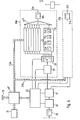
- FIG. 4 represents the basic circuit diagram of a possible form of implementation of an outer ear simulator according to the present invention, with a block 21 containing operating and input elements and display elements, assigned to the microprocessor system 18 ', to which a central time control 22 is also assigned or contained in it.
- the microprocessor influences the parameters of, for example, eight analog circuit channels 24 present here, which operate with their outputs on the summation element 15 ′′.
- the analog circuit channels 24 contain first and third order low and high pass filters 24a, 24b, bandpasses 24c and so-called coefficient elements 24d with a gain of - 1 ... + 1.
- the delay elements for the respective channels are realized as digital delay lines and arranged for this purpose so that only an AD / conversion to a digitization block 26 connected downstream of an input low-pass filter 25 is required.
- the quantized samples are read into a freely addressable memory 27 (delay memory RAM).
- the delay times that result between reading in and reading out the samples at different storage locations determine the time difference, the length of the register being determined by the maximum necessary delay time. Since a memory access is very short compared to the already mentioned sampling rate of preferably 44 kHz, all the sampling values necessary for the simulation of the different transit times can be read out in succession during a sampling period.
- the right channel area for example, is also designated 30a, and an associated left channel area is designated 30b;
- a low-pass filter 31a, 31b is also connected downstream of the adder elements 15 ', the right ear signal at the output 32a of the low-pass filter 31a and the left ear signal at the output 32b of the low-pass filter 31b.
- FIG. 5 A possible embodiment of a circuit element which can be designed as a low-pass filter or high-pass filter of the 1st order is shown in FIG. 5; the filter is constructed with the aid of a so-called "Operational Transconductance Amplifier - OTA" 33, which is connected as a controllable resistor, in which the forward steepness (transconductance) is the reciprocal of the gain and can be set with the aid of an externally fed direct current Is.
- the transfer function of either a low-pass or a high-pass results for the overall arrangement.
- a normal operational amplifier 34 is still connected downstream of the OTA 33; the control current results from the lower circuit part, the control voltage USt being fed to an operational amplifier 35 and reaching the OTA 33 via an FET transistor 36 at the output; only a capacitor C at the feedback branch and the resistors R3 and R4 in the input circuit for the inverting connection are essential to a feedback line 37 closed.
- a limit frequency proportional to the control current is then obtained in the case of such a circuit, for example from the following formula
- the circuit of FIG. 6 is a block diagram of an interface circuit for generating the control voltages U St. which can be removed at the output 38 of the circuit and are required for the parameter setting of the filters and coefficient elements.
- the microprocessor 18 '(FIG. 4) writes the parameter data word via a data bus line 39 into a data register 40. At its outputs, the data word is converted into a voltage by a digital / analog converter 41 with a downstream current-voltage converter 42 for example 0 ... -10 V implemented.
- sample + hold circuit 45 consists only of a storage capacitor C and a very high-resistance voltage follower 46 as an operational amplifier. If the capacitor C is charged, the channel is switched off again with an inhibit signal which is output by the address register 43. The whole process runs in the the same way cyclically for all other channels. In this way, the voltages across the holding capacitors C are refreshed in each case.
- An existing decoding logic 47 generates the loading pulses for the two registers 43 and 40 with the aid of address bus input lines 48 and control bus input lines 49 from the microprocessor system 18 '.
Landscapes
- Engineering & Computer Science (AREA)
- Physics & Mathematics (AREA)
- Theoretical Computer Science (AREA)
- Computer Hardware Design (AREA)
- General Physics & Mathematics (AREA)
- Mathematical Physics (AREA)
- Fuzzy Systems (AREA)
- Physiology (AREA)
- Neurosurgery (AREA)
- Neurology (AREA)
- General Health & Medical Sciences (AREA)
- Biomedical Technology (AREA)
- Automation & Control Theory (AREA)
- Evolutionary Computation (AREA)
- Health & Medical Sciences (AREA)
- Software Systems (AREA)
- Acoustics & Sound (AREA)
- Signal Processing (AREA)
- Stereophonic System (AREA)
- Details Of Audible-Bandwidth Transducers (AREA)
- Prostheses (AREA)
- Chair Legs, Seat Parts, And Backrests (AREA)
- Optical Fibers, Optical Fiber Cores, And Optical Fiber Bundles (AREA)
- Measurement Of Mechanical Vibrations Or Ultrasonic Waves (AREA)
- Apparatus For Radiation Diagnosis (AREA)
- Measurement And Recording Of Electrical Phenomena And Electrical Characteristics Of The Living Body (AREA)
- Measurement Of The Respiration, Hearing Ability, Form, And Blood Characteristics Of Living Organisms (AREA)
- Telephone Set Structure (AREA)
- Headphones And Earphones (AREA)
- Pharmaceuticals Containing Other Organic And Inorganic Compounds (AREA)
- Acyclic And Carbocyclic Compounds In Medicinal Compositions (AREA)
Priority Applications (1)
| Application Number | Priority Date | Filing Date | Title |
|---|---|---|---|
| AT85103441T ATE82812T1 (de) | 1984-03-27 | 1985-03-23 | Simulationsverfahren und vorrichtung (elektronischer kunstkopf) zur nachbildung der uebertragungseigenschaften des menschlichen aussenohrs bei freifeldbeschallung. |
Applications Claiming Priority (4)
| Application Number | Priority Date | Filing Date | Title |
|---|---|---|---|
| DE3411235 | 1984-03-27 | ||
| DE3411235 | 1984-03-27 | ||
| DE19853509358 DE3509358A1 (de) | 1984-03-27 | 1985-03-15 | Simulationsverfahren und vorrichtung (elektronischer kunstkopf) zur nachbildung der uebertragungseigenschaften des menschlichen aussenohrs bei freifeldbeschallung |
| DE3509358 | 1985-03-15 |
Publications (3)
| Publication Number | Publication Date |
|---|---|
| EP0156334A2 true EP0156334A2 (fr) | 1985-10-02 |
| EP0156334A3 EP0156334A3 (en) | 1988-01-27 |
| EP0156334B1 EP0156334B1 (fr) | 1992-11-25 |
Family
ID=25819754
Family Applications (1)
| Application Number | Title | Priority Date | Filing Date |
|---|---|---|---|
| EP85103441A Expired - Lifetime EP0156334B1 (fr) | 1984-03-27 | 1985-03-23 | Méthode et dispositif de simulation (tête artificielle électronique) pour la simulation des caractéristiques de transmission de l'oreille en champ libre |
Country Status (8)
| Country | Link |
|---|---|
| US (1) | US4672569A (fr) |
| EP (1) | EP0156334B1 (fr) |
| AT (1) | ATE82812T1 (fr) |
| AU (1) | AU573493B2 (fr) |
| BR (1) | BR8501394A (fr) |
| CA (1) | CA1237192A (fr) |
| DE (2) | DE3509358A1 (fr) |
| DK (1) | DK134285A (fr) |
Cited By (2)
| Publication number | Priority date | Publication date | Assignee | Title |
|---|---|---|---|---|
| WO1988007803A1 (fr) * | 1987-03-21 | 1988-10-06 | Head Stereo Gmbh Kopfbezogene Aufnahme- Und Wieder | Dispositif de filtrage de signaux acoustiques |
| US9887926B2 (en) | 2007-01-09 | 2018-02-06 | Koninklijke Philips N.V. | Wireless communication system |
Families Citing this family (7)
| Publication number | Priority date | Publication date | Assignee | Title |
|---|---|---|---|---|
| JP2935266B2 (ja) * | 1987-05-11 | 1999-08-16 | ジャンポルスキー、アーサー | 逆説的補聴器 |
| DE3737873C2 (de) * | 1987-11-07 | 1994-02-24 | Head Acoustics Gmbh | Verwendung von Hörsprechgarnituren zur Verbesserung der Sprachverständlichkeit in störschallerfüllter Umgebung |
| DE3922118A1 (de) * | 1989-07-05 | 1991-01-17 | Koenig Florian | Voll-richtungsvariable aussenohr-individualanpassung in der kopfbezogenen stereo-tonuebertragung |
| US5751817A (en) * | 1996-12-30 | 1998-05-12 | Brungart; Douglas S. | Simplified analog virtual externalization for stereophonic audio |
| FR2851877B1 (fr) * | 2003-02-28 | 2005-05-13 | Procede de mesure de fonctions de transfert acoustiques associees a la morphologie d'un individu | |
| US7680289B2 (en) * | 2003-11-04 | 2010-03-16 | Texas Instruments Incorporated | Binaural sound localization using a formant-type cascade of resonators and anti-resonators |
| DE10361954B4 (de) * | 2003-12-23 | 2007-08-30 | Oliver Klammt | Hörsystem und Verfahren zur Einstellung eines solchen, Verfahren zur Erkennung von charakteristischen Schallspektren, sowie entsprechende Computerprogramme und entsprechende computerlesbare Speichermedien |
Family Cites Families (8)
| Publication number | Priority date | Publication date | Assignee | Title |
|---|---|---|---|---|
| US3294909A (en) * | 1962-12-19 | 1966-12-27 | William F Caldwell | Electronic analog ear |
| US3432618A (en) * | 1965-07-12 | 1969-03-11 | Santa Rita Technology Inc | Method and system of analyzing the inner ear |
| US3570143A (en) * | 1968-11-08 | 1971-03-16 | Nasa | Waveform simulator |
| US3970787A (en) * | 1974-02-11 | 1976-07-20 | Massachusetts Institute Of Technology | Auditorium simulator and the like employing different pinna filters for headphone listening |
| US4105864A (en) * | 1975-07-17 | 1978-08-08 | Teledyne Industries, Inc. | Stereo and spaciousness reverberation system using random access memory and multiplex |
| US4316060A (en) * | 1980-01-04 | 1982-02-16 | Dbx, Inc. | Equalizing system |
| ATE14361T1 (de) * | 1981-10-20 | 1985-08-15 | Craigwell Ind Ltd | Hoerhilfegeraete. |
| US4581758A (en) * | 1983-11-04 | 1986-04-08 | At&T Bell Laboratories | Acoustic direction identification system |
-
1985
- 1985-03-15 DE DE19853509358 patent/DE3509358A1/de not_active Withdrawn
- 1985-03-23 DE DE8585103441T patent/DE3586850D1/de not_active Expired - Fee Related
- 1985-03-23 AT AT85103441T patent/ATE82812T1/de not_active IP Right Cessation
- 1985-03-23 EP EP85103441A patent/EP0156334B1/fr not_active Expired - Lifetime
- 1985-03-25 US US06/715,651 patent/US4672569A/en not_active Expired - Fee Related
- 1985-03-25 DK DK134285A patent/DK134285A/da not_active Application Discontinuation
- 1985-03-26 CA CA000477523A patent/CA1237192A/fr not_active Expired
- 1985-03-27 BR BR8501394A patent/BR8501394A/pt unknown
- 1985-03-27 AU AU40430/85A patent/AU573493B2/en not_active Ceased
Cited By (3)
| Publication number | Priority date | Publication date | Assignee | Title |
|---|---|---|---|---|
| WO1988007803A1 (fr) * | 1987-03-21 | 1988-10-06 | Head Stereo Gmbh Kopfbezogene Aufnahme- Und Wieder | Dispositif de filtrage de signaux acoustiques |
| US9887926B2 (en) | 2007-01-09 | 2018-02-06 | Koninklijke Philips N.V. | Wireless communication system |
| US10652161B2 (en) | 2007-01-09 | 2020-05-12 | Koninklijke Philips N.V. | Wireless communication system |
Also Published As
| Publication number | Publication date |
|---|---|
| ATE82812T1 (de) | 1992-12-15 |
| DK134285D0 (da) | 1985-03-25 |
| AU573493B2 (en) | 1988-06-09 |
| DE3586850D1 (de) | 1993-01-07 |
| BR8501394A (pt) | 1985-11-26 |
| EP0156334B1 (fr) | 1992-11-25 |
| DE3509358A1 (de) | 1985-11-14 |
| DK134285A (da) | 1985-09-28 |
| EP0156334A3 (en) | 1988-01-27 |
| US4672569A (en) | 1987-06-09 |
| AU4043085A (en) | 1985-10-03 |
| CA1237192A (fr) | 1988-05-24 |
Similar Documents
| Publication | Publication Date | Title |
|---|---|---|
| DE69726262T2 (de) | Tonaufnahme- und -wiedergabesysteme | |
| DE68922885T2 (de) | Verfahren und Vorrichtung zur Schallbilderzeugung. | |
| DE4328620C1 (de) | Verfahren zur Simulation eines Raum- und/oder Klangeindrucks | |
| DE69522971T2 (de) | Binaurale Synthese, kopfbezogene Übertragungsfunktion, und ihre Verwendung | |
| DE60304358T2 (de) | Verfahren zur verarbeitung von audiodateien und erfassungsvorrichtung zur anwendung davon | |
| DE2244162C3 (de) | «system | |
| DE69525163T2 (de) | Tonaufnahme- und wiedergabesysteme | |
| DE69433258T2 (de) | Raumklangsignalverarbeitungsvorrichtung | |
| DE69417571T2 (de) | Vorrichtung zur verarbeitung von binauralen signalen | |
| DE69717678T2 (de) | Stereotonerweiterer | |
| DE69227091T2 (de) | Schaltung zur Mischung und Verdoppelung von niedrigen Tonfrequenzen | |
| DE102012017296A1 (de) | Erzeugung von Mehrkanalton aus Stereo-Audiosignalen | |
| EP0825800A2 (fr) | Méthode et appareil pour générer des signaux multi-audio d'un signal audio-mono | |
| EP0156334B1 (fr) | Méthode et dispositif de simulation (tête artificielle électronique) pour la simulation des caractéristiques de transmission de l'oreille en champ libre | |
| DE69610966T2 (de) | Digitales Filter und Tonwiedergabegerät damit | |
| DE1148269B (de) | Schaltungsanordnung zur Schallaufnahme und/oder Schallwiedergabe mit zwei Wiedergabekanaelen und Verfahren zur stereophonischen Schallaufzeichnung | |
| DE69707847T2 (de) | Vorrichtung zur vearbeitung von stereosignalen | |
| DE2344259C3 (de) | Mehrkanalsystem zur Aufnahme und Wiedergabe stereofoner Darbietungen | |
| EP0025509B1 (fr) | Procédé de transmission stéréophonique et moyens pour la mise en oeuvre de ce procédé | |
| DE102007011436B4 (de) | Vorrichtung und Verfahren zum Formen eines digitalen Audiosignals | |
| DE3737873C2 (de) | Verwendung von Hörsprechgarnituren zur Verbesserung der Sprachverständlichkeit in störschallerfüllter Umgebung | |
| DE112006002548T5 (de) | Vorrichtung und Verfahren zur Wiedergabe von virtuellem Zweikanal-Ton | |
| DE4440451C2 (de) | Richtungssteller für zweikanalige Stereofonie | |
| DE3640414C2 (de) | System zur Erzeugung eines Pseudo-Stereo-Effektes bei der Wiedergabe eines monophonen Klanges | |
| DE19628261A1 (de) | Verfahren und Vorrichtung zum elektronischen Einbetten von Richtungseinsätzen bei Zweikanal-Ton |
Legal Events
| Date | Code | Title | Description |
|---|---|---|---|
| PUAI | Public reference made under article 153(3) epc to a published international application that has entered the european phase |
Free format text: ORIGINAL CODE: 0009012 |
|
| AK | Designated contracting states |
Kind code of ref document: A2 Designated state(s): AT BE CH DE FR GB IT LI LU NL SE Designated state(s): AT BE CH DE FR GB IT LI LU NL SE |
|
| RAP1 | Party data changed (applicant data changed or rights of an application transferred) |
Owner name: HEAD STEREO GMBH , KOPFBEZOGENE AUFNAHME- UND WIED |
|
| PUAL | Search report despatched |
Free format text: ORIGINAL CODE: 0009013 |
|
| AK | Designated contracting states |
Kind code of ref document: A3 Designated state(s): AT BE CH DE FR GB IT LI LU NL SE |
|
| 17P | Request for examination filed |
Effective date: 19880722 |
|
| RAP1 | Party data changed (applicant data changed or rights of an application transferred) |
Owner name: HEAD ACOUSTICS GMBH KOPFBEZOGENE AUFNAHME- UND WIE |
|
| 17Q | First examination report despatched |
Effective date: 19891221 |
|
| RAP3 | Party data changed (applicant data changed or rights of an application transferred) |
Owner name: HEAD ACOUSTICS GMBH KOPFBEZOGENE AUFNAHME- UND WIE |
|
| GRAA | (expected) grant |
Free format text: ORIGINAL CODE: 0009210 |
|
| AK | Designated contracting states |
Kind code of ref document: B1 Designated state(s): AT BE CH DE FR GB IT LI LU NL SE |
|
| PG25 | Lapsed in a contracting state [announced via postgrant information from national office to epo] |
Ref country code: SE Effective date: 19921125 Ref country code: NL Effective date: 19921125 |
|
| REF | Corresponds to: |
Ref document number: 82812 Country of ref document: AT Date of ref document: 19921215 Kind code of ref document: T |
|
| REF | Corresponds to: |
Ref document number: 3586850 Country of ref document: DE Date of ref document: 19930107 |
|
| ITF | It: translation for a ep patent filed | ||
| ET | Fr: translation filed | ||
| PG25 | Lapsed in a contracting state [announced via postgrant information from national office to epo] |
Ref country code: LU Free format text: LAPSE BECAUSE OF NON-PAYMENT OF DUE FEES Effective date: 19930331 |
|
| GBT | Gb: translation of ep patent filed (gb section 77(6)(a)/1977) |
Effective date: 19930317 |
|
| NLV1 | Nl: lapsed or annulled due to failure to fulfill the requirements of art. 29p and 29m of the patents act | ||
| PLBE | No opposition filed within time limit |
Free format text: ORIGINAL CODE: 0009261 |
|
| STAA | Information on the status of an ep patent application or granted ep patent |
Free format text: STATUS: NO OPPOSITION FILED WITHIN TIME LIMIT |
|
| 26N | No opposition filed | ||
| PGFP | Annual fee paid to national office [announced via postgrant information from national office to epo] |
Ref country code: BE Payment date: 19950406 Year of fee payment: 11 |
|
| PGFP | Annual fee paid to national office [announced via postgrant information from national office to epo] |
Ref country code: AT Payment date: 19960325 Year of fee payment: 12 |
|
| PG25 | Lapsed in a contracting state [announced via postgrant information from national office to epo] |
Ref country code: BE Effective date: 19960331 |
|
| BERE | Be: lapsed |
Owner name: HEAD ACOUSTICS G.M.B.H. KOPFBEZOGENE AUFNAHME- UN Effective date: 19960331 |
|
| PGFP | Annual fee paid to national office [announced via postgrant information from national office to epo] |
Ref country code: GB Payment date: 19970305 Year of fee payment: 13 |
|
| PGFP | Annual fee paid to national office [announced via postgrant information from national office to epo] |
Ref country code: FR Payment date: 19970319 Year of fee payment: 13 |
|
| PG25 | Lapsed in a contracting state [announced via postgrant information from national office to epo] |
Ref country code: AT Effective date: 19970323 |
|
| PGFP | Annual fee paid to national office [announced via postgrant information from national office to epo] |
Ref country code: CH Payment date: 19970324 Year of fee payment: 13 |
|
| PG25 | Lapsed in a contracting state [announced via postgrant information from national office to epo] |
Ref country code: GB Free format text: LAPSE BECAUSE OF NON-PAYMENT OF DUE FEES Effective date: 19980323 |
|
| PG25 | Lapsed in a contracting state [announced via postgrant information from national office to epo] |
Ref country code: LI Free format text: LAPSE BECAUSE OF NON-PAYMENT OF DUE FEES Effective date: 19980331 Ref country code: FR Free format text: THE PATENT HAS BEEN ANNULLED BY A DECISION OF A NATIONAL AUTHORITY Effective date: 19980331 Ref country code: CH Free format text: LAPSE BECAUSE OF NON-PAYMENT OF DUE FEES Effective date: 19980331 |
|
| PGFP | Annual fee paid to national office [announced via postgrant information from national office to epo] |
Ref country code: DE Payment date: 19980406 Year of fee payment: 14 |
|
| GBPC | Gb: european patent ceased through non-payment of renewal fee |
Effective date: 19980323 |
|
| REG | Reference to a national code |
Ref country code: CH Ref legal event code: PL |
|
| REG | Reference to a national code |
Ref country code: FR Ref legal event code: ST |
|
| PG25 | Lapsed in a contracting state [announced via postgrant information from national office to epo] |
Ref country code: DE Free format text: LAPSE BECAUSE OF NON-PAYMENT OF DUE FEES Effective date: 20000101 |