EP0156359A2 - Machine à écrire électronique - Google Patents
Machine à écrire électronique Download PDFInfo
- Publication number
- EP0156359A2 EP0156359A2 EP85103567A EP85103567A EP0156359A2 EP 0156359 A2 EP0156359 A2 EP 0156359A2 EP 85103567 A EP85103567 A EP 85103567A EP 85103567 A EP85103567 A EP 85103567A EP 0156359 A2 EP0156359 A2 EP 0156359A2
- Authority
- EP
- European Patent Office
- Prior art keywords
- printing
- ribbon
- holding time
- key
- character keys
- Prior art date
- Legal status (The legal status is an assumption and is not a legal conclusion. Google has not performed a legal analysis and makes no representation as to the accuracy of the status listed.)
- Withdrawn
Links
Images


Classifications
-
- B—PERFORMING OPERATIONS; TRANSPORTING
- B41—PRINTING; LINING MACHINES; TYPEWRITERS; STAMPS
- B41J—TYPEWRITERS; SELECTIVE PRINTING MECHANISMS, i.e. MECHANISMS PRINTING OTHERWISE THAN FROM A FORME; CORRECTION OF TYPOGRAPHICAL ERRORS
- B41J29/00—Details of, or accessories for, typewriters or selective printing mechanisms not otherwise provided for
- B41J29/38—Drives, motors, controls or automatic cut-off devices for the entire printing mechanism
-
- B—PERFORMING OPERATIONS; TRANSPORTING
- B41—PRINTING; LINING MACHINES; TYPEWRITERS; STAMPS
- B41J—TYPEWRITERS; SELECTIVE PRINTING MECHANISMS, i.e. MECHANISMS PRINTING OTHERWISE THAN FROM A FORME; CORRECTION OF TYPOGRAPHICAL ERRORS
- B41J5/00—Devices or arrangements for controlling character selection
- B41J5/30—Character or syllable selection controlled by recorded information
- B41J5/44—Character or syllable selection controlled by recorded information characterised by storage of recorded information
Definitions
- the present invention relates to an electronic typewriter in which a printing ribbon is held at a printing position for a preset holding time after a printing operation.
- a character key of, e.g., alphanumeric characters, symbols, and the like is pressed
- a character code corresponding to the input alphanumeric character or symbol is generated and stored in a memory.
- the printing wheel is rotated by a printing wheel motor in accordance with the character code so that a type with the character designated by the character code is positioned to oppose printing paper set on a platen.
- the printing ribbon is set at a printing position between the type of the printing wheel and the paper.
- a carriage mounting a printing mechanism thereon is shifted horizontally so that the type of the printing wheel is positioned at the printing position on the paper.
- the printing ribbon in order to shorten a response time from a key operation to a printing operation, when the key operation is continuously performed, the printing ribbon is held at the printing position, and the printing wheel does not return to a home position every time the printing operation for one character code is completed.
- the ribbon returns to a rest position thereof and the printing wheel returns to the home position in order to allow the last character printed to be easily confirmed.
- the holding time is fixed at a predetermined value for each electronic typewriter.
- the electronic typewriter with a fixed holding time has the following problems.
- the printing ribbon may return to the rest position during printing of a word. Therefore, since the time for shifting the ribbon from the rest position to the printing position is added to the printing response time for the key operation, the overall printing speed is further decreased.
- an electronic typewriter comprising a plurality of character keys, a printing wheel having a plurality of types designated by these character keys, a holding time data generator for generating holding time data which can be arbitrarily set, a ribbon position setting circuit for selectively setting a printing ribbon at one of the printing and rest positions, and a control unit which, when detecting that one of the character keys is operated while the printing ribbon is set in the rest position, supplies a first control signal to the ribbon position setting circuit to move the printing ribbon to the printing position and then strike the type designated by the operated character key against a paper sheet through the printing ribbon, and which supplies a second control signal to the ribbon position setting circuit to return the printing ribbon to the rest position when no further key operation is detected for a predetermined period of time corresponding to the holding time data after the printing operation for the operated character key is completed.
- the holding time data from the holding time data generator can be arbitrarily changed, it is possible to arbitrarily set an interval from the time at which the printing operation for the operated character key is completed to the time at which the ribbon is returned to the rest position if no further character key operation is performed. Therefore, when the holding time is set long for a beginner, the problem of the ribbon undesirably returning to the rest position during one word printing can be effectively prevented. On the other hand, when the holding time is set short for a skilled operator, the time required for returning the ribbon to the rest position after printing can be shortened. In this manner, the electronic typewriter can be easily used, and can perform printing in accordance with the operator's skill.
- Fig. 1 is a plan view of an electronic typewriter according to an embodiment of the present invention.
- the electronic typewriter includes a housing 1, and a keyboard 2 provided on the front surface of the housing 1.
- a platen 3 for setting printing paper thereon is installed in an upper portion inside the housing 1.
- a printing mechanism is mounted on a carriage 4 which can be shifted along the platen 3.
- the printing mechanism includes a printing wheel 5 having types formed on distal ends of spokes thereof, a printing wheel motor (not shown) for driving the printing wheel 5, a printing ribbon 6, a ribbon feed motor (not shown), a ribbon position setting unit (not shown) using an electromagnet for vertically shifting a ribbon position, and a hammer solenoid 7 for making the type of the wheel 5 strike the printing paper through the ribbon 6.
- Various function keys including a code key 11 are arranged on the keyboard 2 in addition to alphabet keys 8, numeral keys 9, and a space key 10.
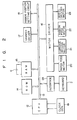
- Fig. 2 is a block diagram of the electronic typewriter shown in Fig. 1.
- the electronic typewriter includes a central processing unit (CPU) 12 for executing various calculations in accordance with key input data received from the keyboard 2 through an interface 2A, a ROM 14 connected to the CPU 12 through a data bus 13 for storing fixed data including rotational position data of the printing wheel 5 corresponding to respective character codes, and a RAM 15 backed up by a battery for temporarily storing variable data such as input character codes from the keyboard 2.
- the CPU 12 is connected through the data bus 13 to the keyboard 2 for inputting character codes, a motor driver 16 for driving various motors, a solenoid driver 17 for driving the hammer solenoid 7, and a ribbon position setting circuit 18.
- a clock signal from a clock generator 19 is supplied to a clock input terminal CK of the CPU 12.
- An interrupt signal generated from the generator 19 having a period TA of 1 msec is supplied to the interrupt input terminal INT of the CPU 12.
- the motor driver 16 is connected to a paper feed motor 20 coupled to the platen 3 for feeding the printing paper, a carriage motor 21 for shifting the carriage 4 along the platen 3, a ribbon feed motor 22 for feeding the printing ribbon 6, and a printing wheel motor 23 for rotating the wheel 5.
- the RAM 15 includes a printing data buffer area RAl for temporarily storing input character codes from the keyboard 2; a holding time table RA2 for storing holding time data HTl to HT9 representing a holding time during which the printing ribbon 6 and the printing wheel 5 are kept at positions opposing the printed character after the end of printing by the operation of the character key in the keyboard 2; a code flag area RA3 for storing a code flag representing that the code key 11 of the keyboard 2 is operated; an "S" flag area RA4 for storing an "S" flag representing that an "S” key of the alphabet keys 8 is operated; a time memory area RA5 for storing the present holding time TS; and a time counter RA6 for measuring time elapsed after the end of printing by operation of character keys such as the alphabet keys 8 and the numeral keys 9.
- a printing data buffer area RAl for temporarily storing input character codes from the keyboard 2
- a holding time table RA2 for storing holding time data HTl to HT9 representing a holding time during
- nine holding time data HT1 to HT9 representing holding times 0.3 to 2.7 seconds in 0.3 second increments are stored in indexes 1 to 9 of the holding time table RA2.
- the CPU 12 sets the required holding time TS in the time memory area RA5 from the holding time table RA2 in accordance with a flow chart shown in Fig. 4, and stores the character codes in the printing data buffer RAl. More specifically, when a key signal is supplied from the keyboard 2, the CPU 12 checks to see if the input key signal corresponds to the code key 11 in STEP 1. If it is YES in STEP 1, the CPU 12 sets the code flag of the area RA3 in the RAM 15 at "1". If it is NO in STEP 1, the CPU 12 checks in STEP 2 if the input key signal is generated by "S" key among the alphabet keys 8.
- the CPU 12 determines that the setting operation of the holding time starts, and sets the "S" flag of the area RA4 at "1".
- the CPU 12 detects that the code flag is not at "1”
- it determines that a normal character code has been supplied and stores a corresponding character code in the printing data buffer area RAl.
- the CPU 12 determines whether or not the operated key is one of the numeral keys 9 in STEP 3. If it is YES in STEP 3, the CPU 12 executes the operation designated by the operated key. For example, when the key operated is an alphabet key other than the "S" key, the CPU 12 stores the corresponding character code in the printing data buffer area RAl. On the other hand, when the operated key is a function key, the CPU 12 executes the operation designated by this key. When the operated key is any of "1" to "9" of the numeric keys 9, the CPU 12 checks to see if the "S" flag of the area RA4 is at "1" in STEP 4.
- the CPU 12 determines that the input numeral represents an index in the holding time table RA2, and reads out one of the holding time data HT1 to HT9 represented by the numeral and sets the holding time data in the time memory area RA5. Thereafter, the code and "S" flags-in the areas RA3 and RA4 are reset, thus ending the setting operation of the holding time. Note that in STEP 4, when the CPU 12 detects that the "S" flag in the area RA4 is not set at "l", it determines that the normal character code is supplied and stores the character code corresponding to the input numeral in the printing data buffer area RAl.
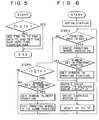
- the CPU 12 Every time an interrupt signal having the period TA (1 ms) is supplied from the clock generator 19 to the interrupt input terminal INT, the CPU 12 carries out the interrupt operation in accordance with a flow chart shown in Fig. 5. More specifically, when the interrupt signal of the period TA (1 ms) is supplied, the CPU 12 checks if the time data TC stored in the time counter RA6 in the RAM 15 is equal to or larger than the holding time data TS in the time memory area RA5. If it is NO, the CPU 12 sets the time data obtained by adding the period TA to the time data TC in the time counter RA6. When the CPU 12 detects TC > TS, it ends this interrupt routine without changing the time data TC in the time counter RA6.
- Fig. 6 shows a main control routine of the electronic typewriter shown in Fig. 2.
- the CPU 12 performs the initialization process.
- the CPU 12 checks to see if the printing data buffer area RAl stores a character code to be generated. If it is YES in STEP 5, the CPU 12 supplies drive data to the printing wheel motor 23 so as to rotate the printing wheel 5 to allow the type corresponding to the stored character code to oppose the printing paper set on the platen 3, i.e., the type is set at the printing position.
- the CPU 12 checks to see if the printing ribbon 6 is set at a position opposite to the character which has been printed, i.e., at the printing position.
- the CPU 12 When the CPU 12 detects that the ribbon 6 is not at the printing position but at the rest position, it supplies a control signal to the ribbon position setting circuit 18 to raise the ribbon 6 to the printing position. Thereafter, the CPU 12 supplies a drive signal to the solenoid driver 17 so as to drive the hammer solenoid 7, thereby printing the character corresponding to the character code on the paper. The CPU 12 drives the carriage motor 21 so as to shift the carriage 4 by one character to the next printing position. Thereafter, the time data TC in the time counter RA6 is set at . 0 . , i.e., the counter is reset, thus ending the printing operation with respect to one character code.
- the CPU 12 determines that the next key operation has not been performed. The CPU 12 then checks in STEP 6 if the time TC in the time counter RA6 has reached the holding time TS set in the time memory area RA5. If it is YES in STEP 6, the CPU 12 checks the position of the printing ribbon 6. When the ribbon 6 is at the printing position, the CPU 12 supplies a control signal to the ribbon position setting circuit 18 so as to move the ribbon 6 downward. Thereafter, the motor 23 is driven to return the printing wheel 5 to the home position. In this state, since the ribbon 6 is at the rest position and the wheel 5 is at the home position, a user can confirm the printed character.
- the present invention is not limited to the above embodiment.
- the time TC between two successive key operations reaches the holding time TS
- the ribbon 6 is shifted downward and the wheel 5 is returned to the home position.
- the time TC reaches the holding time TS only the ribbon 6 can be moved to the rest position to provide a similar effect.
- the ribbon 6 can be shifted to the rest position and thereafter the carriage 4 can be shifted to a position at which the printed characters or words can be confirmed instead of moving the ribbon 6 downward and returning the wheel 5 to the home position.
- the holding time data set in the holding time table RA2 in the RAM 15 can be changed as needed.
- the code key 11 and the "S" key are operated and thereafter one of the numeric keys 9 for designating an index corresponding to time data to be set is operated.
- appropriate function and alphabet keys can be used in place of the code key 11 and the "S' key.
- the holding time table RA2 can be omitted and desired holding time data can be stored in the time memory area RA5 by manually operating the numeric keys.
Landscapes
- Accessory Devices And Overall Control Thereof (AREA)
- Impression-Transfer Materials And Handling Thereof (AREA)
Applications Claiming Priority (2)
| Application Number | Priority Date | Filing Date | Title |
|---|---|---|---|
| JP57762/84 | 1984-03-26 | ||
| JP5776284A JPS60201981A (ja) | 1984-03-26 | 1984-03-26 | 電子タイプライタ− |
Publications (2)
| Publication Number | Publication Date |
|---|---|
| EP0156359A2 true EP0156359A2 (fr) | 1985-10-02 |
| EP0156359A3 EP0156359A3 (fr) | 1988-03-02 |
Family
ID=13064886
Family Applications (1)
| Application Number | Title | Priority Date | Filing Date |
|---|---|---|---|
| EP85103567A Withdrawn EP0156359A3 (fr) | 1984-03-26 | 1985-03-26 | Machine à écrire électronique |
Country Status (2)
| Country | Link |
|---|---|
| EP (1) | EP0156359A3 (fr) |
| JP (1) | JPS60201981A (fr) |
Cited By (1)
| Publication number | Priority date | Publication date | Assignee | Title |
|---|---|---|---|---|
| US4810117A (en) * | 1986-03-11 | 1989-03-07 | Brother Kogyo Kabushiki Kaisha | Printer with a ribbon lift mechanism having selective time intervals either in typewriter mode or in printer mode |
Family Cites Families (2)
| Publication number | Priority date | Publication date | Assignee | Title |
|---|---|---|---|---|
| DE2511138A1 (de) * | 1975-03-14 | 1976-09-30 | Hohner Ag Matth | Steuereinrichtung zum anheben und absenken eines farbbandes oder einer farbbandkassette an einer schreibmaschine oder druckeinrichtung |
| AU530568B2 (en) * | 1980-10-31 | 1983-07-21 | Canon Kabushiki Kaisha | Serial printing apparatus with memory and display |
-
1984
- 1984-03-26 JP JP5776284A patent/JPS60201981A/ja active Pending
-
1985
- 1985-03-26 EP EP85103567A patent/EP0156359A3/fr not_active Withdrawn
Cited By (1)
| Publication number | Priority date | Publication date | Assignee | Title |
|---|---|---|---|---|
| US4810117A (en) * | 1986-03-11 | 1989-03-07 | Brother Kogyo Kabushiki Kaisha | Printer with a ribbon lift mechanism having selective time intervals either in typewriter mode or in printer mode |
Also Published As
| Publication number | Publication date |
|---|---|
| EP0156359A3 (fr) | 1988-03-02 |
| JPS60201981A (ja) | 1985-10-12 |
Similar Documents
| Publication | Publication Date | Title |
|---|---|---|
| US4655620A (en) | Spelling error finding feature including an electronic spelling dictionary | |
| JPH0510234B2 (fr) | ||
| US3872959A (en) | Positioning typewriter | |
| US4548520A (en) | Electronic typewriter | |
| JPH0378266B2 (fr) | ||
| US4678351A (en) | Right margin zone hyphenation | |
| US3754631A (en) | Positioning typewriter | |
| EP0271321B1 (fr) | Appareil d'affichage pour machines à écrire | |
| EP0242951B1 (fr) | Machine à écrire avec une fonction de correction | |
| EP0117892A1 (fr) | Machine à écrire électronique | |
| US4695172A (en) | Printer with display for double-width character | |
| EP0185937B1 (fr) | Dispositif pour la mise en place de la tabulation pour une imprimante | |
| EP0047018B1 (fr) | Système pour contrôler une machine à marquer | |
| EP0121587B1 (fr) | Machine à écrire | |
| GB2224242A (en) | Ribbon-shifts co-ordinated with spelling checks in typewriters or like selective printers | |
| JPH0114432Y2 (fr) | ||
| JP2560297B2 (ja) | 出力装置 | |
| JPH0557918B2 (fr) | ||
| JPS6116881A (ja) | 電子タイプライタ− | |
| JPS6353042A (ja) | 記録装置 | |
| JPH0544045B2 (fr) | ||
| JPS62271747A (ja) | 印字装置 | |
| JPH0461777B2 (fr) | ||
| GB2128385A (en) | Reverse tab control system for typewriter | |
| JPS6151375A (ja) | 電子タイプライタ− |
Legal Events
| Date | Code | Title | Description |
|---|---|---|---|
| PUAI | Public reference made under article 153(3) epc to a published international application that has entered the european phase |
Free format text: ORIGINAL CODE: 0009012 |
|
| AK | Designated contracting states |
Designated state(s): DE FR GB SE |
|
| PUAL | Search report despatched |
Free format text: ORIGINAL CODE: 0009013 |
|
| STAA | Information on the status of an ep patent application or granted ep patent |
Free format text: STATUS: THE APPLICATION IS DEEMED TO BE WITHDRAWN |
|
| AK | Designated contracting states |
Kind code of ref document: A3 Designated state(s): DE FR GB SE |
|
| 18D | Application deemed to be withdrawn |
Effective date: 19870401 |
|
| RIN1 | Information on inventor provided before grant (corrected) |
Inventor name: TAKAHASHI, MAKOTO |