EP0156499B1 - Hauptzylindervorratsbehälter - Google Patents
Hauptzylindervorratsbehälter Download PDFInfo
- Publication number
- EP0156499B1 EP0156499B1 EP85301138A EP85301138A EP0156499B1 EP 0156499 B1 EP0156499 B1 EP 0156499B1 EP 85301138 A EP85301138 A EP 85301138A EP 85301138 A EP85301138 A EP 85301138A EP 0156499 B1 EP0156499 B1 EP 0156499B1
- Authority
- EP
- European Patent Office
- Prior art keywords
- compartments
- reservoir
- reservoir according
- connector means
- flange
- Prior art date
- Legal status (The legal status is an assumption and is not a legal conclusion. Google has not performed a legal analysis and makes no representation as to the accuracy of the status listed.)
- Expired
Links
- 239000012530 fluid Substances 0.000 claims description 12
- 239000000463 material Substances 0.000 claims description 8
- 238000000071 blow moulding Methods 0.000 claims description 6
- 238000002788 crimping Methods 0.000 claims description 3
- 230000015572 biosynthetic process Effects 0.000 claims description 2
- 239000000945 filler Substances 0.000 description 3
- 238000000465 moulding Methods 0.000 description 3
- 238000004519 manufacturing process Methods 0.000 description 2
- 239000004033 plastic Substances 0.000 description 2
- 229920003023 plastic Polymers 0.000 description 2
- 230000009977 dual effect Effects 0.000 description 1
- 230000009969 flowable effect Effects 0.000 description 1
- 239000002184 metal Substances 0.000 description 1
- 238000000034 method Methods 0.000 description 1
- 230000000717 retained effect Effects 0.000 description 1
- 238000005476 soldering Methods 0.000 description 1
- 238000003466 welding Methods 0.000 description 1
Images
Classifications
-
- B—PERFORMING OPERATIONS; TRANSPORTING
- B60—VEHICLES IN GENERAL
- B60T—VEHICLE BRAKE CONTROL SYSTEMS OR PARTS THEREOF; BRAKE CONTROL SYSTEMS OR PARTS THEREOF, IN GENERAL; ARRANGEMENT OF BRAKING ELEMENTS ON VEHICLES IN GENERAL; PORTABLE DEVICES FOR PREVENTING UNWANTED MOVEMENT OF VEHICLES; VEHICLE MODIFICATIONS TO FACILITATE COOLING OF BRAKES
- B60T11/00—Transmitting braking action from initiating means to ultimate brake actuator without power assistance or drive or where such assistance or drive is irrelevant
- B60T11/10—Transmitting braking action from initiating means to ultimate brake actuator without power assistance or drive or where such assistance or drive is irrelevant transmitting by fluid means, e.g. hydraulic
- B60T11/26—Reservoirs
Definitions
- This invention relates to a master cylinder reservoir for use in an hydraulic braking system, and primarily that of an agricultural tractor.
- two master cylinders are often employed, each operated independently of the other by means of its own driver-operated pedal and each operating a brake on a respective one of a pair of wheels at either side of the tractor, thereby enabling the driver to apply steering to the tractor by operating one or other of the pedals, depending upon the direction of turn required.
- a pair of pressure cylinders disposed side by side are supplied from a single reservoir which is either mounted on one cylinder and connected by piping to the other or is remotely mounted and connected by piping to both cylinders.
- each pressure cylinder is provided with its own reservoir.
- An object of the invention is to provide a reservoir and a combination of such a reservoir with a plurality of pressure cylinders, the reservoir being relatively simple and inexpensive to manufacture and such as to enable the aforesaid difficulties to be largely avoided.
- a reservoir for use in an hydraulic braking system comprises a plurality of separate compartments each adapted for connection in sealed manner to a respective one of a plurality of separate pressure cylinders, the compartments being interconnected by connector means in the form of a flexible hollow convoluted or bellows formation which permits relative movement between the compartments with respect to each other in all directions, enabling the compartments to accommodate differences in position of the two cylinders when mounted in their positions of use, whilst maintaining continuous communication between the compartments.
- compartments and connector means are made in a single piece, preferably by a blow moulding process.
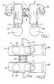
- FIG. 1 and 2 of the drawings there is shown a reservoir, indicated generally by the reference 1, mounted in working relationship on a pair of pressure cylinders 2, 3 forming part, for example, of a tractor hydraulic braking system and being conveniently of the centre valve type, as is generally conventional in such systems.
- Each cylinder has a flange 2B, 3B for use in mounting the cylinder in its position of use, such as on a vehicle bulkhead, for example.
- the reservoir includes a pair of compartments 4, 5 each having a spigot 6, 7 for forming a fluid-tight connection with a boss 2A, 3A of one of the pressure-cylinders.
- Each boss would normally have a cylindrical insert of rubber or plastics material (not shown) inserted in a bore thereof to receive one of the reservoir spigots in fluid-tight engagement.
- the compartments are provided with respective fluid connections 4A, 4B for connection to the tractor hydraulic system so that a continuous flow of fluid through the compartments is maintained during operation of the tractor, in conventional manner.
- a flexible connector means shown as a convoluted tube or bellows 8.
- the reservoir comprising the compartments 4 and 5, spigots 6, 7, connections 4A, 4B and the connector means 8 may advantageously be formed as a single piece by a blow moulding process and can thus be produced inexpensively.
- the convoluted connector means 8 permits a considerable degree of departure of the compartments in all directions from the positions shown in Figures 1 and 2, thereby providing considerable latitude in the relative positions of the pressure cylinders when mounted in their positions of use.
- Such possible variables as the centres of the bores receiving the spigots 6, 7, the centres of holes in the cylinder fixing flanges 2B, 3B, and discrepancies in the mounting bulkhead of the tractor can be accommodated by the reservoir assembly, even when made as a one- piece item in the manner described.
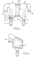
- FIG. 3 and 4 The embodiment shown in Figures 3 and 4 is generally similar to that previously described, having reservoir compartments 4, 5, interconnected by a convolute connector means 8.
- the compartments are provided with mounting spigots 6, 7 and fluid flow connections, as before.
- One principal difference in this embodiment is in the size and cross-sectional shape of the connector means 8 which, as can be seen from Figure 4, generally follows the outline shape of the sides of the compartments and is nearly co-extensive in area with said sides.
- the reservoir of this embodiment may again advantageously be integrally formed by a blow moulding process.
- each tube 10 is provided with a radial flange 12 formed by a separate component which is secured to the tube by a crimping operation.
- An axially extending part 13 of the flange has a serrated outer surface and such serrations may conveniently be formed during the crimping operation which secures the flange member to the tube 10. It would, of course, be possible to secure the flange 12 in position on the tube by alternative means such as welding or soldering, or to form it integrally with the tube, in which case the serrations would be pre-formed in a separate step.
- the connectors 6 and 7 are secured to the compartment 2 during the moulding operation which forms the reservoir 1.
- the assembly of tube 10 and its attached flange 12 is held firmly, by an appropriate jig or other support, in a position such that the flowable material being moulded to form the reservoir 1 can pass around the flange 12 to either side thereof so that the material comes into contact not only with opposed surfaces of the flange, but at one side of the flange with the cylindrical outer surface of the tube 10 and at the opposite side of the flange with an outwardly flared portion' 14 of the tube.
- the connector 7 will be rigidly held within the material of the reservoir, being precluded from axial withdrawal by the flange 12 and from rotation by the serrated portion 13. An excellent fluid tight integrity is obtained between the reservoir and connection 7 being attributable partly to the intimate contact between the material of the reservoir and the outwardly flared portion 14 of the connector.
- the plug insert 11 may either be present on the tube 10, being retained thereon by a further outwardly flared end portion 14 of the tube, to form a sub-assembly before the moulding operation; alternatively, the plug insert may be added after the moulding operation, the provision of the flared portion 14 then being deferred until such time as the insert 11 has been placed around the tube 10.
- the connectors 6, 7 are identical, only one has been illustrated in detail but it will be understood that both are secured to the reservoir by the method described above. This provides a very simple and convenient manner of securing a rigid tube 10 to a reservoir in order to form an outlet connection and is not subject to the complexity of many prior art arrangements.
- This type of connector and its manner of fixing may be applied to any embodiment of the invention, including those described herein. It will be understood that the precise nature of the insert 11 and the shape and arrangement of the flange 12 may be varied according to requirements.
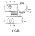
- Figure 5 shows an embodiment of the reservoir assembly suitable for use with a braking system having a self-contained fluid supply, as distinct from the continuous fluid flow type of system with which the previously described embodiments are adapted for use.
- the flow connections 4A, 5A are dispensed with and one of the reservoir compartments, 4, 5, is provided with a fluid filler orifice closed by a cap 10 threadedly engaged with a neck 11 surrounding the filler orifice. Fluid can pass freely between the compartments 4, 5, and through the connector means 8, as before, according to the fluid demands made by the cylinders, and any fall in fluid level in the compartments may be made good by addition of fluid through the filler orifice.
- the reservoir of the invention is not only capable of being inexpensively manufactured from plastics material by a simple blow moulding process, but it enables the various discrepancies referred to herein, arising from manufacturing tolerances, to be readily accommodated simply by flexure of the connector means 8.
Landscapes
- Engineering & Computer Science (AREA)
- Transportation (AREA)
- Mechanical Engineering (AREA)
- Transmission Of Braking Force In Braking Systems (AREA)
Claims (10)
Applications Claiming Priority (4)
| Application Number | Priority Date | Filing Date | Title |
|---|---|---|---|
| GB8405163 | 1984-02-28 | ||
| GB848405163A GB8405163D0 (en) | 1984-02-28 | 1984-02-28 | Master cylinder reservoir |
| GB8418625 | 1984-07-20 | ||
| GB848418625A GB8418625D0 (en) | 1984-07-20 | 1984-07-20 | Master cylinder reservoir |
Publications (2)
| Publication Number | Publication Date |
|---|---|
| EP0156499A1 EP0156499A1 (de) | 1985-10-02 |
| EP0156499B1 true EP0156499B1 (de) | 1988-09-14 |
Family
ID=26287379
Family Applications (1)
| Application Number | Title | Priority Date | Filing Date |
|---|---|---|---|
| EP85301138A Expired EP0156499B1 (de) | 1984-02-28 | 1985-02-20 | Hauptzylindervorratsbehälter |
Country Status (5)
| Country | Link |
|---|---|
| US (1) | US4674282A (de) |
| EP (1) | EP0156499B1 (de) |
| BR (1) | BR8500869A (de) |
| DE (1) | DE3564925D1 (de) |
| GB (1) | GB2154683B (de) |
Cited By (1)
| Publication number | Priority date | Publication date | Assignee | Title |
|---|---|---|---|---|
| DE4221770A1 (de) * | 1992-07-02 | 1994-01-05 | Teves Gmbh Alfred | Bremsflüssigkeitsbehälter |
Families Citing this family (3)
| Publication number | Priority date | Publication date | Assignee | Title |
|---|---|---|---|---|
| GB0008498D0 (en) * | 2000-04-07 | 2000-05-24 | Delphi Tech Inc | Fluid reservoir system for a master cylinder |
| FR2810097B1 (fr) * | 2000-06-09 | 2005-04-08 | Bosch Gmbh Robert | Support pour connecteur rapide, reservoir et systeme d'alimentation en liquide de frein comportant un tel support |
| GB0327402D0 (en) * | 2003-11-25 | 2003-12-31 | Meritor Heavy Vehicle Braking | Twin master cylinder assembly |
Family Cites Families (13)
| Publication number | Priority date | Publication date | Assignee | Title |
|---|---|---|---|---|
| US1930033A (en) * | 1930-06-12 | 1933-10-10 | Bendix Brake Co | Means for automatically supplying fluid brake systems |
| FR1212400A (fr) * | 1958-10-14 | 1960-03-23 | Réservoir en matière plastique et à goulot | |
| US3233411A (en) * | 1963-07-02 | 1966-02-08 | Ford Motor Co | Hydraulic mechanism |
| US3724497A (en) * | 1971-03-04 | 1973-04-03 | Metzeler Ag | Storage system for gaseous fluids and the like |
| JPS50111474A (de) * | 1974-02-14 | 1975-09-02 | ||
| US3914943A (en) * | 1974-06-20 | 1975-10-28 | Bendix Corp | Return manifold for hydraulic brake actuator |
| US3906995A (en) * | 1974-08-14 | 1975-09-23 | Phillips Petroleum Co | Tank cars |
| US4168613A (en) * | 1975-03-15 | 1979-09-25 | Nisshin Kogyo Kabushiki Kaisha | Oil reservoir device with oil level detector means for a tandem type master cylinder |
| JPS5820445Y2 (ja) * | 1977-07-30 | 1983-04-27 | アイシン精機株式会社 | マスタシリンダリザ−バ |
| FR2452406A1 (fr) * | 1979-03-27 | 1980-10-24 | Transformat Mat Plastiques | Reservoir moule a deux cuves pour double circuit |
| DE3045814A1 (de) * | 1980-12-05 | 1982-07-08 | Alfred Teves Gmbh, 6000 Frankfurt | Zweikreis-hauptbremszylinder |
| FR2499010A1 (fr) * | 1981-01-30 | 1982-08-06 | Dba | Systeme de freinage pour vehicule automobile forme d'un tracteur et d'une remorque |
| DE3239438A1 (de) * | 1982-10-25 | 1984-04-26 | Alfred Teves Gmbh, 6000 Frankfurt | Kunststoff-ausgleichsbehaelter fuer hydraulische bremsanlagen |
-
1985
- 1985-02-20 EP EP85301138A patent/EP0156499B1/de not_active Expired
- 1985-02-20 DE DE8585301138T patent/DE3564925D1/de not_active Expired
- 1985-02-20 GB GB08504324A patent/GB2154683B/en not_active Expired
- 1985-02-25 US US06/704,926 patent/US4674282A/en not_active Expired - Fee Related
- 1985-02-27 BR BR8500869A patent/BR8500869A/pt unknown
Cited By (1)
| Publication number | Priority date | Publication date | Assignee | Title |
|---|---|---|---|---|
| DE4221770A1 (de) * | 1992-07-02 | 1994-01-05 | Teves Gmbh Alfred | Bremsflüssigkeitsbehälter |
Also Published As
| Publication number | Publication date |
|---|---|
| DE3564925D1 (en) | 1988-10-20 |
| US4674282A (en) | 1987-06-23 |
| GB8504324D0 (en) | 1985-03-20 |
| GB2154683A (en) | 1985-09-11 |
| EP0156499A1 (de) | 1985-10-02 |
| GB2154683B (en) | 1987-12-02 |
| BR8500869A (pt) | 1985-10-15 |
Similar Documents
| Publication | Publication Date | Title |
|---|---|---|
| US4615098A (en) | Process for forming an hydraulic connection | |
| EP0550742B1 (de) | Bremsbetätigungsbaugruppe für kraftfahrzeuge | |
| EP4001033B1 (de) | Elektrohydraulisches bremssystem | |
| US4674282A (en) | Master cylinder reservoir | |
| US4902032A (en) | Motor vehicle steering | |
| US4772051A (en) | Modular manifold brake hose end fitting | |
| EP0497513B1 (de) | Gelenk für eine Zahnstangenlenkungseinheit | |
| US4566276A (en) | Inlet assembly for a brake master cylinder | |
| US20020117851A1 (en) | Fluid couplings | |
| US4813517A (en) | Modular manifold brake hose end fitting | |
| US6631929B1 (en) | Connection cartridge for air tanks | |
| GB2111152A (en) | Brake booster housing | |
| US4488742A (en) | Connecting arrangement, especially for tubular elements | |
| US4793139A (en) | Joint for two piece plastic master cylinder housing | |
| US7318370B2 (en) | Tie rod for booster and booster comprising such a tie rod | |
| JPS5924031B2 (ja) | 自動二輪車用ブレ−キ作動装置 | |
| JPH0413258Y2 (de) | ||
| GB2158171A (en) | Hose unions | |
| JP4422663B2 (ja) | 車両用液圧マスタシリンダのリザーバ及びその製造方法 | |
| EP0284221A1 (de) | Hauptzylinder | |
| US4502281A (en) | Fluid reservoir | |
| US4038822A (en) | Fastener means for connecting a cylindrical body to a hub means | |
| US6668968B2 (en) | Power steering system | |
| US4875392A (en) | Manual valve in an automatic transmission | |
| EP0129964A1 (de) | Hydraulisches Bremssystem |
Legal Events
| Date | Code | Title | Description |
|---|---|---|---|
| PUAI | Public reference made under article 153(3) epc to a published international application that has entered the european phase |
Free format text: ORIGINAL CODE: 0009012 |
|
| AK | Designated contracting states |
Designated state(s): DE FR IT |
|
| 17P | Request for examination filed |
Effective date: 19860304 |
|
| 17Q | First examination report despatched |
Effective date: 19861008 |
|
| GRAA | (expected) grant |
Free format text: ORIGINAL CODE: 0009210 |
|
| AK | Designated contracting states |
Kind code of ref document: B1 Designated state(s): DE FR IT |
|
| ITF | It: translation for a ep patent filed | ||
| REF | Corresponds to: |
Ref document number: 3564925 Country of ref document: DE Date of ref document: 19881020 |
|
| ET | Fr: translation filed | ||
| PGFP | Annual fee paid to national office [announced via postgrant information from national office to epo] |
Ref country code: FR Payment date: 19890209 Year of fee payment: 5 |
|
| ITTA | It: last paid annual fee | ||
| PGFP | Annual fee paid to national office [announced via postgrant information from national office to epo] |
Ref country code: DE Payment date: 19890323 Year of fee payment: 5 |
|
| PLBE | No opposition filed within time limit |
Free format text: ORIGINAL CODE: 0009261 |
|
| STAA | Information on the status of an ep patent application or granted ep patent |
Free format text: STATUS: NO OPPOSITION FILED WITHIN TIME LIMIT |
|
| 26N | No opposition filed | ||
| PG25 | Lapsed in a contracting state [announced via postgrant information from national office to epo] |
Ref country code: FR Effective date: 19901031 |
|
| PG25 | Lapsed in a contracting state [announced via postgrant information from national office to epo] |
Ref country code: DE Effective date: 19901101 |
|
| REG | Reference to a national code |
Ref country code: FR Ref legal event code: ST |