EP0156531A1 - Einrichtung zum Bilden von ringförmigen Nuten oder Schlitzen in strangförmigen Artikeln - Google Patents
Einrichtung zum Bilden von ringförmigen Nuten oder Schlitzen in strangförmigen Artikeln Download PDFInfo
- Publication number
- EP0156531A1 EP0156531A1 EP85301413A EP85301413A EP0156531A1 EP 0156531 A1 EP0156531 A1 EP 0156531A1 EP 85301413 A EP85301413 A EP 85301413A EP 85301413 A EP85301413 A EP 85301413A EP 0156531 A1 EP0156531 A1 EP 0156531A1
- Authority
- EP
- European Patent Office
- Prior art keywords
- channel
- article
- belt
- rod
- former
- Prior art date
- Legal status (The legal status is an assumption and is not a legal conclusion. Google has not performed a legal analysis and makes no representation as to the accuracy of the status listed.)
- Granted
Links
Images
Classifications
-
- A—HUMAN NECESSITIES
- A24—TOBACCO; CIGARS; CIGARETTES; SIMULATED SMOKING DEVICES; SMOKERS' REQUISITES
- A24D—CIGARS; CIGARETTES; TOBACCO SMOKE FILTERS; MOUTHPIECES OF CIGARS OR CIGARETTES; MANUFACTURE OF TOBACCO SMOKE FILTERS OR MOUTHPIECES
- A24D3/00—Tobacco smoke filters, e.g. filter tips or filtering inserts; Filters specially adapted for simulated smoking devices; Mouthpieces of cigars or cigarettes
- A24D3/02—Manufacture of tobacco smoke filters
- A24D3/025—Final operations, i.e. after the filter rod forming process
- A24D3/0258—Means for making grooves
Definitions
- the present invention pertains generally to apparatus for forming annular slits or grooves in rod-shaped articles such as cigarette filter plugs, and pertains more specifically to such apparatus of a type adjustable to control the depth of the slit or groove and to accommodate rod-shaped articles of different diameters.
- Annular grooves are conventionally provided in filter plugs and similar objects for various purposes.
- annular grooves in a smoke-impermeable filter plug for admitting air into the filter interior to dilute the smoke stream are known.
- Certain gas-phase components of cigarette smoke are also known to be adsorbable on properly treated walls of annular or other grooves formed in the outer surface of a filter plug.
- a smoke-impermeable, generally annular groove provided in the filter plug can also be used to produced a venturi flow of the smoke stream toward the smoker's mouth.
- the groove is cut-in a filter plug by means of_a rotating knife of one kind or another, frequently a rotating disc knife.
- the knife can be heated if it is desired to heat-seal the groove surface.
- grooves can be formed during extrusion of the filter plugs by means of periodic constriction of the extrusion die, as disclosed in US-A-3 648 711.
- the filter plug is held during the cutting operation in a groove or flute on the periphery of a rotating drum, to which the filter plug is held by means of vaccum suction.
- a heated forming element can be used instead of a knife, as for example in US-A-4 149 546.
- Another object of the invention is to provide such an apparatus in which the feed rate of the machine can be controlled independently of the rolling speed of the articles therein.
- Another object of the invention is to provide such an apparatus capable of accommodating rod-shaped articles of different diameters.
- Still another object of the invention is to provide such an apparatus adapted for forming such a slit of substantially uniform depth.
- the apparatus of the invention comprises a first endless belt or similar device and, spaced apart therefrom, a second element defining, with the belt, a channel of a predetermined width.
- the size of the channel can preferably be adjusted by moving the belt, the second element or both toward or away from each other, to accommodate articles of different sizes.
- the apparatus also includes a mechanism for driving the belt to enable it, in cooperation with the second element, to transport a rod-shaped article gripped between them from one end of the channel to the other.
- the apparatus of the invention further comprises a forming device, which is most preferably a rotating disc knife, having a portion disposed in the channel to cut any article along the channel moved from one end to the other.
- a rod-shaped article such as a filter plug is rolled along the channel. If the rate of rotation of the article is sufficiently large compared to the linear speed of the article along the channel, the article is rotated at least once about its own axis while within range of the former. This results in the former producing a complete annular groove or slit in the article.
- the surface of the second element, adjacent the former is made parallel to and spaced a constant distance from the operative surface or edge of the former (hereinafter the "forming profile"), so that the depth of the cut or groove is uniform.
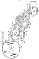
- the figure is an elevational view of the preferred embodiment of the apparatus of the invention.
- the figure shows in elevation a first preferred embodiment of the apparatus of the invention.
- the embodiment shown includes a conventional hopper 12 in which cigarette filter rods or other rod-shaped articles are received with their longitudinal axes horizontal and parallel.
- the bottom of the hopper 12 is located immediately above a drum 14 mounted for rotation about a horizontal axis 16.
- the periphery of drum 14 is piovided with flutes 18 equally spaced about its circumference and oriented to receive filter plugs F from hopper 12.
- a refuser roller 20 is located at one end of the bottom of the hopper 12 and rotates in the same sense (clockwise in the device shown) as does drum 14 to prevent the accidental escape of filter rods from hopper 12, in a known manner.
- a transfer drum 22 Adjacent to drum 14 is a transfer drum 22 mounted for rotation about an axis 24 parallel to axis 16.
- the transfer drum 22 also has peripheral flutes 26 for receiving filter plugs from drum 14.
- the two drums 14, 22 are located and are operated in a known manner such that filter plugs F are passed from drum 14 to drum 22.
- a preferably horizontal passageway or channel 28 defined between upper and lower belts 30, 32, for carrying the filter plugs away from the transfer drum 22.
- the lower belt 32 is mounted for rotation on two drums 34, 36 disposed below and to each side of the transfer drum 22.
- a plate 38 is disposed just below the upper trace of the lower belt 32 to aid in supporting the filter plugs F as they are released by the transfer drum 22.
- a tensioning device 40 is disposed below the lower belt 32 to control the belt tension in a known manner.
- the upperside of the channel 28 is defined in the embodiment shown by belt 30, which is carried by transfer drum 22 and an additional drum 42 downstream of the transfer drum 22 and of the drums 34, 36 supporting the lower belt 32.
- the upper belt 30, which is received in a groove or a set of grooves formed in the circumference of the transfer drum 22, is also wrapped around two pulleys 44, 46 of a second_ conventional tensioning device 48, as shown.
- the - upper belt 30 is tensioned by tensioning device 48 in a known manner.
- a guide plate 50 is deposed just above the lower trace of the upper belt 30 to cooperate with the lower guide plate 38 in controlling the movement of the filter rods F in the channel 28.
- the vertical spacing between the two horizontal guide plates 38, 50 can, if desired, be made adjustable by suitable conventional means.
- the actual movement of filter rods F along the channel 28, however, is caused by the movement of the belts 30, 32.
- the belts 30, 32 are driven in opposite senses at such a speed as to cause the filter rods F released by the transfer drum 22 to move horizontally away from the transfer drum 22 without rotation.
- a third belt conveyor 52 whose upper trace is co-plannar with that of the first lower belt 32, is disposed downstream of the latter and beneath the downstream portion of the upper belt 30.
- the third belt conveyor 52 is mounted on drums 36, 54, 56 and also passes around one pulley 58 of a tensioning device 60 and follows a path which is approximately a parallelogram, with the upper side of the parallelogram being horizontal.
- the upper downstream drum 54 carrying the third belt 52 is an idler drum on which a disc knife 62 is concentrically mounted and driven for rotation about the axis of drum 54.
- An additional guide plate 64 is disposed between the two upper drums 36, 54 supporting the third belt conveyor 52 and cooperates with the upper guide plate 50 to control the filter rods F, especially as the latter pass the downstream limit of the upper belt 30.
- a rolling block 66 mounted on the machine either fixably or in such a manner that the spacing of the rolling block 66 from drum 59 can be adjusted.
- the undersurface 68 of the rolling block 66 is curved to parallel the third belt conveyor 52 as the latter passes over the idler drum 54 from the upper, horizontal trace of the conveyor 52 toward drum 56.
- the upper belt 30 and the third belt 52 are driven so that their opposing traces move in the same direction but at different speeds.
- a filter rod F between them rotates about its longitudinal axis, preferably in the direction indicated by arrows A in the figure.
- the filter plug F moves downstream from the upper belt 30, it is rolled by the third belt 52 against the upper guide plate 50.
- the third belt 52 continues rolling the filter plug F, along the lower surface 68 of the rolling block 66.
- the slitter knife 62 borne on the idler drum 54 extends somewhat above the third belt 52 and into the channel 28, and the surface 68 of the rolling block 66 is a uniform distance from the knife edge. (If a former other than a knife is used, the rolling block surface will be parallel to the contour of the operative edge, or profile, of the former.) As the filter plugs F are rolled along the rolling block surface 68, they are cut by the knife 62 to form an annular groove. Because the filter plugs F are moved along and parallel to the periphery of the circular knife 62, rather than simply being moved in a linear path past the knife 62, the grooves are of uniform depth and are concentric with the filter rod axis.
- the filter plugs F slide down the third belt 52 and a guide plate 70 at the lower end of the third belt conveyor 52 onto the upper surface of a take-away conveyor 72 supported on drums 74 (only one of which is shown), for transport to the next work station.
- the position of the roller block 66 relative to belt 52 and the knife 62 can preferably be adjusted, the depth of the grooves produced in the filter plugs can be varied at will, and a complete severing of the filter plugs can even be achieved using the apparatus of the invention by moving the rolling block 66 close enough to drum 54. Also, control of the linear speeds of the lower belts 32, 52 independently of that of the upper belt 30 permits the speed of the filter plug along the channel 28 to be controlled independently of the rotational speed of the filter plug F.
Landscapes
- Manufacturing Of Cigar And Cigarette Tobacco (AREA)
- Cigarettes, Filters, And Manufacturing Of Filters (AREA)
Applications Claiming Priority (2)
| Application Number | Priority Date | Filing Date | Title |
|---|---|---|---|
| US06/585,167 US4795411A (en) | 1984-03-01 | 1984-03-01 | Apparatus for forming annular grooves or slits in rod-shaped articles |
| US585167 | 1984-03-01 |
Publications (2)
| Publication Number | Publication Date |
|---|---|
| EP0156531A1 true EP0156531A1 (de) | 1985-10-02 |
| EP0156531B1 EP0156531B1 (de) | 1989-02-15 |
Family
ID=24340302
Family Applications (1)
| Application Number | Title | Priority Date | Filing Date |
|---|---|---|---|
| EP85301413A Expired EP0156531B1 (de) | 1984-03-01 | 1985-03-01 | Einrichtung zum Bilden von ringförmigen Nuten oder Schlitzen in strangförmigen Artikeln |
Country Status (3)
| Country | Link |
|---|---|
| US (1) | US4795411A (de) |
| EP (1) | EP0156531B1 (de) |
| DE (1) | DE3568252D1 (de) |
Cited By (3)
| Publication number | Priority date | Publication date | Assignee | Title |
|---|---|---|---|---|
| AU707625B2 (en) * | 1996-03-20 | 1999-07-15 | Aver Plastic Industrial Corp. | A channeling machine |
| GB2521167A (en) * | 2013-12-11 | 2015-06-17 | British American Tobacco Co | An apparatus for forming a circumferential slit in a tobacco industry rod article |
| DE102014210102A1 (de) | 2014-05-27 | 2015-12-03 | Hauni Maschinenbau Ag | Schneiden von stabförmigen Artikeln der Tabak verarbeitenden Industrie |
Families Citing this family (2)
| Publication number | Priority date | Publication date | Assignee | Title |
|---|---|---|---|---|
| US5692526A (en) * | 1992-09-11 | 1997-12-02 | Philip Morris Incorporated | Cigarette for electrical smoking system |
| DE102006001445A1 (de) * | 2006-01-10 | 2007-07-19 | Hauni Maschinenbau Ag | Fördern von stabförmigen Artikeln der Tabak verarbeitenden Industrie |
Citations (3)
| Publication number | Priority date | Publication date | Assignee | Title |
|---|---|---|---|---|
| US4232574A (en) * | 1977-08-19 | 1980-11-11 | Liggett Group Inc. | Apparatus and method for providing a cigarette filter with an aeration groove |
| EP0076641A1 (de) * | 1981-09-30 | 1983-04-13 | Philip Morris Incorporated | Verfahren und Vorrichtung für die Herstellung von Rauchfilterbestandteilen |
| US4385536A (en) * | 1980-03-28 | 1983-05-31 | Liggett Group Inc. | Apparatus for forming an aeration groove in a filter |
Family Cites Families (7)
| Publication number | Priority date | Publication date | Assignee | Title |
|---|---|---|---|---|
| US3648711A (en) * | 1970-08-11 | 1972-03-14 | American Filtrona Corp | Tobacco smoke filter |
| GB1507765A (en) * | 1976-03-17 | 1978-04-19 | British American Tobacco Co | Production of tobacco-smoke filters |
| US4369796A (en) * | 1977-08-19 | 1983-01-25 | Liggett Group Inc. | Method and apparatus for forming an air dilution filter |
| US4219030A (en) * | 1977-08-19 | 1980-08-26 | Liggett Group Inc. | Aeration groove filter |
| GB2078089B (en) * | 1980-06-18 | 1983-10-12 | British American Tobacco Co | Filters and a method of producing such filters |
| US4324540A (en) * | 1980-07-11 | 1982-04-13 | Brown & Williamson Tobacco Corporation | Apparatus for making grooves in tobacco smoke filters |
| US4351792A (en) * | 1980-07-11 | 1982-09-28 | Brown & Williamson Tobacco Corporation | Apparatus for making grooves in tobacco smoke filters |
-
1984
- 1984-03-01 US US06/585,167 patent/US4795411A/en not_active Expired - Lifetime
-
1985
- 1985-03-01 DE DE8585301413T patent/DE3568252D1/de not_active Expired
- 1985-03-01 EP EP85301413A patent/EP0156531B1/de not_active Expired
Patent Citations (3)
| Publication number | Priority date | Publication date | Assignee | Title |
|---|---|---|---|---|
| US4232574A (en) * | 1977-08-19 | 1980-11-11 | Liggett Group Inc. | Apparatus and method for providing a cigarette filter with an aeration groove |
| US4385536A (en) * | 1980-03-28 | 1983-05-31 | Liggett Group Inc. | Apparatus for forming an aeration groove in a filter |
| EP0076641A1 (de) * | 1981-09-30 | 1983-04-13 | Philip Morris Incorporated | Verfahren und Vorrichtung für die Herstellung von Rauchfilterbestandteilen |
Cited By (5)
| Publication number | Priority date | Publication date | Assignee | Title |
|---|---|---|---|---|
| AU707625B2 (en) * | 1996-03-20 | 1999-07-15 | Aver Plastic Industrial Corp. | A channeling machine |
| GB2521167A (en) * | 2013-12-11 | 2015-06-17 | British American Tobacco Co | An apparatus for forming a circumferential slit in a tobacco industry rod article |
| WO2015086314A1 (en) * | 2013-12-11 | 2015-06-18 | British American Tobacco (Investments) Limited | An apparatus for forming a circumferential slit in a tobacco industry rod article |
| US10292420B2 (en) | 2013-12-11 | 2019-05-21 | British American Tobacco (Investments) Limited | Apparatus for forming a circumferential slit in a tobacco industry rod article |
| DE102014210102A1 (de) | 2014-05-27 | 2015-12-03 | Hauni Maschinenbau Ag | Schneiden von stabförmigen Artikeln der Tabak verarbeitenden Industrie |
Also Published As
| Publication number | Publication date |
|---|---|
| DE3568252D1 (en) | 1989-03-23 |
| US4795411A (en) | 1989-01-03 |
| EP0156531B1 (de) | 1989-02-15 |
Similar Documents
| Publication | Publication Date | Title |
|---|---|---|
| SU1762737A3 (ru) | Устройство дл изготовлени рогаликов из скатанного теста | |
| KR0146920B1 (ko) | 화장지등의 작은 로울의 형성을 위해 절단기와 결합된 트림제거장치 | |
| US4830180A (en) | Article inspection and stabilizing system | |
| JPS649131A (en) | Band stretcher with floating type mandrel | |
| US5623952A (en) | Method and apparatus for making filter cigarettes | |
| US4200016A (en) | Apparatus for forming a horizontal stack of vertically oriented sheets | |
| US3828658A (en) | Method and apparatus for producing cigarette filter sleeves | |
| US4802664A (en) | Arrangement for the feeding of sheets to a magazine | |
| US4795411A (en) | Apparatus for forming annular grooves or slits in rod-shaped articles | |
| US3045939A (en) | Flexible material winder | |
| US4861324A (en) | Apparatus for manufacturing tobacco filter | |
| US4982637A (en) | Rotary cutting apparatus | |
| US3728921A (en) | Apparatus for cutting a web into sheets and positioning the sheets | |
| JPS5854047B2 (ja) | 長手方向に配列した個々の製品を包装機械に連続的に供給する装置 | |
| US3721375A (en) | Web feed mechanism for wrapping machines | |
| US5050724A (en) | Roll infeed conveyor | |
| EP0124289B1 (de) | Verfahren und Einrichtung zur Befestigung von Filterspitzen an Rauchartikeln | |
| US3245514A (en) | Device and method for turning around cigarettes and like articles | |
| US4913013A (en) | Rotary cutting apparatus | |
| JP3273803B2 (ja) | シガレット製造機における巻たばこの印刷濃度調整装置 | |
| US3880031A (en) | Machine for manufacturing tinsel | |
| JPH0657136B2 (ja) | 紙巻きたばこ巻き上げ機用帯紙案内装置 | |
| US5359833A (en) | Method of depositing extruded pieces of substances onto individual wrapping sheets and apparatus for carrying out the method | |
| JPS63265886A (ja) | 棒状無煙火薬の連続切断装置 | |
| US1430089A (en) | Web feeding and cutting device |
Legal Events
| Date | Code | Title | Description |
|---|---|---|---|
| PUAI | Public reference made under article 153(3) epc to a published international application that has entered the european phase |
Free format text: ORIGINAL CODE: 0009012 |
|
| AK | Designated contracting states |
Designated state(s): DE GB IT |
|
| 17P | Request for examination filed |
Effective date: 19860325 |
|
| 17Q | First examination report despatched |
Effective date: 19870709 |
|
| RAP1 | Party data changed (applicant data changed or rights of an application transferred) |
Owner name: PHILIP MORRIS PRODUCTS INC. |
|
| GRAA | (expected) grant |
Free format text: ORIGINAL CODE: 0009210 |
|
| AK | Designated contracting states |
Kind code of ref document: B1 Designated state(s): DE GB IT |
|
| ITF | It: translation for a ep patent filed | ||
| REF | Corresponds to: |
Ref document number: 3568252 Country of ref document: DE Date of ref document: 19890323 |
|
| PLBE | No opposition filed within time limit |
Free format text: ORIGINAL CODE: 0009261 |
|
| STAA | Information on the status of an ep patent application or granted ep patent |
Free format text: STATUS: NO OPPOSITION FILED WITHIN TIME LIMIT |
|
| 26N | No opposition filed | ||
| PGFP | Annual fee paid to national office [announced via postgrant information from national office to epo] |
Ref country code: GB Payment date: 19930217 Year of fee payment: 9 |
|
| PGFP | Annual fee paid to national office [announced via postgrant information from national office to epo] |
Ref country code: DE Payment date: 19930222 Year of fee payment: 9 |
|
| ITTA | It: last paid annual fee | ||
| PG25 | Lapsed in a contracting state [announced via postgrant information from national office to epo] |
Ref country code: GB Effective date: 19940301 |
|
| GBPC | Gb: european patent ceased through non-payment of renewal fee |
Effective date: 19940301 |
|
| PG25 | Lapsed in a contracting state [announced via postgrant information from national office to epo] |
Ref country code: DE Effective date: 19941201 |