EP0156693A1 - Schutzeinrichtung gegen elektrische Störungen zwischen einem Terminal und einer Telefonleitung - Google Patents
Schutzeinrichtung gegen elektrische Störungen zwischen einem Terminal und einer Telefonleitung Download PDFInfo
- Publication number
- EP0156693A1 EP0156693A1 EP85400359A EP85400359A EP0156693A1 EP 0156693 A1 EP0156693 A1 EP 0156693A1 EP 85400359 A EP85400359 A EP 85400359A EP 85400359 A EP85400359 A EP 85400359A EP 0156693 A1 EP0156693 A1 EP 0156693A1
- Authority
- EP
- European Patent Office
- Prior art keywords
- terminal
- interface
- telephone line
- transmission
- line
- Prior art date
- Legal status (The legal status is an assumption and is not a legal conclusion. Google has not performed a legal analysis and makes no representation as to the accuracy of the status listed.)
- Ceased
Links
- 230000001681 protective effect Effects 0.000 title description 3
- 230000003287 optical effect Effects 0.000 claims abstract description 39
- 238000002955 isolation Methods 0.000 claims abstract description 15
- 230000005540 biological transmission Effects 0.000 claims description 50
- 239000011810 insulating material Substances 0.000 claims description 4
- 239000013307 optical fiber Substances 0.000 claims description 3
- 230000002457 bidirectional effect Effects 0.000 abstract description 3
- 238000012986 modification Methods 0.000 abstract description 2
- 230000004048 modification Effects 0.000 abstract description 2
- 238000004804 winding Methods 0.000 description 16
- 108091008695 photoreceptors Proteins 0.000 description 12
- 238000004891 communication Methods 0.000 description 6
- 238000010292 electrical insulation Methods 0.000 description 4
- 239000002184 metal Substances 0.000 description 4
- 230000015556 catabolic process Effects 0.000 description 2
- 238000010586 diagram Methods 0.000 description 2
- 238000009434 installation Methods 0.000 description 2
- 230000005693 optoelectronics Effects 0.000 description 2
- 230000000737 periodic effect Effects 0.000 description 2
- 230000005855 radiation Effects 0.000 description 2
- 238000005070 sampling Methods 0.000 description 2
- 206010068150 Acoustic shock Diseases 0.000 description 1
- 238000006677 Appel reaction Methods 0.000 description 1
- 230000004913 activation Effects 0.000 description 1
- 230000006978 adaptation Effects 0.000 description 1
- 239000003990 capacitor Substances 0.000 description 1
- 230000006866 deterioration Effects 0.000 description 1
- 238000006073 displacement reaction Methods 0.000 description 1
- 238000005265 energy consumption Methods 0.000 description 1
- 230000005669 field effect Effects 0.000 description 1
- 238000009413 insulation Methods 0.000 description 1
- 238000004519 manufacturing process Methods 0.000 description 1
- 238000012544 monitoring process Methods 0.000 description 1
- 238000011084 recovery Methods 0.000 description 1
- 230000000630 rising effect Effects 0.000 description 1
- 230000011664 signaling Effects 0.000 description 1
- 230000001360 synchronised effect Effects 0.000 description 1
- 238000012360 testing method Methods 0.000 description 1
- 238000013519 translation Methods 0.000 description 1
Images


Classifications
-
- H—ELECTRICITY
- H02—GENERATION; CONVERSION OR DISTRIBUTION OF ELECTRIC POWER
- H02H—EMERGENCY PROTECTIVE CIRCUIT ARRANGEMENTS
- H02H9/00—Emergency protective circuit arrangements for limiting excess current or voltage without disconnection
- H02H9/04—Emergency protective circuit arrangements for limiting excess current or voltage without disconnection responsive to excess voltage
-
- H—ELECTRICITY
- H04—ELECTRIC COMMUNICATION TECHNIQUE
- H04B—TRANSMISSION
- H04B10/00—Transmission systems employing electromagnetic waves other than radio-waves, e.g. infrared, visible or ultraviolet light, or employing corpuscular radiation, e.g. quantum communication
- H04B10/25—Arrangements specific to fibre transmission
- H04B10/2589—Bidirectional transmission
-
- H—ELECTRICITY
- H04—ELECTRIC COMMUNICATION TECHNIQUE
- H04B—TRANSMISSION
- H04B10/00—Transmission systems employing electromagnetic waves other than radio-waves, e.g. infrared, visible or ultraviolet light, or employing corpuscular radiation, e.g. quantum communication
- H04B10/80—Optical aspects relating to the use of optical transmission for specific applications, not provided for in groups H04B10/03 - H04B10/70, e.g. optical power feeding or optical transmission through water
- H04B10/806—Arrangements for feeding power
- H04B10/808—Electrical power feeding of an optical transmission system
Definitions
- the present invention relates generally to the protection of users of telephone and / or telematic terminals against overvoltages transmitted by telephone lines, caused by lightning in particular.
- a user is connected to a telephone line serving a terminal by means of a handset or a keyboard included in the terminal.
- a means of protection including surge arresters connected to earth is provided at the junction of the terminal and the telephone line.
- an overvoltage created in the telephone line by electrical disturbances, such as lightning or contact with an electric line is transmitted to the user by a terminal member, handset or keyboard, manipulated by the user.
- This overvoltage causes serious disturbances in the user, due for example to acoustic shocks produced by the shaking of the handset.
- a large current can pass through the body of the user and result, at worst, in the lightning strike of the user.
- a so-called wireless telephone set isolates the user and the handset from the telephone line only during communication after the off-hook phase and before the on-hook phase.
- This isolation is provided by the bidirectional link, generally with infrared radiation, between a first interface included in the mobile handset and a second interface included in a fixed module and connected to the telephone line.
- the second interface draws its supply energy from the electrical sector through a transformer, in order to supply sufficient energy to supply means for transmitting and receiving optical signals in the second interface.
- the user is in contact with the fixed module, connected both to the telephone line and to the mains through the transformer.
- the risks of transmitting energy from electrical disturbances to the user are therefore increased compared to those presented by a conventional telephone set perfectly isolated from the sector and drawing its energy from the remote supply current of the telephone line.
- the infrared link is planned for a long distance, of the order of several meters.
- the infrared link requires in the two interfaces means for transmitting and receiving optical signals using very complex modulations and demodulations in order to minimize the influence of optical disturbances in the infrared link.
- the object of the present invention is to provide a device for protection against electrical disturbances interconnected between a terminal and a telephone line which at all times ensures very high voltage electrical insulation between the terminal in contact with the user and the telephone line , without any additional modification of the terminal.
- a protection device comprising a first interface connected to the terminal and a second interface connected to the telephone line, the first and second interfaces comprising first transmission means for converting first electrical signals transmitted by the terminal into first optical signals and first reception means for converting the first optical signals into lo0 first electrical signals to be transmitted to the telephone line, and the second and first interfaces comprising second transmission means for converting second electrical signals transmitted by the telephone line into second optical signals and second reception means for converting the second optical signals into the second electrical signals to be transmitted to the terminal, is characterized in that it comprises first and second electrical isolation means to guide the first and second optical signals and in that the first interface comprises first means for supplying current from the mains to said terminal, the first transmission means and the second reception means, and the second interface comprises second means for supplying current from the remote supply current of the telephone line the first means of reception and the second transmission means.
- the first interface and the terminal are supplied by the sector and the second interface is supplied by the remote supply current in the telephone line, which ensures perfect isolation between the sector at the terminal of the user and the telephone line through the means for guiding the optical signals.
- the means for guiding the optical signals are in the form of tubes of insulating material with opaque walls or of optical fibers extending between housings containing the interfaces.
- the optical signals are then protected against any external optical disturbance.
- the transmission means can directly apply,. Without any intermediate modulation, the electrical signals in baseband to photoemitters.
- the cost of the protection device according to the invention is thus lower than that for a wireless telephone set with infrared link.
- the means for guiding the optical signals have a length of a few tens of centimeters in order to ensure electrical insulation at least greater than 300 kV between the two interfaces.
- the short length of the means for guiding thus requires only a low optical power of radiation from the emission means.
- the remote supply current in the telephone line of the order of 30 mA, is sufficient to supply the transmission and reception means in the second interface.
- the transmission and reception means in both the first and second interfaces are only supplied during the periods of operation of the terminal in order to reduce the energy consumption of the protection device.
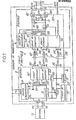
- the protection device 1 is a quadrupole interconnected between two terminals of a terminal TL and the ends of two wires T and R of a telephone line.
- the TL terminal can be a subscriber telephone installation having one or more telephone sets, or a simple telephone set.
- the terminal TL can be a telephone and telematic subscriber installation serving by a common bus one or more telephone sets and one or more known telematic terminals with keyboard and screen.
- the telephone line TR can be a subscriber connection line attached to a telephone and / or telematics exchange.
- the telephone line can be a specialized telephone line or not at a telephone exchange and the terminal can be monitoring equipment such as a measuring device, for example for testing transmission faults in the line.
- the protection device 1 comprises an optoelectronic electrical isolation circuit 2 with separate channels for the two directions of transmission, and on either side of the circuit 2, a first interface 3 on the side of the terminal TL and a second interface 4 on the side of the TR telephone line.
- the two interfaces 3 and 4 include hybrid couplers, for example in the form of differential transformers 30 and 40, for adapting bidirectional two-wire transmissions at the TL terminal and at the TR line to a 2T transmission channel and to a 2R receive channel in circuit 2.
- a primary winding 300 of the transformer 30 is interconnected between a negative terminal 31 of a power source 31 and a coil terminal 32 of a first relay.
- the other positive terminal 31 + of the source 31 and another terminal of the coil 32 are connected to the terminals of the terminal TL through the terminals BI and B2 and the contactor CTL respectively.
- the power source 31 is conventional and has two input terminals S connected to the sector. It supplies the loop current necessary for the operation of the TL terminal and of the first interface 3.
- the source 31 includes a backup battery to supply the TL terminal in the event of a power failure.
- First electrical speech and multi-frequency signals transmitted by the terminal TL are taken by a first secondary winding 30T of the differential transformer 30 forming an input of a first transmission medium of the transmission path 2T.
- the first transmission support comprises in the isolation circuit 2, a photoemitter 23T connected to the winding 30T through a transmission circuit 36T, a photoreceptor 24T and an optical guide 22T.
- the emission circuit 36T and the photoemitter 23T constitute first emission means for converting the first electrical signals into first optical signals.
- the guide 22T conveys the first optical signals emitted by the photoemitter 23T to the photoreceptor 24T corresponding to the first electrical speech and multifrequency signals transmitted by the terminal TL.
- the output of the first transmission medium is constituted by a first secondary winding 40T of the differential transformer 40 in the second interface 4, connected to the photoreceptor 24T through a reception circuit 46T.
- the photoreceptor 24T and the reception circuit 46T constitute first reception means for converting the first optical signals into the first electrical signals.
- the speech and multifrequency signals transmitted by the terminal TL are then conveyed to the line TR through a primary winding 400 of the transformer 40.
- the wire T is connected to a terminal of the winding 400 through a movable contact and a first stationary contact of a first switch 42T.
- the wire R is connected to the other terminal of the winding 400 through a movable contact and a first stationary contact of a second switch 42R and through a protective resistor 43.
- a double Zener diode 45 is interconnected at the terminals of the primary winding 400.
- the elements 43 and 45 constitute means of protection of the circuits of the interface 4, intended for the clipping of possible overvoltages.
- Second electrical and multifrequency speech signals transmitted by the telephone line TR to the terminal TL take the reception channel 2R which is composed in a manner analogous to the first transmission medium.
- the input and output of the reception channel 2R are formed by second secondary windings 40R and 30R of the differential transformers 30 and 40.
- the reception channel 2R comprises a photoemitter 24R connected to the winding 40R through a circuit of transmission 46R, a photoreceptor 23R connected to the winding 30R through a reception circuit 36R, and an optical guide 22R.
- the guide 22R conveys second optical signals emitted by the photoemitter 24R to the photoreceptor 23R, corresponding to the speech and multifrequency signals transmitted by the line TR.
- the photoemitters such as the 23T and 24R photoemitters, are for example light emitting diodes such as light emitting diodes (LEDs) emitting in the near infrared with a wavelength of the order of 950 nm .
- the diodes are polarized by a direct current modulated by baseband signals corresponding to the speech and multifrequency signals and operate in linear mode. These conditions are ensured by known amplifiers constituting the transmission circuits 36T and 46R.
- the reception circuits 46T and 36R are constituted by known amplifiers.
- the optical guides 22T and 22R have a length which depends on the electrical insulation which it is desired to obtain.
- the galvanic isolation thus obtained between the two interfaces 3 and 4, that is to say between the terminal TL and the line TR, is greater than that conferred by known optoelectronic photocouplers.
- the length of the optical guides 22R and 22T is approximately equal to 30 cm for a desired electrical insulation of voltage at 900 kV.
- a bias current of the diodes 23T and 24R of the order of 5 mA is sufficient.
- the optical guides 22T and 22R are constituted by tubes of insulating material with opaque walls having ends fixed to support bases containing the photoemitters and photoreceptors, as shown diagrammatically in FIG. 2.
- the optical guides 22T and 22R are constituted by optical fibers, the ends of which are positioned opposite the photoemitters and photoreceptors in known packages.
- the photoreceptors 24T and 23R are for example photosensitive junction elements such as phototransistors or photodiodes.
- interfaces 3 and 4 are housed in small boxes B3 and B4 fixed to the bottom of an insulating box BO.
- the guides 22T and 22R extend parallel between the boxes B3 and B4.
- the circuits in the second interface 4, such as the transmission circuits 46R and reception 46T, are supplied by a supply circuit 41 which takes the necessary supply energy from the remote supply current of the telephone line TR .
- the supply circuit 41 is a known circuit comprising a rectifier, and has terminals connected respectively to the terminals of the primary winding 400 of the transformer 40.
- the second interface 4 is supplied by the remote supply current in the telephone line TR
- the first interface 3 and the terminal TL are supplied by the sector.
- the telephone line is thus completely isolated from the sector thanks to the isolation circuit 2, and any high overvoltage, due in particular to lightning, appearing in the line TR can only damage the second interface 4 without deterioration of the terminal TL and of the first interface 3 and without embarrassment of the user.
- switches 42T and 42R play the role of switch hooks of a conventional telephone set.
- the switches 42T and 42R can be eliminated when the terminal is an apparatus to be permanently connected to the telephone line TR.
- Second stationary contacts of switches 42T and 42R constitute the terminals of a call circuit 47 comprising a capacitor 470 and a call ringtone 471.
- means also isolating the two interfaces 3 and 4 in the device protection devices 1 are provided for controlling the switches 42T and 42R during off-hook and conventional on-hook operations of a telephone set included in the TL terminal, or more generally during start-up and shutdown operations of the corresponding TL terminal the establishment of a communication and the breakdown of a communication.
- the means for controlling the switches 42T and 42R include the coil 32 of the first relay already mentioned, a closing contact 320 controlled by the first relay, a coil 33 of a second relay and a closing contact 330 controlled by the second relay included in the first interface 3, as well as a movable insulating rod 22C passing through the circuit 2.
- the contact 320 and the coil 33 are in series between the terminals 31 + and 31 of the power source 31.
- the contact 330 connects the terminal 31 + to supply terminals of the 36T transmit and 36R receive circuits.
- the rod 22C is translatable parallel to the optical guides 22T and 22R between the two housings B3 and B4 containing the interfaces 3 and 4, as shown diagrammatically in FIG. 2.
- the rod 22C is composed of a central section of insulating material between the two boxes B3 and B4 and of two metal sections 223 and 224 secured to the ends of the insulating section and sliding in the boxes of the interfaces 3 and 4.
- the metal section 223 of the rod 22C constitutes an armature of the relay 33.
- the other metal section 224 of the rod 22C is integral with the movable contacts of the switches 42T and 42R.
- the first relay 32 is activated as soon as the current loop in the first interface 3 is closed following the switching on of the terminal TL corresponding to the start of a period of operation of the terminal.
- the closing of the current loop is picked up by the coil 32 which closes the contact 320.
- the closing of the contact 320 results in the activation of the second relay 33.
- the contact 330 is closed to supply the circuits 36T and 36R.
- the insulating rod 22C is translated so that the switches 42T and 42R connect the wires T and R to the primary winding 400 and to the terminals of the supply circuit 41 and disconnect the call circuit 47.
- the transmission circuits 46R and reception 46T in the second interface 4 are thus supplied by the circuit 41 as soon as the line TR is taken, at the same time as the transmission circuits 36T and reception 36R in the first interface 3 are supplied by the power source 31.
- the circuits 36T, 36R, 46T and 46R are thus supplied only during a communication.
- the opening of the current loop in interface 3 and the TL terminal puts the first and second relays to rest, which opens the contacts 320 and 330, translates the rod 22C in opposite directions, and causes the movable contacts in the switches 42T and 42R to be disconnected from the first stationary contacts and to be connected to the second stationary contacts which loop the telephone line TR through the. call circuit 47.
- the circuits 36T, 36R, 46T and 46R are no longer supplied.
- the protection device 1 as described above is intended for a terminal for which the dialing signals are multi-frequency signals. As already said, such signals pass through the transmission circuit 36T and the reception circuit 46T via the first transmission medium 23T - 22T - 24T of the transmission channel 2T.
- the 2T transmission channel includes a third transmission medium to reproduce the closings and loop openings in the second interface 4.
- the third transmission medium is composed of elements similar to those of the first transmission medium, namely a photoemitter 231, an optical guide 221 and a photoreceptor 241
- the photoemitter 231 is polarized through the contact 320 and a resistor 38 in the interface 3.
- the photoreceptor 241 is connected to an input of an amplifier 48 whose output controls a switch 49 in the interface 4.
- the switch 49 is interconnected in one of the wires of the line TR, for example between the terminal common to the resistor 43 and an anode of the double diode 45 and the terminal common to one terminal of the power source 41 and one terminal of the primary winding 400, on the side of the wire R.
- the breaker 49 can be a closing contact or a field effect transistor.
- the interface 3 also includes a timing circuit 39, in the form of an integrator, interconnected between the contact 320 and the coil 33.
- Each numbering pulse corresponding to a current loop opening in the interface 3 and the terminal TL is detected by the coil 32 of the first relay which momentarily opens the contact 320.
- the timing circuit 39 inhibits the loop opening so that the second relay 33 remains activated during the opening of the loop and the switches 42T and 42R do not change state and maintain the grip of the line TR.
- the opening of the loop is retransmitted in the form of a brief occultation period by the third transmission medium 231 - 221 - 241.
- the amplifier 48 then briefly opens the breaker 49 which thus conventionally reproduces a loop opening of current in line TR.
- the photoemitter 231 also constituted by a photoemitting diode, retransmits light pulses at the rate of the numbering pulses reproduced by the breaker 49, assuming an electrical isolation of the interfaces 3 and 4.
- the speech and multifrequency signals delivered by the terminal TL and by the line TR do not directly modulate the emission of the light emitting diodes 23T and 24R but are first modulated by pulses which they themselves modulate the emission of light emitting diodes.
- the pulse modulation may be a position pulse modulation or a width pulse modulation.
- the transmission circuits 36T and 46R are replaced by pulse modulators and the reception circuits 36R and 46T are replaced by pulse demodulators.
- One of the interfaces, such as interface 3 contains a clock at the sampling frequency of 8 kHz.
- the clock signal is used both in the modulator 36T to modulate the signals delivered by the terminal TL, and in the demodulator 36R to demodulate the signals received by the photoreceptor 23R.
- the other interface 4 includes a clock recovery circuit for reproducing the clock signal which is used for the pulse modulation of the signal delivered by the line TR in the modulator 46R.
- pulse modulation increases the cost of the protection device, compared to a direct modulation of the emission of the photoemitters by the speech and multifrequency signals.
- Pulse modulation is generally used in long infrared transmissions for which it is necessary to attenuate any external disturbances on the optical signals.
- pulse modulation makes it possible to remove the third transmission medium 231 - 221 - 241 from the transmission channel.
- the numbering pulses can be modulated by the modulator 36T and be reconstituted by the demodulator 46T. In this case, during the loop openings in the interface 3 and the terminal TL, the emission of modulating pulses by the diode 23T is blocked.
- each loop closure is reconstituted by means of a monostable flip-flop retriggerable on each rising edge of a pulse received and having a time constant greater than the sampling period equal to 125 us.
- the pulse modulation can be replaced by any other known modulation, such as frequency modulation or amplitude modulation.
- means are provided for transmitting a clocked call signal from the line TR to the terminal TL through the protection device 1.
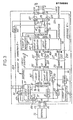
- This modified embodiment is illustrated in Figs. 3 and 4 in which we find all the elements already described, included in the isolation circuit 2 and the interfaces 3 and 4.
- a relay coil 472 is in parallel with the call ringtone 471 or replaces the call ringtone.
- a transformer 37 as well as a call contact 34 and an opening contact 321.
- a secondary winder 371 of the transformer 37 connects the terminal 31 of the power source 31 to the terminal B1 of the CTL contactor.
- a primary winding 370 of the transformer 37 and the contacts 34 and 321 are in series in a branch arranged in parallel with the sector input terminals S of the power source 31.
- the contact 321 is controlled by the relay coil 32 and is opened at the same time as the closing of the first contact 320 following the putting into operation of the terminal TL simulating the off-hook of a conventional telephone set.
- a movable part of the contact 34 is actuated by one end of a second movable rod with a major insulating part 22A passing through the insulation circuit 2.
- the rod 22A is analogous to the rod 22C and parallel to it as shown diagrammatically in the Fig. 4.
- Another metal end of the rod 22A constitutes an armature of the call relay 472 in the interface 4.
- a clocked call signal transmitted by the line TR activates the relay 472 which produces a back-and-forth translation of the rod 22A and of the mobile part of the contact 34 at the rate of interruptions of the call signal.
- contact 34 reproduces periodic signal interruptions call in the form of periodic interruptions of the alternating current from the sector S which are transmitted to the terminal TL through the transformer 37 to excite a ringing call included in the terminal TL.
- Putting the TL terminal into operation closes the current loop in interface 3, which excites the relay 32 and consequently closes contact 320 and opens contact 321.
- Opening contact 321 interrupts the inrush current in the interface 3 at the same time as the call circuit 47 is disconnected from the line TR by switching switches 42T and 42R established by the relay 33 activated by the closing of the contact 320. Dialing, speech or data can then be transmitted as described with reference to Figs. 1 and 2.
- the battery supplies an oscillator producing an alternating signal at the terminals of the branch comprising the contacts 34 and 321 and the primary winding 370.
- the current of the sector is replaced by the alternating signal produced by the oscillator and the call signal produced in interface 3 is no longer affected by possible faults in the sector.
- the invention according to the various embodiments described above makes it possible to equip, in a simple and inexpensive manner, each telephone subscriber's home with a protective box BO replacing the earth connection currently used, the cost of which is high.
- the isolation circuit of the protection device then comprises two pairs of transmission and reception channels, such as the pair of channels 23T - 22T - 24T and 24R - 22R - 23R.
- the telephone line can be composed of a coaxial cable or of two broadband coaxial cables assigned to the two directions of transmission.
- the terminal can include a videophone, a videophone, a television receiver or a video recorder for example.
Landscapes
- Physics & Mathematics (AREA)
- Electromagnetism (AREA)
- Engineering & Computer Science (AREA)
- Computer Networks & Wireless Communication (AREA)
- Signal Processing (AREA)
- Telephone Function (AREA)
- Telephonic Communication Services (AREA)
- Cable Transmission Systems, Equalization Of Radio And Reduction Of Echo (AREA)
- Optical Communication System (AREA)
Applications Claiming Priority (2)
| Application Number | Priority Date | Filing Date | Title |
|---|---|---|---|
| FR8403381 | 1984-03-05 | ||
| FR8403381A FR2560726B1 (fr) | 1984-03-05 | 1984-03-05 | Dispositif de protection contre des perturbations electriques entre un terminal et une ligne telephonique |
Publications (1)
| Publication Number | Publication Date |
|---|---|
| EP0156693A1 true EP0156693A1 (de) | 1985-10-02 |
Family
ID=9301701
Family Applications (1)
| Application Number | Title | Priority Date | Filing Date |
|---|---|---|---|
| EP85400359A Ceased EP0156693A1 (de) | 1984-03-05 | 1985-02-26 | Schutzeinrichtung gegen elektrische Störungen zwischen einem Terminal und einer Telefonleitung |
Country Status (5)
| Country | Link |
|---|---|
| US (1) | US4679115A (de) |
| EP (1) | EP0156693A1 (de) |
| JP (1) | JPH0683139B2 (de) |
| CA (1) | CA1231427A (de) |
| FR (1) | FR2560726B1 (de) |
Families Citing this family (7)
| Publication number | Priority date | Publication date | Assignee | Title |
|---|---|---|---|---|
| US4991051A (en) * | 1986-09-12 | 1991-02-05 | Northern Telecom Limited | Protection arrangements for communications lines |
| JPH0734550B2 (ja) * | 1987-02-02 | 1995-04-12 | 富士通株式会社 | 給電路切替回路 |
| US4954923A (en) * | 1988-08-19 | 1990-09-04 | Cooper Industries, Inc. | Intrinsic safety module interface |
| GB2248373B (en) * | 1990-07-10 | 1995-04-12 | Fujitsu Ltd | Power feed line switching circuit for submarine branching device and method of feeding power to submarine cable communication system |
| US5245654A (en) * | 1991-10-10 | 1993-09-14 | Cermetek Microelectronics, Inc. | Solid state isolation device using opto-isolators |
| US5666402A (en) * | 1994-04-05 | 1997-09-09 | Electro-Metrics, Inc. | Fiber optic telephone line extension system |
| DE19845123B4 (de) * | 1998-09-30 | 2006-04-13 | Infineon Technologies Ag | Vorrichtung zum galvanisch getrennten Verbinden einer Telefonleitung mit einer Signalverarbeitungseinrichtung am Teilnehmerende der Telefonleitung |
Citations (2)
| Publication number | Priority date | Publication date | Assignee | Title |
|---|---|---|---|---|
| DE2707190A1 (de) * | 1977-02-18 | 1978-08-24 | Siemens Ag | Anordnung zur kopplung von stromkreisen in schlagwetter- oder explosionsgeschuetzten anlagen, insbesondere von eigensicheren und nicht eigensicheren stromkreisen |
| EP0006144A1 (de) * | 1978-06-15 | 1980-01-09 | Siemens Aktiengesellschaft | Schaltungsanordnung zum Übertragen von Signalen zwischen einer Datenübertragungseinheit und einem Datenendgerät |
Family Cites Families (9)
| Publication number | Priority date | Publication date | Assignee | Title |
|---|---|---|---|---|
| NL262555A (de) * | 1960-03-18 | |||
| US3558830A (en) * | 1969-04-09 | 1971-01-26 | Communication Technology Inc | Overvoltage transmission line protector |
| US3648110A (en) * | 1970-08-20 | 1972-03-07 | Bell Telephone Labor Inc | Circuit protection apparatus utilizing optical transmission path |
| US4015115A (en) * | 1975-12-09 | 1977-03-29 | International Telephone And Telegraph Corporation | Picture phone |
| GB1492153A (en) * | 1976-05-25 | 1977-11-16 | Standard Telephones Cables Ltd | Repeaters |
| US4249266A (en) * | 1979-11-06 | 1981-02-03 | Perkins Research & Mfg. Co., Inc. | Fiber optics communication system |
| JPS57135536A (en) * | 1981-02-17 | 1982-08-21 | Shiyouden:Kk | Safety device |
| US4420841A (en) * | 1981-05-29 | 1983-12-13 | Westinghouse Electric Corp. | Optically coupled bidirectional transceiver |
| US4558183A (en) * | 1983-10-03 | 1985-12-10 | Cellutron Corporation | Opto-coupler interfacing circuit |
-
1984
- 1984-03-05 FR FR8403381A patent/FR2560726B1/fr not_active Expired
-
1985
- 1985-02-26 EP EP85400359A patent/EP0156693A1/de not_active Ceased
- 1985-02-27 CA CA000475311A patent/CA1231427A/en not_active Expired
- 1985-02-27 US US06/706,287 patent/US4679115A/en not_active Expired - Lifetime
- 1985-03-05 JP JP60042012A patent/JPH0683139B2/ja not_active Expired - Lifetime
Patent Citations (2)
| Publication number | Priority date | Publication date | Assignee | Title |
|---|---|---|---|---|
| DE2707190A1 (de) * | 1977-02-18 | 1978-08-24 | Siemens Ag | Anordnung zur kopplung von stromkreisen in schlagwetter- oder explosionsgeschuetzten anlagen, insbesondere von eigensicheren und nicht eigensicheren stromkreisen |
| EP0006144A1 (de) * | 1978-06-15 | 1980-01-09 | Siemens Aktiengesellschaft | Schaltungsanordnung zum Übertragen von Signalen zwischen einer Datenübertragungseinheit und einem Datenendgerät |
Also Published As
| Publication number | Publication date |
|---|---|
| FR2560726B1 (fr) | 1986-11-21 |
| FR2560726A1 (fr) | 1985-09-06 |
| JPS60213139A (ja) | 1985-10-25 |
| JPH0683139B2 (ja) | 1994-10-19 |
| US4679115A (en) | 1987-07-07 |
| CA1231427A (en) | 1988-01-12 |
Similar Documents
| Publication | Publication Date | Title |
|---|---|---|
| US9923639B2 (en) | Optical combiner energy harvesting | |
| EP0056545A1 (de) | Einrichtung zur Fernortung von Unterbrechungen und Kurzschlüssen in einer Zweidrahtleitung | |
| EP0148651B1 (de) | Sender/Empfänger mit geringem Energieverbrauch für eine Zweiwegverbindung | |
| EP0541409A1 (de) | Bidirektionales Übertragungssystem, insbesondere faseroptisches, mit einem einzelnen Träger für beide Übertragungsrichtungen | |
| US20090116845A1 (en) | Tetintelligent optical transceiver capable of optical-layer management | |
| US4817204A (en) | Optical communication apparatus and method for telephone supervisory and audio signals | |
| Diaz | Fiber-to-the-home technologies | |
| EP0213607B1 (de) | Einrichtung für Fernmeldung über optische Fasern | |
| EP0156693A1 (de) | Schutzeinrichtung gegen elektrische Störungen zwischen einem Terminal und einer Telefonleitung | |
| FR2638923A1 (fr) | Unite d'acces a un support de transmission d'un reseau local | |
| CA1044828A (fr) | Procede et dispositif de telesurveillance et telelocalisation de repeteurs-regenerateurs d'impulsions | |
| EP0403999B1 (de) | Analoge Verbindungsschaltung für eine Fernsprechnebenstellenanlage | |
| EP0616460B1 (de) | Öffentlicher Telefonapparat | |
| EP0072721B1 (de) | System zur Lokalisierung von Kreisen und Unterbrechungen in einer Zweidrahtleitung | |
| Lehpamer | Introduction to power utility communications | |
| EP0966800B1 (de) | Steuervorrichtung für trägerstromübertragung auf einem niedervoltnetz | |
| FR2590430A1 (fr) | Joncteur pour systeme telephonique | |
| FR2859856A1 (fr) | Systeme et disposiif d'alimentation a distance d'un equipement de traitement d'informations | |
| US7567550B2 (en) | Broadband communications | |
| EP2718688B1 (de) | Lichtemittierende vorrichtung und verfahren zum testen einer glasfaser. | |
| EP2614598A1 (de) | Verfahren für den teleschutz eines elektrischen leitungsträgernetzwerkes | |
| EP0724349B1 (de) | Verfahren und Gerät zur Fernübertragung eines paralellen Abhöranrufs auf einer Fernsprechleitung | |
| Mogensen | Wide-band optical fibre local distribution systems | |
| Chapman et al. | Use of reflected light for low data rate upstream signalling in a single mode passive optical network | |
| EP0578070A1 (de) | Fernmeldegerät sowie Faksimilegerät |
Legal Events
| Date | Code | Title | Description |
|---|---|---|---|
| PUAI | Public reference made under article 153(3) epc to a published international application that has entered the european phase |
Free format text: ORIGINAL CODE: 0009012 |
|
| AK | Designated contracting states |
Designated state(s): DE GB IT |
|
| 17P | Request for examination filed |
Effective date: 19860327 |
|
| 17Q | First examination report despatched |
Effective date: 19880201 |
|
| STAA | Information on the status of an ep patent application or granted ep patent |
Free format text: STATUS: THE APPLICATION HAS BEEN REFUSED |
|
| 18R | Application refused |
Effective date: 19900412 |
|
| APAF | Appeal reference modified |
Free format text: ORIGINAL CODE: EPIDOSCREFNE |